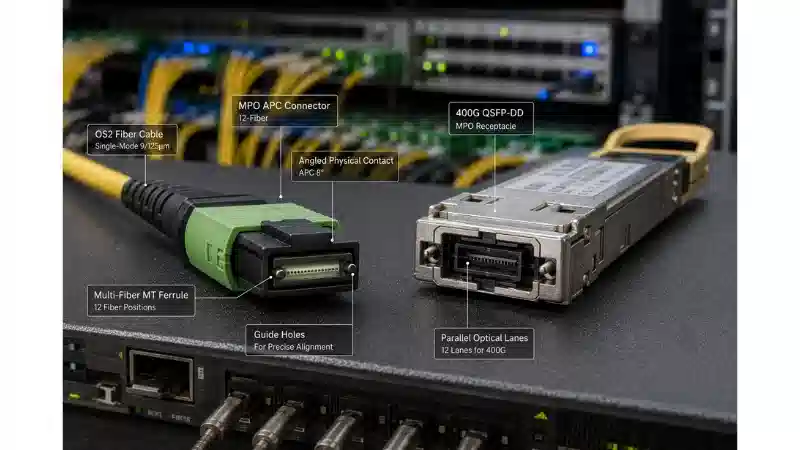
An MPO APC connector combines a multi-fiber MPO interface with an angled physical contact end face. The angled geometry redirects reflected energy away from the fiber core, helping the connection achieve lower reflectance and higher return loss than a comparable flat-polished interface.
MPO APC is common in parallel single-mode systems such as 400GBASE-DR4 and is also appearing in selected multimode PAM4 architectures. It is not a universal requirement for every 400G or 800G link. The transceiver interface must determine the connector polish, fiber mode, MPO format, pin configuration, polarity, and optical acceptance limits.
Readers who need a basic introduction can review what MPO and MTP mean and how MPO optical connectors work.

Quick Answer: When Is MPO APC Used?
Use an angled MPO interface when the exact transceiver or approved cabling architecture specifies it. Typical cases include:
- Parallel single-mode transceivers with an MPO-12 APC interface, including many 400G DR4 products.
- 800G parallel optics that specify MPO-16 APC or dual MPO-12 APC.
- Breakout assemblies built for a supported APC equipment port and defined lane map.
- Selected multimode PAM4 systems whose transceiver and structured-cabling design require multimode MPO APC.
- Links with a documented return-loss or reflectance requirement that cannot be met by the approved UPC architecture.
Do not select APC only from the network speed. High-speed optics also use MPO UPC, duplex LC, dual CS, SN, MMC, and other interfaces. Juniper's current 400G connector guide, for example, distinguishes MPO-12 APC parallel single-mode interfaces from MPO-12 BiDi UPC multimode interfaces.
What Angled Physical Contact Changes
MPO connectors use a rectangular MT-style ferrule to align several fibers in one interface. APC means that the physical-contact end face is polished at an angle, commonly approximately 8 degrees for the relevant MPO interface.
At any optical connection, a small portion of the light can reflect toward the transmitter. The angled surface changes the direction of that reflected energy so less of it returns through the fiber core. This is particularly important where the optical design is sensitive to reflected signals.
MTP is a registered connector platform from US Conec that conforms to the MPO interface while adding proprietary mechanical and performance features. The MTP connector platform can be supplied in different fiber counts, pin configurations, and polish geometries; the MTP name alone does not mean APC. FOCC also provides a broader explanation of MTP connector differences.
Return Loss and Reflectance
Return loss and reflectance describe the same reflected optical power from different mathematical directions:
- Reflectance is normally expressed as a negative value. A more negative value means less light is reflected toward the source.
- Return loss is expressed as a positive value. A higher value means better suppression of reflected power.
The correct wording is therefore lower reflectance and higher return loss. Fluke Networks provides a practical explanation in its return-loss testing guidance.
MPO APC vs MPO UPC
| Decision factor | MPO APC | MPO UPC |
|---|---|---|
| End-face geometry | Angled physical contact | Flat or near-flat ultra physical contact |
| Primary optical purpose | Lower reflectance and higher return loss | Low-loss physical contact for a supported flat-polished architecture |
| Traditional use | Parallel single-mode optics and reflection-sensitive systems | Established multimode parallel optics and other transceiver-specific systems |
| Emerging use | Selected multimode PAM4 and AI data-center links | Brownfield and new multimode systems that continue to specify UPC |
| Direct mating | Mate only with matching APC geometry | Mate only with matching UPC geometry |
| Identification | Part number, data sheet, interface drawing, ferrule geometry | Part number, data sheet, interface drawing, ferrule geometry |
APC and UPC should not be directly mated. The angled and flat ferrules do not create the intended physical contact, which can produce higher insertion loss, higher reflection, unstable results, and a risk of end-face damage.
Housing color can provide a clue but is not a sufficient specification. Confirm the product label and data sheet. FOCC's article on APC vs UPC connector polish explains the same optical principle in a single-fiber connector context.

APC Controls Reflection, Not Insertion Loss by Itself
The main purpose of an angled ferrule is reflection control. It does not automatically guarantee lower insertion loss than a UPC interface.
Insertion loss depends on several independent factors:
- Fiber-hole position and core alignment
- Guide-pin and guide-hole tolerances
- Fiber height and coplanarity
- Ferrule angle and surface geometry
- Fiber protrusion, withdrawal, and core dip
- Spring force and connector mechanics
- Polishing quality and end-face cleanliness
- Connector grade and random-mating performance
IEC 61300-3-30:2020 describes the measurement of rectangular multifiber ferrule geometry, including fiber position, ferrule angle relative to the guide-pin bores, fiber-tip radius, core dip, and coplanarity-related metrics.
A purchase specification should list insertion loss and return loss separately. Avoid copying one vendor's value as a universal MPO APC limit; use the exact transceiver, connector grade, system warranty, and project optical budget.
Standards and Documentation Map
| Document layer | What it controls | Relevant source |
|---|---|---|
| Transceiver data sheet | Speed, lane allocation, connector, fiber mode, reach, breakout, and optical budget | Cisco, Juniper, or the selected equipment vendor |
| One-row MPO interface | Standard interface dimensions for one-row MPO connectors and receptacles | IEC 61754-7-1:2014 |
| MPO-16 interface | Interface dimensions for two rows of 16 fibers | IEC 61754-7-3:2019 |
| MPO intermateability | Mechanical intermateability for standard MPO formats | TIA-604-5-F, FOCIS 5 |
| MPO-16 intermateability | Mechanical intermateability for MPO-16 | TIA-604-18-A, FOCIS 18 |
| End-face geometry | Ferrule angle, fiber height, protrusion or withdrawal, radius, core dip, and coplanarity | IEC 61300-3-30 |
| Visual inspection | Classification of debris, scratches, and defects | IEC 61300-3-35:2022 |
| MPO cable-plant testing | Attenuation, polarity, length, and optical return loss | IEC TR 61282-15:2017 |
| Installed MPO attenuation test | Attenuation, polarity, and length using MPO-interface test equipment | IEC 61280-4-5:2020 |
Standards define interfaces and test methods, but the transceiver data sheet still controls the equipment-facing connector. A connector can conform mechanically to MPO standards and still be wrong for the application because of polish, fiber mode, active positions, pins, or polarity.
Main MPO APC Applications

400G DR4 and 4×100G Breakout
400GBASE-DR4 carries four parallel single-mode transmit lanes and four receive lanes. Many products use an MPO-12 APC interface with eight active fibers and four unused center positions.
Cisco's 400G QSFP-DD transceiver data sheet describes the QDD-400G-DR4-S as a four-pair single-mode module with an MPO-12 interface and support for up to four 100GBASE-DR breakout links within the documented reach.
FOCC's guide to single-mode MTP breakout explains how parallel lanes can be separated into lower-speed interfaces. A supported breakout assembly must preserve the connector polish, active fiber map, polarity, remote connector type, and link-loss budget.
800G Parallel Optics
800G does not use one universal connector. Juniper's current 800G connector guide includes both MPO-16 APC and dual MPO-12 APC designs, alongside LC, CS, SN, MMC, and other formats.
MPO-12 and MPO-16 are not interchangeable. The ferrule layout, key position, adapter, active positions, and lane map can differ. FOCC's overview of MPO connector types for data centers provides additional context for choosing the physical format.
Selected Multimode PAM4 Applications
Multimode MPO traditionally used flat-polished interfaces, while APC was strongly associated with single-mode transmission. Selected vendors now offer multimode MPO APC solutions for PAM4-based AI and cloud architectures.
CommScope's discussion of angled multimode MPO connectivity explains why reflected signals receive more attention as multimode lane rates and modulation complexity increase. This does not mean every PAM4 or multimode link requires APC. Use the interface explicitly specified by the transceiver and cabling system.
Trunks, Harnesses, and Cassettes
The angled connector may be used in MPO/MTP trunk cabling, equipment patch cords, conversion assemblies, and high-density backbone links.
Breakout designs can use MPO/MTP harness cables to map one multi-fiber port to LC or another remote interface. The MPO side can be APC while the breakout side uses LC UPC or LC APC, provided the complete assembly matches the equipment and topology.
Structured systems can also place the MPO interface inside MPO/MTP cassette modules. Adapter orientation, cassette polarity, internal fanout mapping, and maximum module loss must be included in the channel design.
When MPO APC Is Not Required
- The transceiver specifies UPC. Installing an APC cable into a flat-polished equipment port is an incompatibility, not an upgrade.
- The architecture uses duplex LC or another connector. The speed label alone does not prove that an MPO port exists.
- A clean brownfield UPC plant remains supported. Existing infrastructure can be retained when the equipment vendor approves it and the plant passes inspection, loss, polarity, and application requirements.
- A hybrid migration assembly is approved. Some architectures can connect an APC equipment port to existing UPC structured cabling through a purpose-built, documented assembly.
- The connector type has not been confirmed. Do not order a generic "400G MPO cable" before the exact module and interface are identified.
Selection Checklist: Format, Pins, Key, and Polarity
Fiber Mode and MPO Format
Record the exact fiber type and format:
- OS2 for the specified single-mode application
- OM4 or OM5 only for a supported multimode APC application
- MPO-8, MPO-12, MPO-16, MPO-24, dual MPO-12, or another documented format
- Total fiber positions and active fiber positions
FOCC's MPO connector components page shows why ferrule, pin, housing, spring, boot, and key design must be considered as a complete mechanical system.
Pinned or Unpinned
A pinned connector has guide pins; an unpinned connector has guide holes. One pinned and one unpinned ferrule normally form the mating pair. Many equipment receptacles are pinned, but this must be verified for the exact transceiver rather than assumed.
FOCC's explanation of male and female MTP connectors covers pin terminology and its relationship to cable assemblies.
Key Orientation and Polarity
Key orientation controls the physical orientation of the ferrule. Polarity controls which transmit position reaches which receive position. A connector can have the correct key orientation and still have the wrong lane map.
The BOM should state Method A, B, C, or an application-specific mapping, along with key orientation, pin configuration, active fiber positions, and the transceiver lane assignment. FOCC's guide to MPO polarity methods should be used for the detailed mapping rules.
Adapter Compatibility
Adapters align the connector housings but do not correct a mismatch in polish, pins, fiber count, key position, or polarity. Review the mechanical format and channel loss before using an MPO adapter in a critical link.
Illustrative 400G DR4 BOM Template
The following is a procurement template, not a record of an installed FOCC customer project. Values shown as "verify" must come from the selected transceiver and project specification.
| BOM field | Illustrative requirement |
|---|---|
| Local transceiver | Cisco QDD-400G-DR4-S or another approved 400GBASE-DR4 module |
| Remote transceiver | Matching 400GBASE-DR4 module or supported 4×100GBASE-DR breakout |
| Equipment interface | MPO-12 APC |
| Fiber | OS2 parallel single-mode fiber |
| Active positions | Four transmit and four receive positions; verify the module map |
| Cable pin configuration | Verify against both transceiver receptacles |
| Key and polarity | Application-specific map approved by the equipment and cabling design |
| Maximum cable length | Within the module reach after allowing for all connectors and passive components |
| Maximum IL | Define per mated pair and for the complete assembly or channel |
| Minimum RL | Define per active fiber at the specified wavelength |
| Inspection | Full ferrule and all active positions inspected before mating |
| Factory report | Per-fiber IL, RL where required, polarity, serial number, date, and tester identification |
Where the remote interface is LC, a purpose-built MPO-to-LC breakout cable must map each optical lane to the correct remote transceiver.
Brownfield UPC Migration Decision
- Identify the new equipment interface. Confirm APC, UPC, or another connector from the exact transceiver data sheet.
- Identify the installed plant. Record fiber mode, MPO format, polish, pins, polarity, adapters, cassettes, and connector count.
- Inspect and clean every ferrule. Do not make a migration decision from historical test results alone.
- Measure the current channel. Verify attenuation, polarity, length, and return loss where the application requires it.
- Check vendor approval. Determine whether the new optic supports the existing UPC plant or an APC-to-UPC hybrid assembly.
- Compare the options. Retain UPC, add an approved hybrid component, replace only equipment-facing cords, or replace the structured plant.
- Document rollback. Keep the existing accepted path available until the new channel passes equipment and optical acceptance.
The migration should be driven by compatibility and measured performance rather than a blanket rule that all older UPC infrastructure must be removed.
Inspection, Cleaning, and Acceptance Testing
MPO ferrules expose several fiber end faces and a large mating surface. One particle can affect several lanes. Inspect the complete ferrule, guide pins or guide holes, and every active fiber position before mating.
Use cleaners and inspection tips designed for the exact pinned or unpinned MPO interface. FOCC's guide to cleaning fiber optic connectors provides the basic inspect-clean-reinspect process.

Acceptance Evidence
| Evidence | Required record |
|---|---|
| Inventory | Cable ID, part number, MPO format, polish, pins, fiber mode, length, and serial number |
| Visual inspection | Pass/fail for the full ferrule and each active fiber under the specified criteria |
| Polarity | Source position, destination position, lane assignment, and pass/fail |
| Insertion loss | Fiber position, direction, wavelength, reference method, measured value, limit, and margin |
| Return loss | Fiber position, wavelength, measured value, minimum limit, and pass/fail where required |
| Test control | Tester model, serial number, calibration status, operator, date, and electronic result file |
Do not infer return loss from insertion loss. A channel can pass the attenuation budget while still showing poor reflection performance.
Common Specification Mistakes
| Mistake | Why it fails | Better approach |
|---|---|---|
| Assuming every 400G or 800G link needs APC | High-speed optics use several connector architectures | Follow the exact transceiver data sheet |
| Mating APC to UPC | Angled and flat ferrules do not create the intended contact | Use matching polish geometry |
| Selecting by connector color | Color conventions vary across products | Confirm the part number and interface drawing |
| Assuming MTP means APC | MTP is an MPO-compatible connector platform, not a polish definition | Specify MPO or MTP and APC or UPC separately |
| Ordering only "MPO-12 cable" | Fiber mode, polish, pins, polarity, active positions, and loss remain unknown | Write a complete BOM |
| Treating APC as a lower-IL guarantee | APC primarily controls reflection | Specify IL and RL independently |
| Confusing key orientation with polarity | The ferrule can be oriented correctly but mapped incorrectly | Require an optical lane map |
| Treating MPO-12 and MPO-16 as interchangeable | Ferrule layout, key location, adapters, and lane allocation differ | Match the exact transceiver interface |
| Skipping ferrule inspection | Contamination can affect several fibers at once | Inspect, clean, and re-inspect before mating |
| Replacing every UPC brownfield link | Some approved systems can retain a measured UPC plant | Test the plant and evaluate approved migration options |
FAQ
Q: Is MPO APC always single mode?
A: No. APC has traditionally been common in single-mode MPO systems, but selected multimode PAM4 products now use angled MPO interfaces. The transceiver and cabling architecture must explicitly support multimode APC.
Q: Can MPO APC connect directly to MPO UPC?
A: No. The angled and flat end faces are not designed as a mating pair. Use matching polish geometry or an approved architecture that converts between the two interfaces without directly mating incompatible ferrules.
Q: Does MPO APC have lower insertion loss?
A: Not automatically. APC primarily improves reflection performance. Insertion loss depends on alignment, ferrule geometry, polishing, cleanliness, mechanics, and connector grade.
Q: Is MPO-12 APC used for 400G DR4?
A: It is a common interface for 400GBASE-DR4 parallel single-mode optics, but the cable must also match the module's pin configuration, active fiber positions, polarity, reach, and loss budget.
Q: Does 800G use MPO-12 or MPO-16 APC?
A: Both exist. Some 800G products use dual MPO-12 APC, while others use MPO-16 APC or a different connector. Verify the exact module before ordering.
Final Procurement Checklist
- Transceiver manufacturer, model, and platform support
- Connector geometry: APC, UPC, or another interface
- MPO format and total fiber positions
- Active transmit and receive positions
- Single-mode or multimode fiber
- Pinned or unpinned cable connectors
- Key orientation and polarity map
- Maximum insertion loss and minimum return loss
- Test wavelength and reference method
- Trunk, harness, breakout, patch cord, or cassette construction
- Adapter and random-mating requirements
- Inspection and cleaning criteria
- Per-fiber IL, RL, and polarity report
- Serial traceability and electronic test records
The correct MPO APC connector is not selected by speed, color, or fiber count alone. Start with the exact transceiver interface, then match the polish, fiber mode, ferrule format, pins, polarity, optical limits, and acceptance evidence.