A fiber optic connector pull test does not establish a useful load rating unless the report identifies the assembly, the point where force was applied, the loading direction, the test conditions and the acceptance results. A pulling-cap test, a straight pull on a mated connector and a side pull on a mated connector place stress on different parts of the assembly. Passing one does not qualify the others. Before accepting a connector for an FTTH or outside-plant installation, check that its proof-test evidence matches the actual cable, termination and mounting arrangement, and that the applicable optical and mechanical requirements were met.

What Does a Connector Pull-Test Result Actually Prove?
A connector proof test establishes how a defined device under test (DUT) performs under a specified static load. It is not a universal strength rating for every cable diameter, connector variant or mounting arrangement sold under the same product name.
For a terminated optical cable, the DUT may include the plug, cable jacket, strength members, termination hardware and, depending on the test configuration, a pulling cap or mating adaptor. All of these details matter. A change in cable construction or termination method can change the load path even when the outward appearance of the connector stays the same.
The central question is not simply whether the assembly survived a force measured in newtons. It is whether the specified load was applied to the intended assembly and whether the connector remained coupled where applicable, avoided physical damage and met the required optical performance criteria. Those are the fundamental outcomes addressed by the IEC 61300-2-50:2026 connector proof-test standard.
A report can support qualification of the tested configuration. Extending that result to another design requires a documented engineering justification, a relevant qualification family or additional testing. A revised jacket, crimp, strength-member arrangement or adaptor does not automatically invalidate every earlier report, but neither should it be assumed equivalent without review.
What Changed in IEC 61300-2-50:2026?
Published on 29 September 2026, IEC 61300-2-50:2026 replaces the 2007 edition. The most consequential addition for pre-terminated field cables is a defined straight-pull configuration involving the pulling cap, plug and cable. The revision also updates test procedures for hardened connectors, aligns test severity with the component and performance category, and adds details that must be specified and reported.
These changes make the precise configuration and reporting basis particularly important when comparing an older result with a new purchasing specification. They do not establish that every connector must be tested at a single force, speed or duration. The appropriate values depend on the applicable procedure and performance requirements; they should be checked against the relevant standard text and project specification, not inferred from a supplier's marketing summary.
Nor does the standard's published stability date act as an expiry date for existing test reports. An earlier report may remain useful supporting evidence if its scope, conditions and acceptance limits are relevant to the current project. Where the contract calls for the 2026 edition, the supplier should identify differences between the earlier test and the specified procedure and explain whether additional evidence is necessary.
Three different tests are often mentioned in the same conversation. IEC 61300-2-50 addresses connector proof testing under static load. IEC 61300-2-6:2023 addresses tensile strength of the coupling mechanism under axial loading in normal service. IEC 61300-2-42 concerns static side loading of a cord's strain relief. Their purposes overlap in mechanical reliability, but a report for one method should not be presented as proof that a different test has been completed.
Three Static-Load Configurations and Their Differences
The procedure named on the test report needs to correspond to the way the product will be loaded. IEC 61300-2-50:2026 includes three configurations that buyers should distinguish.
| Configuration | Tested arrangement | Load direction | What the result addresses | What it does not replace |
|---|---|---|---|---|
| Pulling-cap straight pull | Pulling cap, plug and cable | Axial | The specified capped assembly under an installation-type pull | Proof of the mated coupling interface under load |
| Adaptor straight pull | Adaptor, plug and cable | Axial | The assembled and mated connection under direct tension | Pulling-cap or lateral-load qualification |
| Adaptor side pull | Adaptor, plug and cable | Lateral | The mated connection under a specified side-load arrangement | Axial-load and other environmental tests |
Straight Pull on the Pulling Cap, Plug and Cable
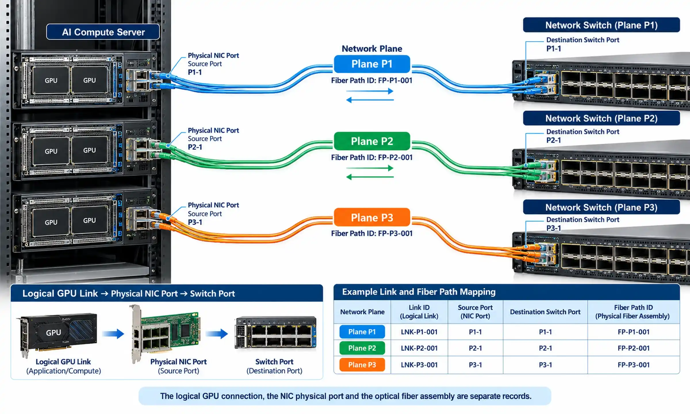
A pre-terminated cable may be pulled through a duct, riser or other route with the connector protected by a pulling cap or eye. The test must represent the actual cap-to-plug-to-cable arrangement, including how the pulling load is transferred to the cable's load-bearing elements.
The report should identify the cap, its attachment method, the cable construction and the specified load. A result for one pulling-eye design cannot automatically be carried over to another cap or cable. FOCC's pre-terminated cable with a pulling eye illustrates why installation hardware belongs in the assembly description rather than being treated as an incidental accessory.
What it proves: the identified capped assembly completed the specified axial-load procedure and met its stated acceptance criteria.
What it does not prove: that the plug and adaptor will meet an independently specified axial or side-load requirement when mated. Optical and physical assessment still matters within the applicable proof-test procedure; a pulling-cap result is not solely a test of whether the cap remains attached.
Straight Pull on the Adaptor, Plug and Cable
This arrangement applies axial load to a connector that is mated with an adaptor or receptacle. The load path passes through the termination and the engaged connector assembly. Depending on the construction, the relevant points of concern may include the coupling feature, housing, cable retention and changes in optical performance.
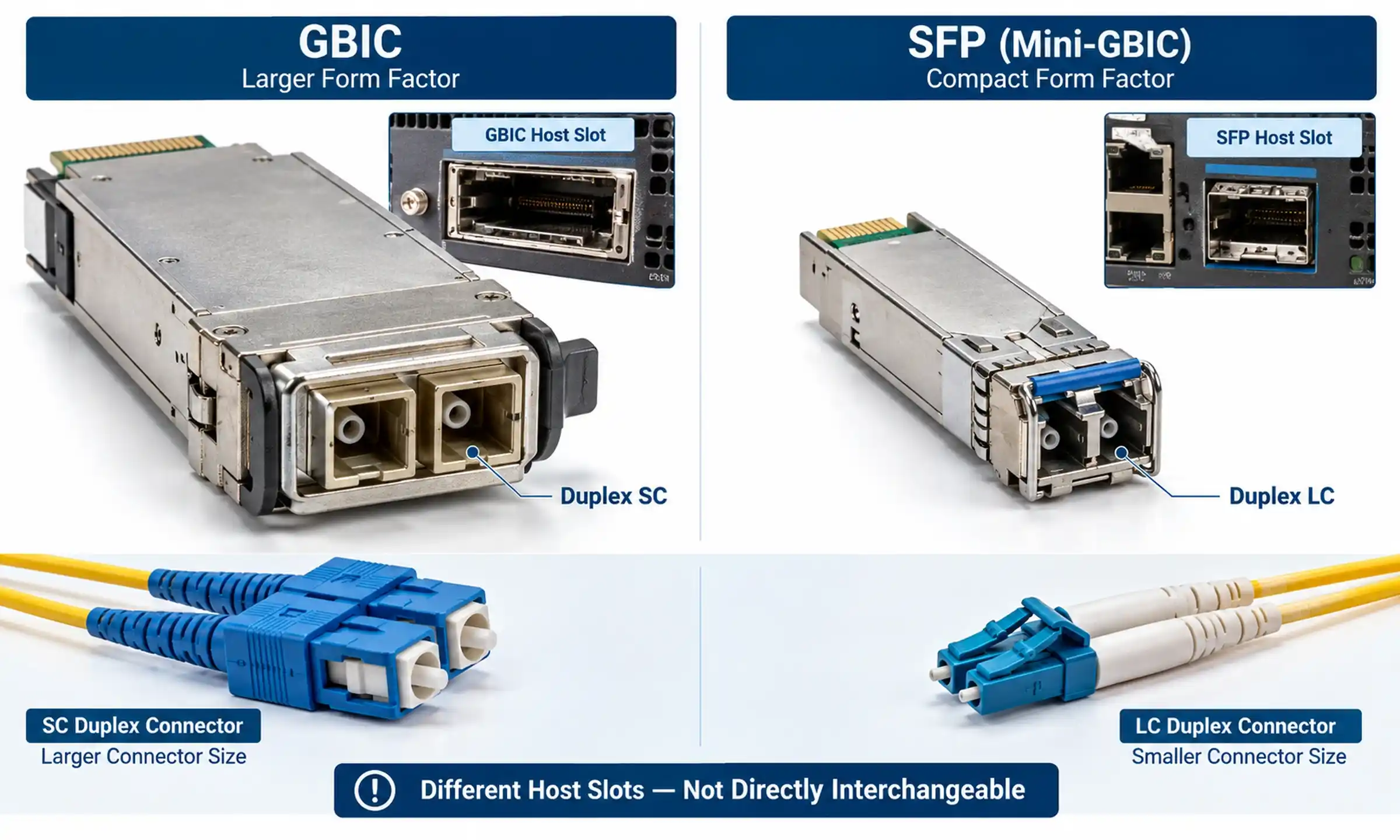
The distinction matters for FullAXS-to-LC cable assemblies, where the outdoor-end connection and the LC end have different housings and mating arrangements. A single result cannot be assumed to cover both terminations or every possible receptacle.
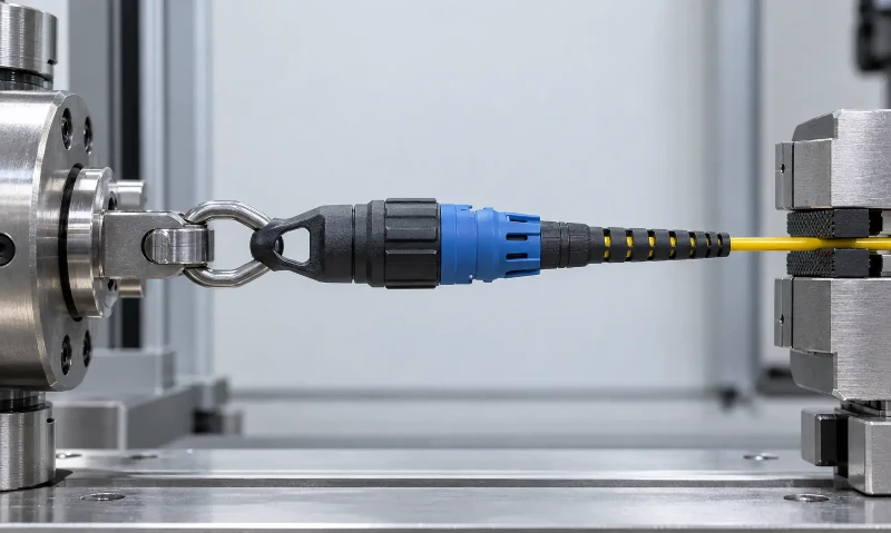
What it proves: the specified mated assembly met the stated axial proof-test conditions. The record should show the mating component and fixture, not just the cable part number.
What it does not prove: that the same assembly will pass a side pull, or that the coupling mechanism has separately met every requirement of IEC 61300-2-6. Check the method and its scope before treating the reports as interchangeable.
Side Pull on the Adaptor, Plug and Cable
A side pull introduces lateral loading at a mated connector. This may be relevant where the cable leaves a receptacle at an angle or where installation geometry could place sideways force on the connection. The fixture, cable exit geometry and prescribed direction are therefore essential parts of the report.
An SC ODVA outdoor adaptor, for example, is mounted through a panel or enclosure. Its mounting arrangement differs from that of a free-hanging adaptor. The product page establishes the connector format and installation context, not any unverified proof-test result.
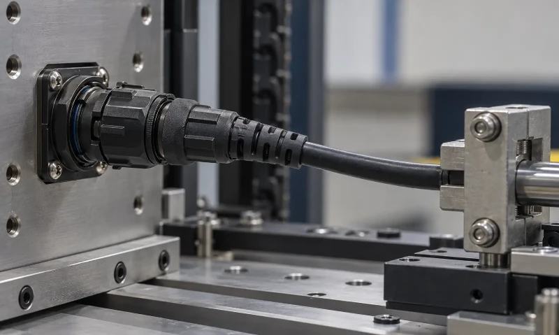
What it proves: the identified mated assembly met the specified side-load procedure and acceptance conditions.
What it does not prove: pulling-cap strength, axial proof-test strength, long-term vibration resistance or environmental durability. The separate IEC 61300-2-42:2014 strain-relief side-load test may also be relevant to a project, but its result should be identified by its own method and conditions.
Why Connector Proof Load Is Not Cable Tensile Strength
Cable tensile ratings and connector proof-test loads are frequently placed side by side on specification sheets. They are not necessarily comparable.
A cable rating describes the cable construction under a defined tensile condition, often distinguishing permissible installation and service loads. A connector proof test concerns an assembled termination and, in some configurations, the mating interface or pulling hardware. The loads can travel through different structural elements and fixtures. A high cable rating cannot establish the load that a terminated connector will withstand.
The boot is one example of why component details matter. Different fiber optic connector boot designs accommodate different connector bodies and cable sizes; the presence of a boot alone does not demonstrate a particular side-load rating. Likewise, strength-member retention must be evaluated for the actual cable and termination design rather than assumed from the bulk-cable specification.
When comparing supplier documents, keep the units consistent, but do not stop at a conversion between pounds-force and newtons. Record what carried the load, whether the connection was mated, the duration and the acceptance requirements. Converting units does not make dissimilar procedures equivalent.
Can Pull-Test Results From Different Suppliers Be Compared?
Only within clearly defined limits. Consider three figures that could appear on a purchasing comparison sheet: 450 N for a capped axial pull, 112 N for a mated axial pull and 67 N for a mated side pull. These values are illustrative of different report entries; they are not universal IEC limits, FOCC test results or measurements of a particular product.
| Illustrative report entry | Declared force | Test configuration | Can it be ranked against the others? |
|---|---|---|---|
| Entry A | 450 N | Pulling-cap straight pull | No. The capped assembly carries the specified axial load. |
| Entry B | 112 N | Adaptor straight pull | No. This evaluates a different load path through a mated connection. |
| Entry C | 67 N | Adaptor side pull | No. Direction and fixture differ from both axial procedures. |
A buyer who sorts that table from highest to lowest force would draw the wrong conclusion. Entry A cannot demonstrate that its connector coupling is stronger than the one in Entry B, nor does Entry C automatically describe an inferior product. The results answer different questions.
A meaningful supplier comparison begins by matching the DUT, standard edition, configuration, direction, specified force, test duration, severity and optical and physical acceptance limits. When those conditions differ, state the difference instead of declaring a winner.
Even when two reports use the same nominal force, the results may not establish equivalence if one covers a different cable outside diameter, adaptor, boot or termination design. If the project involves a specific load and mating geometry, request evidence for that arrangement rather than selecting the largest number on a datasheet.
What Should a Complete Connector Proof-Test Record Show?
A statement such as "pull test passed" does not identify what was tested or what the acceptance decision means. A usable fiber optic connector test report connects a traceable sample to a defined procedure, measured observations and specified acceptance criteria.
IEC 61300-2-50:2026 includes preparation, initial optical measurements, mounting, the applicable load procedure, and final measurements and examination in its published structure. The test record should make the relevant steps auditable. The exact measurement timing, monitoring arrangements and numerical limits must follow the applicable procedure and project requirements; continuous insertion-loss and return-loss monitoring should not be presented as a universal obligation without checking those requirements.
| Report field | Evidence to check | Why it matters | If missing |
|---|---|---|---|
| Device under test | Connector, adaptor, cable and assembly identification | Establishes which physical configuration the result covers | Request matching identification |
| Sample traceability | Sample identifiers, revision or lot information where applicable | Connects results to the claimed product | Request traceability |
| Standard and edition | Method number and publication year | Identifies the procedure against which evidence was produced | Clarify the standard basis |
| Test arrangement | Pulling-cap or adaptor configuration and fixture description | Identifies the load path and connection state | Request setup details |
| Load conditions | Force, direction, application and hold conditions | Determines whether the result matches the specified duty | Cannot establish equivalence yet |
| Severity or performance category | Applicable category and agreed test level | Prevents comparison across unlike requirements | Request the applicable basis |
| Optical acceptance | Required optical properties, test conditions and limits | Defines what acceptable optical performance means | Request criteria and results |
| Measured observations | Initial, required in-test and final readings as applicable | Shows whether unacceptable degradation occurred | Request the relevant data |
| Mechanical examination | Evidence concerning uncoupling, cracking or other specified damage | Checks physical integrity after loading | Request examination findings |
| Test conclusion | Pass/fail decision against stated criteria | Connects results to a defined requirement | Do not treat status as confirmed |
Missing evidence and failed performance are different findings. An incomplete report may justify withholding qualification pending clarification; it does not, by itself, prove the product failed the mechanical test. Conversely, a complete report showing an out-of-limit result cannot be approved merely because the assembly remained physically intact.
General optical link certification is not a substitute for a connector proof test. An optical loss test set may be part of a measurement arrangement, and an OTDR can be useful for diagnosing a link, but neither a Tier 1 nor a Tier 2 field certificate alone establishes compliance with the specified component-level static-load procedure.
When Is Additional Connector Testing Necessary?
Additional evidence should be considered whenever a qualification report does not cover the proposed configuration or the project's acceptance requirements. The decision depends on what changed and whether the supplier can justify equivalence from controlled design information and existing test records.
- A different cable or termination: a change in outside diameter, strength-member construction, crimp or attachment method may alter how the load reaches the connector.
- A different mating arrangement: changing the adaptor, receptacle or mounting method can change the axial and lateral load paths.
- A different installation method: adding a pulling cap or introducing a cable exit angle may require evidence for a configuration not included in the earlier report.
- A different specified standard: an older edition or a GR-3120-based qualification record may contain useful evidence, but it is not automatically a test report to IEC 61300-2-50:2026.
For example, an outdoor SC FastConnect field-assembly connector is not necessarily represented by the test data for a different factory-terminated outdoor connector. The specific termination method and cable combination determine what evidence should be requested.
Static-load proof testing also does not establish resistance to every service condition. Where repeated mating is relevant, IEC 61300-2-2:2026 on mating durability addresses a different failure mechanism. Its severity levels depend on the component and performance category; no single mating-cycle count should be applied to all connectors. Vibration, sealing and temperature exposure likewise require evidence appropriate to those risks.
Confirming Test Evidence for a Specific Connector Assembly
The most efficient technical enquiry identifies the assembly before requesting a force rating. In the case of a FullAXS-compatible outdoor connector, for instance, the purchaser should identify the intended mating interface and cable termination rather than relying on the outdoor housing name alone.
To discuss a fiber optic connector proof-test requirement with FOCC Fiber, provide:
- The connector model, interface and intended mating adaptor or receptacle.
- The cable type, outside diameter, jacket and relevant strength-member construction.
- The factory-terminated or field-assembled configuration.
- The pulling-cap or pulling-eye arrangement, if installation pulling is required.
- The expected axial or side-load condition and the required test method.
- The required IEC edition, severity or contractual performance category.
- The optical acceptance limits and any required measurement conditions.
- The requested quantity and whether samples or test records are needed before approval.
FOCC Fiber can use these details to confirm the relevant product configuration and discuss which specification sheets, samples or test documents are available for review. A product listing or an IP-rated housing is not proof that a specific assembly has passed IEC 61300-2-50:2026. For project-specific documentation and quotation requirements, contact the FOCC Fiber team with the intended configuration and acceptance criteria.
Frequently Asked Questions
Does a higher pull-force rating mean a stronger fiber optic connector?
Not without comparable test conditions. A pulling-cap axial result and a mated side-load result assess different arrangements. Compare force values only after confirming the DUT, direction, fixture, duration and acceptance criteria.
Can an older test report or a GR-3120 report support a 2026 IEC qualification?
It can provide relevant technical evidence, but it does not automatically demonstrate that IEC 61300-2-50:2026 was performed. Check the procedures and acceptance requirements specified by the project. Where equivalence cannot be established, request supplementary evidence or testing.
Does changing the cable diameter always require a completely new proof test?
Not automatically. A different cable diameter can alter retention and strain relief, so the change must be assessed. Qualification-family evidence or engineering justification may be sufficient in some projects; others require additional testing of the revised assembly.