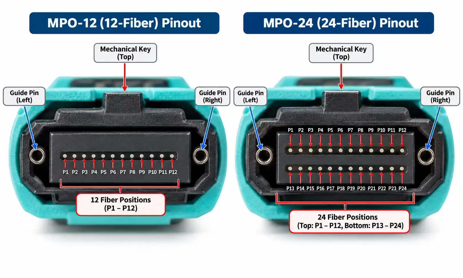
To turn an AI fabric port map into a cable bill of materials (BOM), start with the two physical endpoints of each link, the network plane and the actual transceiver part numbers. Confirm the optical interface at both ends, then assign the fiber path, connector arrangement, polarity, assembly length and testing requirements. Only after those checks can the port schedule be converted into a cable order.
An 800G port does not automatically require one MPO-16 cable. Depending on the selected optics, it may use one MPO-16, two MPO-12 interfaces or duplex LC connections. Breakout support also depends on the switch, module and far-end interfaces. This guide follows a small, illustrative AI-network cabling schedule from its logical links to individual factory cable IDs, then shows what still needs approval before production.
Why Multi-Plane AI Networks Need a Physical Port Map
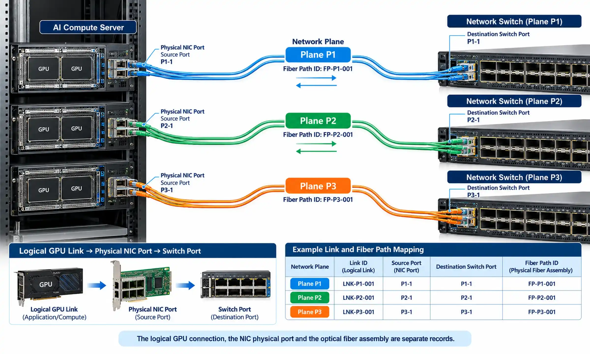
A multi-plane fabric uses separate network paths to distribute traffic and limit the effect of a failure within one plane. The cabling schedule must preserve those boundaries: a cable with the correct optical connectors can still be installed between the wrong source and destination ports.
In its October 2026 Flattened Planar Fabric announcement, Meta describes eight independent 100G links from each GPU to eight different switches, one per plane. That does not mean eight physical cables per server, nor does it identify the MPO connectors used in a particular deployment. A GPU, its associated NIC interfaces and the physical switch ports are separate items to record. Similarly, Meta's 128 × 800G IceCube switching capacity does not establish a cable count or guarantee that each port supports 8 × 100G breakout.
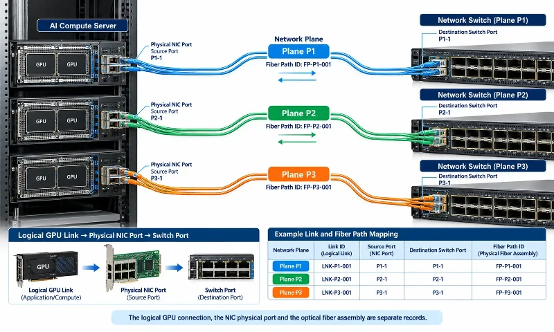
For the cabling team, a usable network diagram is the one that identifies the actual port where a cable is plugged in. The mapping database should therefore distinguish the logical GPU or fabric endpoint, the NIC or switch interface that presents the signal, and the physical fiber assembly that carries it.
Build the Port-to-Port Mapping Table First
Assign every planned connection a Link ID and a Fiber Path ID. A Link ID represents an optical or Ethernet service path; a Fiber Path ID identifies the installed route. They may be one-to-one for a native link, but a breakout parent port can serve two or more separately identified links. Do not use a GPU number as a substitute for a physical NIC port.
The following schedule is an illustrative engineering example, not a record of Meta's deployment. Device and port names are placeholders. It includes native 800G connections using two different DR8 connector options and one proposed 800G-to-2 × 400G breakout. The breakout rows are intentionally held for far-end compatibility approval.
| Plane | Link ID | Source physical port | Destination physical port | Optical configuration | Fiber Path ID | Assembly ID(s) |
|---|---|---|---|---|---|---|
| P1 | LNK-P1-001 | Leaf-01 / Eth1/1 | Spine-01 / Eth1/1 | 800G DR8, single MPO-16 APC interface at each end | FP-P1-001 | CAB-P1-001 |
| P2 | LNK-P2-001 | Leaf-02 / Eth1/2 | Spine-02 / Eth1/2 | 800G DR8, two MPO-12 APC interfaces at each end | FP-P2-001 | CAB-P2-001A; CAB-P2-001B |
| P3 | LNK-P3-001A | Leaf-03 / Eth1/3, breakout child A | Compute-03 / NIC1-Port1 | 400G DR4 child of an 800G DR8 dual-MPO port; far-end PMD pending | FP-P3-001A | CAB-P3-001A |
| P3 | LNK-P3-001B | Leaf-03 / Eth1/3, breakout child B | Compute-04 / NIC1-Port1 | 400G DR4 child of the same parent port; far-end PMD pending | FP-P3-001B | CAB-P3-001B |
For P3, Eth1/3 is one physical 800G parent port. The A and B suffixes are illustrative labels for two logical 400G channels, not two additional physical 800G ports or official switch CLI syntax. The two 400G destinations must be associated with separate breakout child interfaces in the approved switch configuration. Both ends need supported Ethernet rates, compatible PMDs and an appropriate FEC configuration.
The port schedule should also contain fields for rack position, optical part number at each end, installed fiber type, patching location and installation status. In a large project, keep the logical mapping and cable inventory in separate worksheets joined by the Link ID and Assembly ID rather than repeating long notes in every row.
Match Each Link to the Actual 800G Optical PMD
PMD comes before connector selection. The optical physical-medium specification determines how many transmit and receive fibers are needed and whether the link uses parallel fibers or wavelength multiplexing. The module's exact product ID then identifies its physical connector, end-face polish and host requirements. Modules with the same nominal 800G rate may have different front-panel interfaces.
The Cisco OSFP 800G transceiver data sheet provides a useful model-specific example:
| Example module | Optical interface | Module connector | Fiber medium | Planning consequence |
|---|---|---|---|---|
| OSFP-800G-DR8P | 800GBASE-DR8 | Single MPO-16 APC | Parallel single-mode | One 16-active-fiber path |
| OSFP-800G-DR8 | 800GBASE-DR8 | Dual MPO-12 APC | Parallel single-mode | Two MPO-12 interfaces, eight active fibers per interface |
| OSFP-800G-VR8P | 800GBASE-VR8 | Single MPO-16 APC | Parallel multimode | Use the specified multimode fiber and distance limit |
| OSFP-800G-VR8 | 800GBASE-VR8 | Dual MPO-12 APC | Parallel multimode | Two parallel-fiber connector groups |
| OSFP-2X400G-FR4 | 2 × 400GBASE-FR4 | Dual duplex LC UPC | Single-mode | Two duplex paths; an MPO-16 connection is not required at the optical ports |
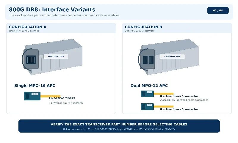
The table identifies Cisco product examples; it is not a universal connector list for every 800G SR8, VR8, DR8 or FR4 module. Do not assume that all single-mode modules have the same connector or that an 800G socket always supports a requested breakout. The host platform, supported module, port mode and destination module must be checked together.
For the illustrative P1 and P2 native links, both ends are assumed to use matching supported DR8 variants. The proposed P3 breakout uses an 800G DR8 dual-MPO interface at the parent port; compatible 400GBASE-DR4 modules and host breakout support must be selected and confirmed before ordering. A passive MPO cable cannot create breakout capability where the network equipment does not provide it.
Choose Direct Links, Trunks and Breakouts From the Fiber Path
After the optical ports are known, trace each cable route through the racks, trays and any distribution areas. A direct patch assembly can suit a short, accessible run. Longer or frequently reconfigured routes may benefit from structured MPO/MTP trunk cabling and designated patch locations. The decision depends on maintenance access, pathway capacity and the approved link-loss budget; neither arrangement is mandatory for every 800G link.
Keep the terms separate:
- Native parallel link: one 800G optical service carried by the required set of fibers. It may occupy one MPO-16 connection or two MPO-12 connections, depending on the module.
- Breakout link: one supported parent port provides separate lower-rate child interfaces. Each child needs its own destination, link record and defined fiber mapping.
- Trunk assembly: a pre-terminated multi-fiber cable joining distribution points or equipment. The number of fibers in the trunk is not necessarily equal to the number of active lanes in one transceiver.
- Harness or fanout: an assembly that distributes fibers to multiple connectors. An MPO/MTP harness must be specified for the actual endpoint interfaces; it is not automatically interchangeable with a dual-MPO DR8 layout.
If a route passes through MPO cassette modules or cross-connects, count each mated connection and confirm the complete end-to-end lane map. Do not choose a cassette merely to convert an inconvenient connector without checking the optical PMD, fiber mapping and additional loss.
Length is the measured cable pathway with approved service loops and routing allowances, not simply the straight-line distance between cabinets. Before releasing the order, verify cable outside diameter, pulling-eye dimensions if specified, tray capacity, minimum bend radius, jacket fire rating and installation method. General MPO trunk types and length considerations are useful background, but the production length still comes from the project route survey.
Short fixed connections may use a compatible AOC or DAC instead of separately supplied optics and passive trunk cabling. That choice should be made before generating the passive cable BOM because an active assembly has different replaceability, power and service-access implications. AOC reach and power figures are product-specific; they cannot be borrowed from another supplier's specification.
Convert the Port Map Into a Factory Cable BOM
A production BOM must tell the manufacturer what to make and which link each assembly belongs to. At minimum, record the assembly ID, parent Link ID, fiber count and medium, connector A/B, pinning, polish, approved lane map, length, quantity, labels and required reports. Add cable construction, jacket rating, pulling-eye or packaging requirements where relevant.
The next table carries the exact IDs from the port map above. Its lengths are illustrative planning assumptions, not field measurements. The lane-map references are project documents that must be populated and signed off with fiber-position-to-fiber-position and Tx-to-Rx information; they are not invented polarity standards.
| Assembly ID | Linked service | Assembly and active fibers | Connector A / B | Lane map | Planned length | Qty | Release status |
|---|---|---|---|---|---|---|---|
| CAB-P1-001 | LNK-P1-001 | Direct OS2 parallel assembly; 16 active fibers | Non-pinned MPO-16 APC / non-pinned MPO-16 APC | LM-P1-001 | 12 m | 1 | Pending signed lane map and route survey |
| CAB-P2-001A | LNK-P2-001, connector group A | Direct OS2 assembly; 8 active fibers in MPO-12 positions | Non-pinned MPO-12 APC / non-pinned MPO-12 APC | LM-P2-001A | 22 m | 1 | Pending signed lane map and route survey |
| CAB-P2-001B | LNK-P2-001, connector group B | Direct OS2 assembly; 8 active fibers in MPO-12 positions | Non-pinned MPO-12 APC / non-pinned MPO-12 APC | LM-P2-001B | 22 m | 1 | Pending signed lane map and route survey |
| CAB-P3-001A | LNK-P3-001A | Proposed OS2 400G DR4 child link; 8 active fibers | MPO-12 APC / MPO-12 APC, pinning to confirm at both ports | LM-P3-001A | 14 m | 1 | Hold: far-end module, breakout mode and mating approval |
| CAB-P3-001B | LNK-P3-001B | Proposed OS2 400G DR4 child link; 8 active fibers | MPO-12 APC / MPO-12 APC, pinning to confirm at both ports | LM-P3-001B | 14 m | 1 | Hold: far-end module, breakout mode and mating approval |
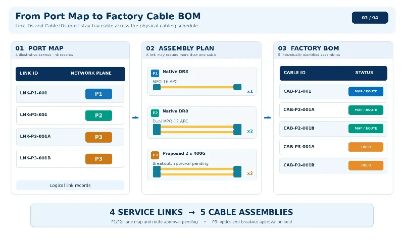
These four service links produce five separately listed cable assemblies: one for the single-MPO P1 link, two for the dual-MPO P2 link and one for each P3 breakout child. The quantities shown belong to this four-link example only. They cannot be multiplied into a full AI cluster procurement quantity without the complete port inventory and spare policy.
For P1 and P2, the connector choices reflect the Cisco module interfaces used in this example. However, the appropriate end-to-end polarity and the cable route still need engineering approval. For P3, leaving pinning and compatible far-end part numbers unresolved is deliberate: the item cannot be released for manufacturing just because its connector shape appears plausible.
Each production line should also carry the two endpoint labels or a reference to a controlled label schedule. Labels should identify the assembly and destination unambiguously, including the A/B connector group on a dual-MPO connection. Do not substitute one shared label for two physically different assemblies.
Check Polarity, Mating Interfaces and the Loss Budget
Polarity and connector pinning
For each assembly, confirm the complete path from the transmit lanes of one optic to the corresponding receive lanes of the other. The correct result depends on the actual optic pinout, adapter key orientation, any cassettes and the cable's fiber-position mapping. There is no safe universal rule that every 800G DR8 trunk must use Type-C. An approved deployment may use a different mapping, including Type-B in some point-to-point MPO-16 designs.
Document the final fiber-position mapping in the lane-map record before manufacturing. The MPO polarity methods describe the underlying arrangements, but the order must specify the arrangement that produces the required end-to-end Tx-to-Rx result.
Pinning must be checked separately from polarity. In the Cisco OSFP examples above, the MPO optical ports are pinned and require non-pinned cable plugs. Mating through panels can change the required connector combination; review the actual connection sequence rather than treating all trunk ends as male or all module-side ends as female. The distinction between pinned and non-pinned MTP/MPO connectors matters at every mating interface. APC and UPC endfaces must not be mated as if they were interchangeable.
Loss-budget calculation
Calculate the estimated passive-path loss for the complete channel:
Estimated channel loss (dB) = fiber attenuation + all mated connection losses + any other passive component losses.
The permitted result depends on the selected optical specification and the applicable device data sheet. Cisco, for example, lists a maximum supported insertion loss of 3 dB for its named OSFP-800G-DR8 and DR8P modules. That is not a universal 800G limit, a guaranteed field result or a substitute for the manufacturer's assembly specification.
Define separate acceptance values for each component and the installed channel. Factory loss measurements of an individual trunk cannot account for uninstalled patch panels or other site connections. Conversely, an end-to-end channel reading does not identify which individual MPO fiber or mating interface is responsible for a problem.
Factory Inspection and Site Acceptance
The cable BOM should identify the report required with each assembly ID. A practical factory acceptance record includes the selected test wavelength, reference method, instrument identification, connector inspection result, per-fiber continuity and polarity, insertion-loss readings, acceptance limit and pass/fail decision. Return-loss measurements and interferometry reports should be included where required by the approved product specification or purchase order, rather than presented as universal obligations for every assembly.
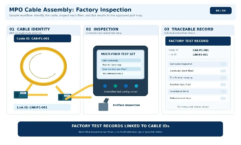
For high-density connectors, inspect every applicable endface before mating and clean when necessary, then inspect again. Fluke Networks' 800G testing guidance explains the importance of measuring multi-fiber insertion loss and automatically verifying polarity for parallel-optics links. A single average value across an MPO connector is not a substitute for the individual active-fiber results required by the project.
Site acceptance should use the same Link ID and Assembly ID as the mapping and factory records. Verify:
- Installed route: source rack, destination rack, tray route, patch panel position and physical labels agree with the approved map.
- Connector condition: relevant endfaces are inspected and, if needed, cleaned with the correct tools before connection.
- Continuity and polarity: each active fiber reaches its intended destination; both groups of a dual-MPO interface are accounted for.
- Channel loss: measured loss is checked against the approved end-to-end budget using a documented reference method.
- Host and service state: selected optics are recognized, required breakout child ports appear, and link operation, error counters and application-level connectivity are verified by the network team.
A link-up indication by itself does not prove that the cable is attached to the correct network plane or that the service meets its performance requirements. Keep the test record, as-built port map and final BOM together so a later replacement can be ordered without reconstructing the physical route.
Pre-Order Checklist for 800G MPO Cable Assemblies
| Verification item | Question before purchase | Required evidence |
|---|---|---|
| Physical endpoints | Do the source and destination rack, equipment and actual port identifiers match? | Approved port-to-port mapping revision |
| Optical compatibility | Are both optic part numbers and host port modes compatible, including any breakout children? | Platform/module support information and approved PMD pairing |
| Fiber and connectors | Are fiber medium, active-fiber count, connector type, polish and pinning correct at both ends? | Signed component specification and mating diagram |
| Lane mapping | Does each Tx fiber arrive at its intended Rx lane through the full channel? | Approved fiber-position/lane-map drawing |
| Mechanical route | Are length, bend radius, cable diameter, pulling hardware and fire-rating requirements confirmed? | Route survey and installation specification |
| Optical budget | Does the estimated total channel loss meet the selected PMD's project-approved allowance? | Link-budget worksheet and assembly limits |
| Testing | Which per-fiber measurements, inspection records and report formats are required? | Factory acceptance plan and site test procedure |
| Traceability | Can every physical assembly be matched to a link, label and test report? | Assembly IDs and controlled BOM revision |
Before submitting an RFQ, send the manufacturer the approved mapping table, BOM, optical module information and any lane-map drawings. Identify items that are fully specified separately from those still awaiting transceiver or route approval. For custom MPO/MTP fanout assemblies or trunks, also confirm branch lengths, breakout geometry, labeling positions, packaging and acceptance records when applicable.
The result should be a cable schedule that technicians can install, inspectors can test and a manufacturer can quote without guessing at port assignments or fiber orientation. A clear mapping record will not replace optical qualification, but it makes every required check traceable to a specific assembly before production begins.