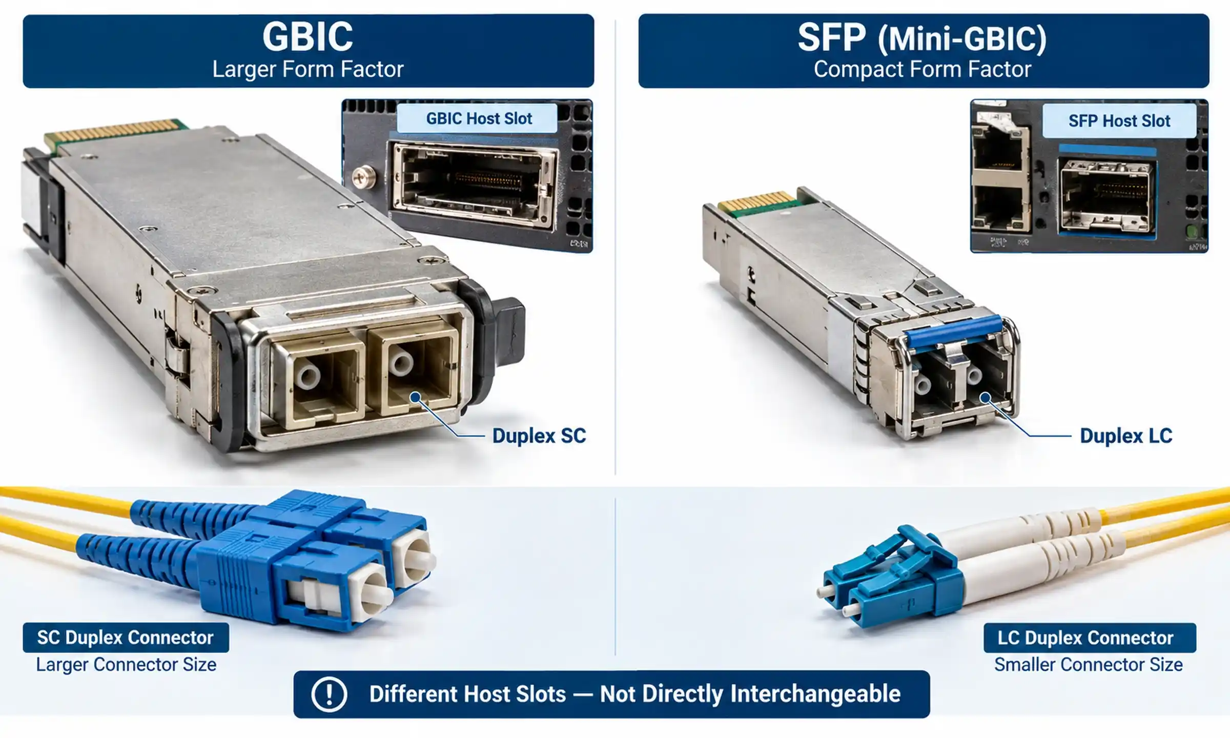
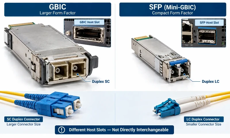
GBIC and SFP modules cannot be exchanged in the same host slot, but they can communicate across a fiber link when their optical interfaces and operating conditions are compatible. A switch with GBIC slots cannot accept an SFP directly. However, a 1000BASE-LX/LH GBIC at one end of a link may work with a compatible 1000BASE-LX/LH SFP at the other. Replacing a GBIC-based switch also does not necessarily require replacing the installed fiber cable.
The practical questions are whether both devices support the selected optics, whether the optical link can meet the new receiver's requirements, and whether the existing patching can be adapted without introducing faults. This guide covers those decisions and the checks needed before a legacy link is cut over.
GBIC vs SFP: What Actually Changes?
GBIC stands for Gigabit Interface Converter. SFP stands for Small Form-factor Pluggable and is also commonly called Mini-GBIC. Both are removable transceiver form factors, but their host connectors and physical sizes are different. The term Mini-GBIC refers to SFP; it is not a third interchangeable slot type.
| Consideration | GBIC | SFP |
|---|---|---|
| Physical form factor | Larger legacy module | Smaller, higher-density module |
| Host interface | GBIC slot | SFP slot |
| Hot-swappable | On equipment designed to support it | On equipment designed to support it |
| Typical optical connector on 1G fiber models | Duplex SC | Duplex LC |
| Common Gigabit Ethernet optics | 1000BASE-SX, LX/LH and vendor-specific extended-reach variants | 1000BASE-SX, LX/LH and vendor-specific extended-reach variants |
| Direct module-to-slot replacement | Cannot be inserted into an SFP slot | Cannot be inserted into a GBIC slot |
| Interoperability over fiber | Possible when the two optical interfaces and host configurations are compatible | |
A smaller module does not by itself increase line rate. Replacing a 1 Gb/s GBIC connection with a 1 Gb/s SFP connection retains a 1 Gb/s link. A move to 10 Gb/s is a separate project involving suitable switch ports, optics and cabling.
Can GBIC and SFP Work Together?
1. Installing one module in the other's slot
No. A passive sleeve or a different fiber connector cannot turn a GBIC slot into an SFP slot. The modules use different host-side mechanical and electrical interfaces. If the existing chassis has only GBIC slots, the normal migration path is to replace or upgrade the switch or line card with equipment that supports SFPs. Do not assume that an unsupported third-party converter will be recognized or supported by the host.
2. Connecting a GBIC switch to an SFP switch
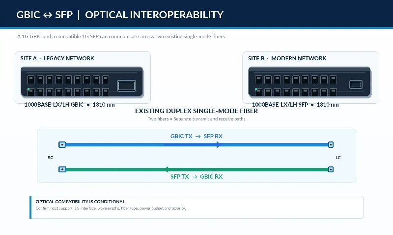
Yes, conditionally. The optical fiber carries a compatible physical-layer signal; it does not carry information about the size of the module housing. For example, a pair of supported 1000BASE-SX optics can form a link over suitable multimode fiber even if one is packaged as a GBIC and the other as an SFP.
The same principle applies to compatible LX/LH implementations, but the actual transmitter power, receiver sensitivity, wavelengths, fiber characteristics and link conditions must still be checked. A matching name on the label is a starting point, not a substitute for reading the two data sheets. A typical 1000BASE-SX multimode SFP, for instance, is intended for an 850 nm multimode link; it is not a direct optical match for a 1310 nm LX transmitter.
3. Replacing a GBIC switch while retaining installed fiber
Often possible. The permanent cable plant can remain in place if it is the correct fiber type, passes inspection and testing, and meets the new link's optical requirements. The equipment-side patch cords may change from SC to LC. The switch configuration and module support must also be verified before the old hardware is removed.
GBIC-to-SFP Optical Compatibility Checklist
Before ordering modules, record the current GBIC's exact part number and the far-end interface. Then compare the proposed SFP against the actual link, rather than against the GBIC's form factor alone.
| Check | What to confirm | If it does not match |
|---|---|---|
| Host support | Switch model, line card, port type, firmware and transceiver support list | The module may not be recognized or the port may remain disabled. |
| Ethernet interface | Compatible 1000BASE physical-layer implementation at both ends | The two sides may not establish a valid optical link. |
| Operating rate | Both ports can operate at the required 1 Gb/s rate | A fixed-rate port cannot be made compatible merely by changing the patch cord. |
| Wavelengths | Each receiver supports the wavelength emitted by the opposite transmitter | An SX/LX mismatch or incorrect BiDi pair may leave the receiver without usable light. |
| Fiber plant | SMF or MMF, installed grade, measured length and relevant bandwidth limitations | Reach may be unsupported or errors may occur. |
| Connectors and polarity | SC/LC termination, suitable end-face polish and transmit-to-receive routing | There may be no receive signal or excessive insertion loss. |
| Optical power | Minimum launch power, receiver sensitivity, maximum input power and path loss | Insufficient power or receiver overload may prevent reliable service. |
| Legacy MMF conditions | Whether the specified LX/LH implementation requires mode-conditioning cords | Modal dispersion can affect the link even when received power seems acceptable. |
| Port settings | Applicable negotiation mode, enabled state and service configuration | Physical or higher-layer connectivity may fail. |
| Diagnostics | Whether each module and switch supports optical diagnostic reporting | Missing DOM data may limit monitoring, but does not necessarily prevent operation. |
For a Cisco platform, the Optics Compatibility Matrix is one way to check transceiver and software support. Other vendors have their own compatibility lists. Neither a matching plug nor a matching wavelength guarantees that the host will accept a module.
One detail is frequently missed during switch replacements: 1000BASE-X operates at a nominal 1 Gb/s link rate, but that does not mean its optical interfaces have no negotiation function. Depending on the platform, IEEE 802.3 Clause 37 negotiation may exchange link capabilities and remote-fault information. Check both devices' settings rather than automatically disabling negotiation. Cisco describes these platform-dependent conditions in its 1000BASE-X auto-negotiation guidance.
Matching Legacy GBIC Models to SFP Optics
Legacy Cisco part numbers offer a useful example of how a migration can retain an optical interface while changing the host-side form factor. The following are optical-interface comparisons, not plug-compatible replacements or guarantees of platform support.
| Legacy Cisco GBIC | Comparable Cisco SFP family | Optical interface | Primary fiber consideration |
|---|---|---|---|
| WS-G5484 | GLC-SX-MM | 1000BASE-SX, approximately 850 nm | Multimode fiber; permitted reach depends on grade |
| WS-G5486 | GLC-LH-SM | 1000BASE-LX/LH, approximately 1310 nm | Single-mode fiber; legacy MMF needs additional checks |
| WS-G5487 | GLC-ZX-SM | Vendor-specific 1000BASE-ZX, approximately 1550 nm | Single-mode fiber; pay particular attention to power limits |
The source model families are documented in Cisco's GBIC installation note and Gigabit Ethernet SFP data sheet. The ZX designation describes a long-reach vendor implementation; it should not be presented as though every 1000BASE-ZX product has one universal IEEE-defined reach or power specification.
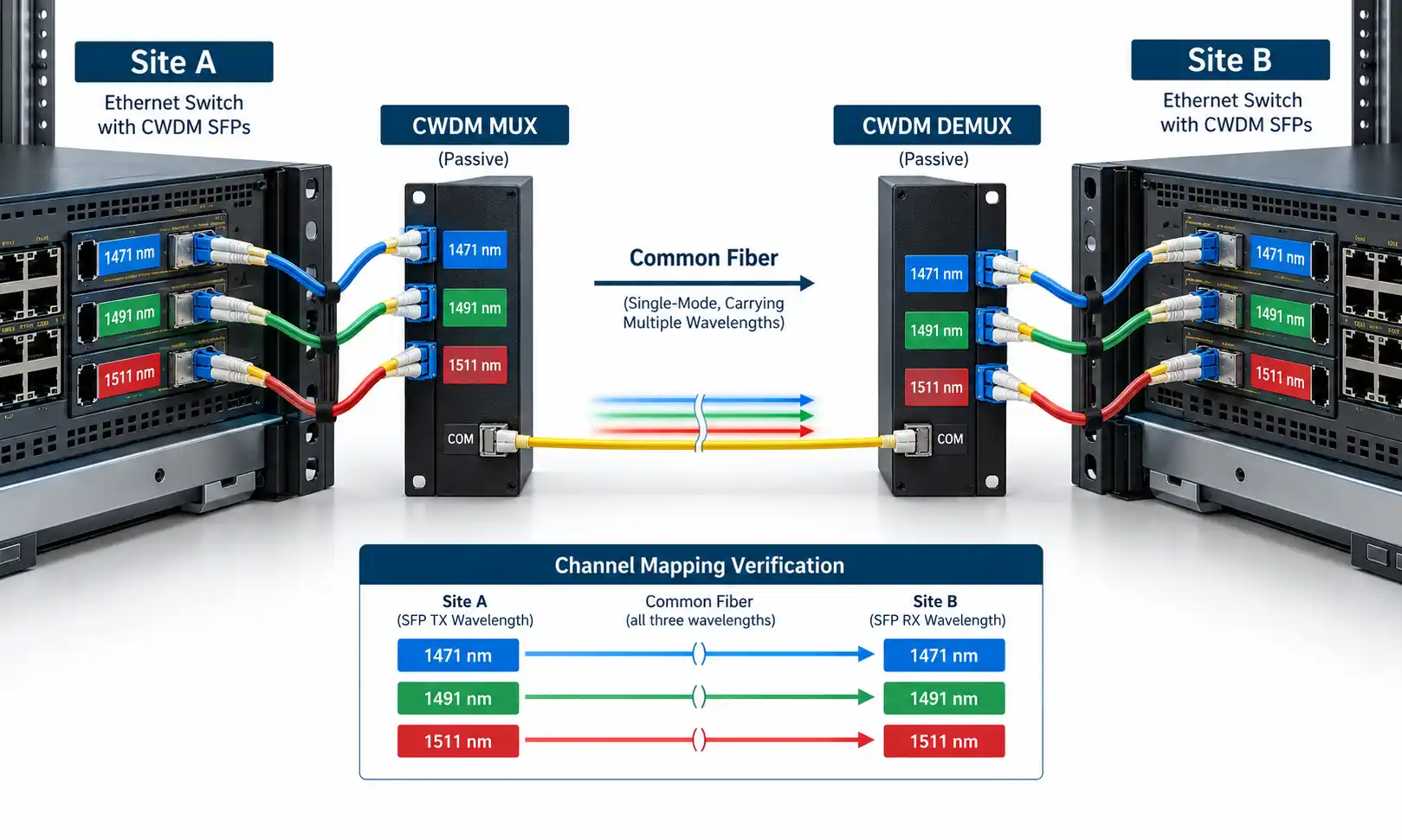
If the replacement switch has SFP slots and the existing link uses LX/LH over single-mode fiber, a compatible 1000BASE-LX/LH 1310 nm SFP may be an appropriate candidate. Verify the new switch's module support and compare both ends' optical specifications before ordering. Do not substitute a BX/BiDi module without matching its complementary transmit and receive wavelengths; those single-fiber optics use a different arrangement from ordinary duplex SX or LX connections.
Can Existing SC Fiber Cabling Be Reused?
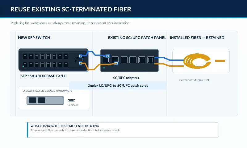
In many installations the permanent optical cable ends at an SC patch panel, while the legacy GBIC switch connects to that panel through SC patch cords. Replacing the switch with an LC-equipped SFP device does not require changing the building fiber if the plant itself remains suitable.
For a single-mode link with SC/UPC patch-panel ports, an LC/UPC-to-SC/UPC duplex single-mode patch cord can connect the SFP to the existing panel. Choose its length and fiber construction for the rack layout, and preserve the correct transmit/receive polarity. A connector change does not alter the fiber's transmission properties or convert an incompatible optical standard into a compatible one.
Before reusing a cable plant, confirm what is actually installed. Check labeling against available test records, inspect the connector end faces, and measure the fiber where its condition is uncertain. Do not assume that every yellow cable is single-mode or that an old orange cable has a particular multimode performance grade.
Legacy 1000BASE-LX/LH over OM1 or OM2
Some older Gigabit Ethernet deployments use LX/LH optics on 62.5/125 µm or 50/125 µm multimode cable. The concentrated laser launch can interact with the multimode fiber's modal characteristics and produce differential mode delay. For specified legacy MMF links, mode-conditioning patch cords provide an offset-launch arrangement that reduces this problem.
Do not treat mode conditioning as a universal requirement for every single-mode optic or every multimode grade. Cisco's mode-conditioning patch-cord installation note specifies a pair of cords for its defined 1000BASE-LX/LH use on FDDI-grade, OM1 and OM2 MMF, and warns against applying those cords to OM3 and newer fiber in that configuration. Check the exact optic and fiber before deciding which patch cords to order.
Check both ends of the optical power range
More received light is not always better. The projected worst-case receive power must remain above the receiver's sensitivity limit, while the highest plausible receive power must remain below its maximum input specification. For extended-reach optics such as ZX, a short test span may have too little loss. A correctly selected single-mode optical attenuator may be necessary where the module documentation calls for one. The required value must come from the actual transmitter, receiver and link specifications, not from a fixed rule applied to all GBIC-to-SFP upgrades.
How to Migrate from GBIC to SFP Step by Step
The sequence below applies to a planned equipment replacement where at least one endpoint is being upgraded. A mixed GBIC-to-SFP link still requires the same optical checks, even if only one switch changes.
Step 1: Record the working link before touching it
For each affected port, record the switch and line-card models, GBIC part number, far-end optic, physical port, fiber route, patch-panel positions and connector types. Save the current port and service configuration. Note link state, error counters and any available optical diagnostics. Some old GBICs cannot report digital optical power, so use available historical measurements or a suitable calibrated test method rather than inventing a baseline.
Step 2: Confirm the replacement switch and optics
Check that the new platform supports the chosen SFP in the intended port and software release. Match the required Gigabit Ethernet optical interface to the far-end module. Make sure that supported wavelengths, fiber types, transmit power and receiver limits are compatible. If only one end is upgraded, the unchanged GBIC remains part of the acceptance calculation.
Step 3: Inspect the fiber route and select patch cords
Confirm the permanent fiber type and its test history. Identify which patch cords need SC, LC or another approved termination. Check duplex polarity and connector polish. If the installation uses LX/LH on legacy multimode fiber, determine whether the specified mode-conditioning arrangement is required at both ends.
Step 4: Calculate the link budget and prepare rollback
Estimate the worst-case path attenuation using the actual fiber length, wavelength-dependent attenuation, connectors, splices and other components. Compare it with the new receiver's minimum-power requirement; separately confirm the short-link overload condition. Before the maintenance window, save the old configuration, label the existing patching and define the point at which the team will restore the original service if verification fails.
Step 5: Stage the new hardware
Install the proposed SFPs in the replacement switch in a controlled environment, using the manufacturer's handling instructions. Confirm that each module is recognized, that the port supports the required operating mode and that the intended configuration has been loaded. If a module is rejected, resolve the platform compatibility issue before the cutover. Do not rely on undocumented vendor-lock bypass commands as a migration plan.
Step 6: Inspect, clean and reconnect during the change window
Inspect connector end faces and clean them with suitable tools and methods before mating. A long-unused SC patch panel can contain contamination even when the old link still appears healthy. Follow an established fiber connector cleaning procedure and the equipment manufacturer's laser-safety precautions. Never look into a fiber or transceiver port to check whether it is transmitting.
Move the identified circuit to the new switch using the planned patch cords, retaining the documented polarity. Change one service group at a time where the topology allows it. Keep the original circuit labeling available until both physical and service checks have passed.
Step 7: Verify the optical and Ethernet link
Check module recognition, port status, transceiver alarms and available received-power readings. Confirm that the port's negotiation behavior matches the peer device's supported configuration. Then check the interface counters for errors and flaps. Where diagnostics are not available or are insufficient, use a suitable external measurement method under an approved maintenance procedure.
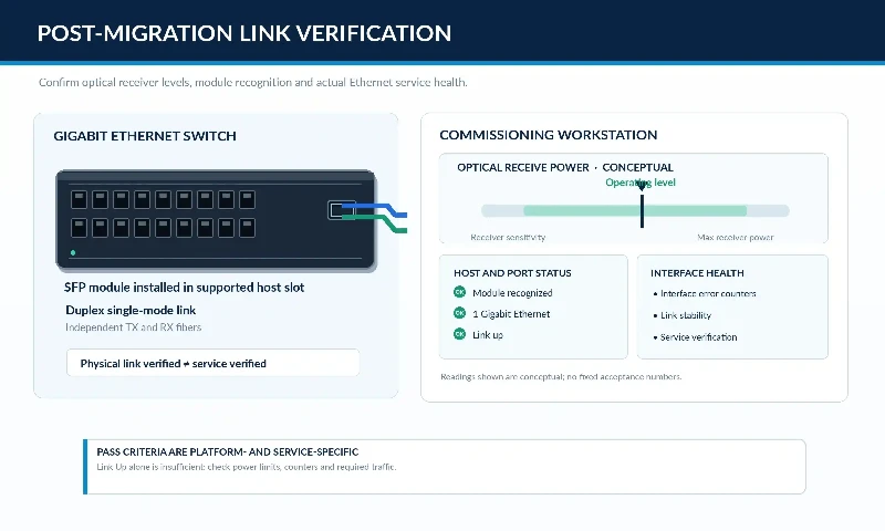
Step 8: Test the service, document results and close the change
Verify the required service rather than stopping at a green link light. Depending on the network, this may include expected VLAN reachability, MAC learning, routing neighbors, link aggregation behavior and application connectivity. Compare post-cutover errors and performance with the recorded baseline. If an acceptance criterion is not met, use the rollback procedure established before the change; then verify that the original service has been restored.
Illustrative Migration: A 1000BASE-LX/LH Building Link
Consider two buildings connected by an existing duplex single-mode fiber route. The old switch at Building A uses a supported 1000BASE-LX/LH GBIC with an SC patch connection. Building B retains a compatible 1000BASE-LX/LH optical interface. The replacement switch for Building A accepts supported 1G SFP modules.
In this example, the cable plant may remain unchanged. The engineer selects an SFP supported by the new switch, compares its optical specifications with the unchanged far-end module, and replaces the switch-side patch cord with one that presents LC at the SFP and the appropriate connector at the patch panel. The actual fiber span and optical power range must still be checked. After cutover, the engineer verifies receive power where available, the 1G link state, error counters and affected services.
This is a planning example, not a field test report. If the installed link were OM1 or OM2 multimode rather than single-mode, the same patch-cord choice could not be assumed; the LX/LH mode-conditioning requirements would need to be reviewed first.
Common GBIC-to-SFP Migration Failures
| Symptom | Likely checks | Next action |
|---|---|---|
| SFP is not recognized | Host support list, module part number, firmware and port type | Use a documented supported optic and configuration. |
| No light or no link after replacement | Far-end optic, SX/LX wavelength, duplex polarity and damaged or disconnected patching | Trace the actual Tx-to-Rx path and confirm optical compatibility. |
| Optical power is present but the link stays down | 1000BASE-X negotiation settings, interface state, optics and alarms | Compare both endpoints' configuration and documented capabilities. |
| High errors on a legacy MMF run | Fiber grade, LX/LH launch condition, distance and connection quality | Check the specified mode-conditioning requirements and test results. |
| Receiver reports excessive power | Long-reach optic, short fiber span and receiver input limit | Check whether the documented design requires attenuation. |
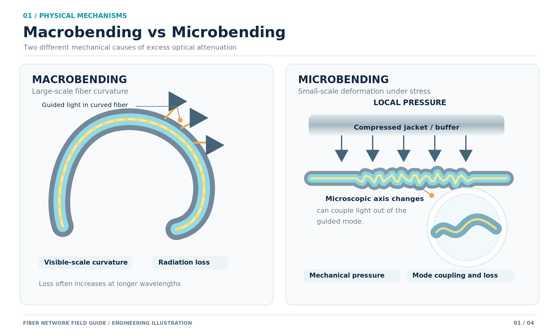
| Intermittent service after changing patch cords | Connector end faces, strain, bend radius and patch-panel routing | Inspect and correct the optical connections, then retest. |
| Link up but services unavailable | VLANs, trunks, routing, aggregation and security settings | Compare the new configuration with the recorded service baseline. |
If the module and port pass the basic checks but the fault remains, a controlled transceiver and switch-port loopback test can help isolate certain faults when the platform and test method support it. A loopback result does not replace end-to-end optical and service verification.
When Is Keeping the Existing GBIC Hardware Reasonable?
Not every functioning GBIC link needs an immediate replacement. Retaining it can be reasonable when the device remains supported for the application, spare parts are available, the link meets its service requirements and the operational risk of changing the equipment outweighs the expected benefit. Those conditions should be reviewed against the organization's lifecycle and security policies.
Migration becomes more compelling when the chassis or line card is unsupported, spare GBICs are difficult to source, port density is inadequate, maintenance risk is increasing, or a wider switch replacement is already planned. The business case should consider the new switch and module costs, any necessary patching, the maintenance window and the risk of downtime-not just the price of an SFP.
Frequently Asked Questions
Can I replace a GBIC with an SFP in the same switch?
No, not directly. GBIC and SFP use different host interfaces and slots. A GBIC-only switch needs a supported SFP-capable replacement platform or line card before SFP modules can be installed.
Can a GBIC and an SFP communicate over the same fiber?
Yes, if both ends support compatible optical interfaces and operating conditions. Confirm rate, transmit and receive wavelengths, fiber type, link attenuation, receiver power limits and host configuration. Matching module housings are not required.
Is Mini-GBIC the same as SFP?
Yes. Mini-GBIC is a commonly used name for the smaller SFP form factor. It is not a separate optical standard and does not imply compatibility with a legacy full-size GBIC slot.
Can I keep an SC patch panel when upgrading to an LC SFP?
Often. A correctly specified SC-to-LC patch cord can connect an existing SC patch panel to an LC-equipped SFP while leaving the permanent fiber in place. The cable must still match the fiber type, connector polish and optical requirements of the link.
Will replacing a GBIC with an SFP increase network speed?
No. A 1G GBIC-to-1G SFP migration remains a 1G link. Higher rates require switches and optics that support the target Ethernet interface, plus a cable plant that meets its transmission requirements.
Why does the new SFP show link down even though it fits the switch?
Physical fit does not establish end-to-end compatibility. Check host support, the far-end GBIC's actual interface, wavelength, fiber type, polarity, optical power and negotiation settings. If the physical link comes up but the service fails, review the switch configuration before replacing more optics.
For a GBIC-to-SFP upgrade, the key decision is whether the existing optical circuit can meet the replacement equipment's requirements. Establish that first, preserve the cable plant where it is suitable, and treat migration as a controlled equipment change with measurable acceptance criteria and a prepared rollback path.