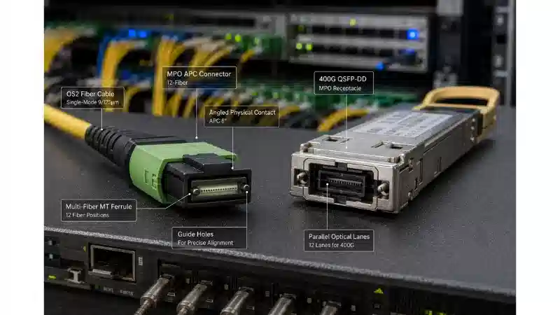
In the fast-paced world of fiber optic communications, high-density connectivity is critical for modern data infrastructure. With skyrocketing bandwidth needs driven by cloud computing, 5G networks, and artificial intelligence, efficient and scalable cabling solutions are essential. MPO/MTP connectors have emerged as key enablers, allowing multiple optical fibers to be connected in a single, compact interface. This revolutionizes data transmission in space-constrained environments like data centers. This article provides an in-depth exploration of MPO/MTP technology, covering its design, applications, and best practices, drawing on decades of industry expertise. Whether you're a network engineer or an IT manager, understanding MPO/MTP is vital for building future-ready networks.
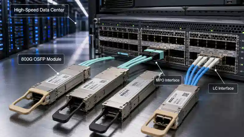
Imagine a data center where MPO/MTP cables weave through server racks, enabling seamless high-speed connections.
Understanding the Basics: What is MPO/MTP?
MPO/MTP refers to multi-fiber push-on connectors designed for high-density fiber optic applications. MPO, or Multi-fiber Push-On, is a standardized connector developed in the 1990s to meet the demand for parallel optics in telecommunications. These connectors house multiple fibers-typically 8, 12, 24, or up to 72-in a single rectangular ferrule, enabling quick, tool-free connections. The push-on mechanism, secured by a latch, ensures precise alignment without the need for screw threads or bayonet mounts used in older designs.
MTP is an enhanced version of MPO, featuring proprietary improvements like floating ferrules for better optical performance and removable housing for easier field repairs. While all MTP connectors meet MPO standards, not all MPO connectors offer MTP's advanced features. In essence, MPO/MTP spans a spectrum: MPO as the universal standard and MTP as the optimized variant for high-performance settings.
Why is MPO/MTP critical? Unlike single-fiber connectors like LC or SC, which lead to cable clutter when scaling to high speeds, MPO/MTP consolidates connections, reducing installation time by up to 75% and improving airflow in racks. This efficiency is crucial in data centers where space and power are limited.
Here's a diagram illustrating the MPO/MTP connector's components, including the ferrule, pins, and key orientation.
The ferrule is precision-engineered to maintain tight tolerances, ensuring low insertion loss (typically <0.35 dB for MTP) and high return loss (>60 dB). Fibers are arranged in a linear array, with guide pins in male connectors ensuring accurate alignment. Female connectors have corresponding holes. The key-up/key-down orientation prevents mismating, while polarity management aligns transmit (TX) and receive (RX) signals.

Anatomy of an MPO/MTP connector, showing male/female variants, pins, and adapter alignment.
Historical Evolution and Standardization of MPO/MTP
MPO/MTP originated in the late 1980s to support high-capacity telecom systems. The first MPO prototype, introduced in 1993, supported 12 fibers, addressing limitations of duplex connectors in parallel optics. By the 2000s, as high-speed Ethernet emerged, MPO/MTP adoption grew in enterprise networks. Enhanced MTP connectors, launched around 2005, introduced features like elliptical pin tips for smoother mating and better cleanability.
Standardization ensured reliability. Global standards defined MPO dimensions and performance metrics, supporting multimode and single-mode fibers for high-speed transceivers. Today, MPO/MTP underpins advanced modules, enabling data rates from 40G to emerging 800G configurations in AI-driven networks.
Technical Specifications: Inside MPO/MTP Design
MPO/MTP connectors are built for durability, with specifications tailored to fiber count, mode, and performance grade. Common configurations include 12-fiber for 40G/100G and 24-fiber for 200G/400G applications. The ferrule pitch is 0.125 mm for multimode and 0.250 mm for single-mode, with a compact footprint.
The following table outlines key MPO/MTP specifications:
| Parameter | MPO Standard | MTP Enhanced | Typical Values/Notes |
|---|---|---|---|
| Fiber Count | 8, 12, 24, 72 | Same, plus 16 for niche uses | 12-fiber common for 100G |
| Insertion Loss (IL) | <0.75 dB (elite: <0.35 dB) | <0.35 dB standard | Measured per industry standards |
| Return Loss (RL) | >55 dB (multimode) | >65 dB (APC polish) | Ensures low signal errors |
| Mating Cycles | 200-500 | >500 | MTP's ferrule extends durability |
| Operating Temperature | -10°C to +60°C | -40°C to +85°C | Suitable for harsh conditions |
| Ferrule Material | Zirconia | Same, with protective boots | Polish: PC/UPC/APC |
This table highlights MTP's edge over MPO in performance. MTP's metal pin clamps, versus MPO's plastic ones, enhance longevity.
MPO/MTP cables include ribbon cables for trunking and breakout harnesses for transitioning to single-fiber connectors. Fire-resistant cable jackets ensure safety compliance in data centers.
MPO vs. MTP: Differences, Pros, and Cons
While MPO and MTP are similar, their differences influence deployment decisions. MPO is cost-effective and widely compatible, while MTP offers premium features for critical applications.
Here's a comparison:
| Aspect | MPO Connector | MTP Connector | Implications |
|---|---|---|---|
| Pin Design | Sharp-edged plastic pins | Elliptical metal pins | MTP reduces wear by 50% |
| Housing | Fixed, non-removable | Removable for re-termination | MTP simplifies repairs |
| Insertion Loss | 0.5-0.75 dB | 0.2-0.35 dB | MTP better for long links |
| Cost | Lower | Higher | MPO suits budget projects |
| Advantages | Broad compatibility, affordable | Better alignment, high density | MTP for 400G+ |
| Disadvantages | Higher IL variability, less durable | Higher cost | MPO needs frequent cleaning |
MPO/MTP's strengths include scalability and ease of installation, but polarity errors and high-density labeling challenges require careful management. MTP's low insertion loss and durability make it ideal for high-stakes environments.
Polarity Management in MPO/MTP Systems
Polarity ensures correct TX-to-RX alignment in MPO/MTP systems. Mismatches can cause link failures. Industry standards define three polarity methods: Type A (straight-through), Type B (crossed), and Type C (pair-flipped).
Type A maps fibers directly (1 to 1), Type B reverses them (1 to 12), and Type C flips pairs (1-2 with 3-4). The following diagram illustrates these configurations.
Use color-coded labels and testing tools like optical time-domain reflectometers to verify polarity. For high-speed links, combine Type B trunks with Type A patch cords.
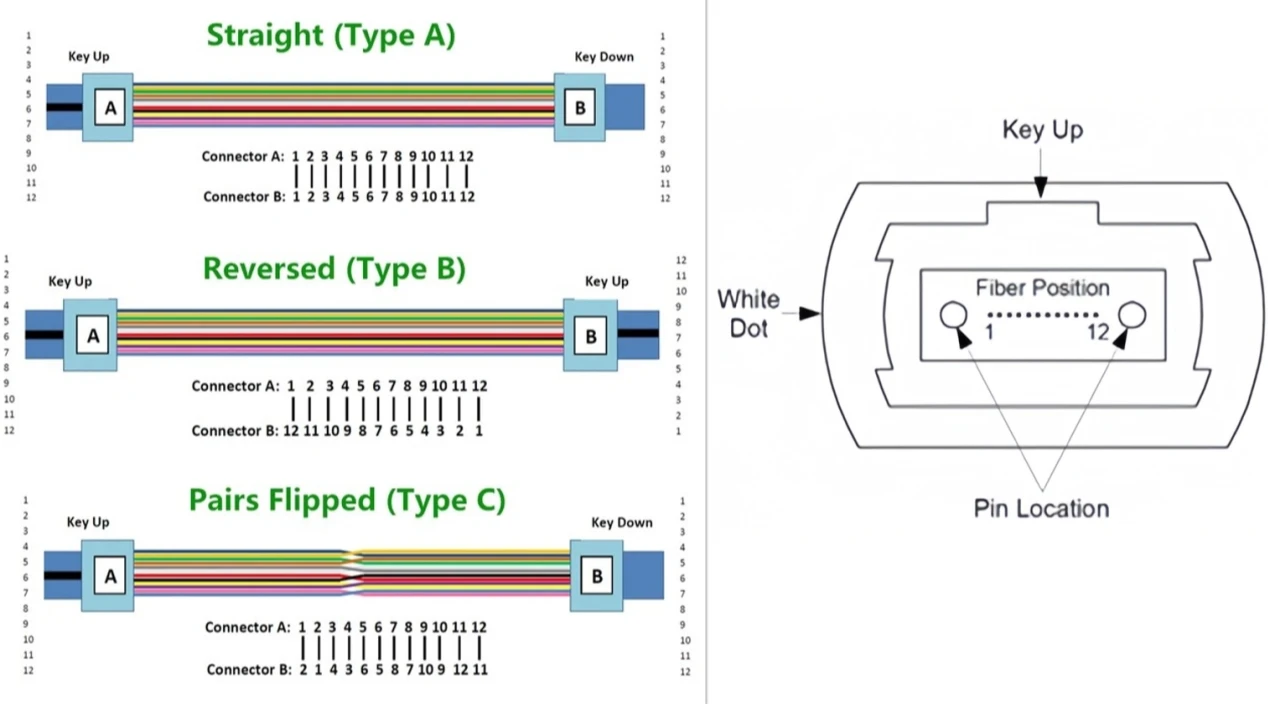
Illustration of MPO/MTP polarity types A, B, and C, showing fiber mapping for straight-through, crossed, and pair-flipped configurations.
Applications of MPO/MTP in Modern Networks
MPO/MTP excels in high-bandwidth environments. In data centers, they support spine-leaf architectures, connecting switches with transceivers. A 24-fiber MPO/MTP trunk can handle 200G bidirectional, reducing cable volume by 80% compared to single-fiber setups.
In telecom, MPO/MTP aggregates traffic for 5G networks. In high-performance computing, they enable fast interconnects for supercomputers. Enterprise networks use MPO/MTP cassettes for scalable cabling, supporting upgrades from 10G to 400G.
Visualize MPO/MTP harnesses powering server racks.
| Application | MPO/MTP Role | Benefits | Example Use Case |
|---|---|---|---|
| Data Centers | Trunk & breakout cabling | Space savings, scalability | High-speed uplinks |
| Telecom | Traffic aggregation | Low latency for 5G | Network fronthaul |
| HPC/AI | Parallel optic links | High throughput | AI compute clusters |
| Campus Networks | Structured cabling | Easy upgrades | 40G to 400G transitions |
Installation and Maintenance Best Practices
MPO/MTP installation demands precision. Work in a clean environment, using wipes and inspection scopes to check end-faces. Route cables with a bend radius >30 mm, securing with ties.
Steps:
Planning: Map polarity and select appropriate MPO/MTP cables.
Termination: Align keys and push until latched.
Testing: Verify insertion and return loss with specialized testers.
Labeling: Mark connectors with port numbers.
Maintenance includes regular cleaning with dry wipes and alcohol, using protective caps. For MTP, field polishing extends connector life.
Industry Common Problems and Solutions
Problem 1: Polarity Mismatches
Polarity errors, affecting 20-30% of MPO/MTP installs, cause link failures in high-speed systems.
Solution (100 words): Simulate links with polarity management tools before installation, ensuring Type A trunks pair with Type B patch cords. Use color-coded boots and automated testers to verify all fibers. Post-install, use reflectometers for end-to-end mapping. Train teams on polarity standards and audit quarterly. Labeled cassettes provide visual clarity, reducing errors by 90% and minimizing downtime to under 15 minutes.
Problem 2: High Insertion Loss from Contamination
Dust or debris on MPO/MTP ferrules increases insertion loss, degrading high-speed performance.
Solution (98 words): Enforce strict cleaning protocols: use one-click cleaners before mating and store connectors with caps. Clean with dry wipes and alcohol, inspecting with microscopes. Reseat connectors if loss exceeds 0.5 dB and retest. Use elite-grade MPO/MTP connectors for persistent issues. Schedule bi-annual cleanings and control rack environments. This keeps insertion loss below 0.2 dB, enhancing link reliability.
Problem 3: Cable Bend Radius Violations
Tight bends in MPO/MTP cables cause signal loss, impacting performance.
Solution (99 words): Plan routes with >50 mm bend radii, using organizers and flexible cables. Verify radii during installation and monitor for vibrations. Test for losses >0.3 dB and reroute if needed. Train installers on cabling standards, preventing 70% of bend-related issues and ensuring 20+ years of cable life.
Conclusion
MPO/MTP connectors combine innovation and reliability, supporting high-speed networks from 40G to 800G. Their multi-fiber design reduces clutter and enables scalability, making them essential for modern infrastructure. By mastering polarity, cleaning, and installation, networks can achieve unparalleled performance.
Glossary
Ferrule: A sleeve aligning optical fibers in a connector.
Insertion Loss (IL): Power reduction when light passes through a connector, in dB.
Return Loss (RL): Reflected light back to the source, minimizing signal interference.
Multimode/Single-mode: Fiber types for short- or long-reach applications.
Transceiver: Device converting electrical signals to optical for network connectivity.
Reflectometer: Tool for analyzing fiber links by detecting reflections.
Parallel Optics: Transmitting data over multiple fibers simultaneously.