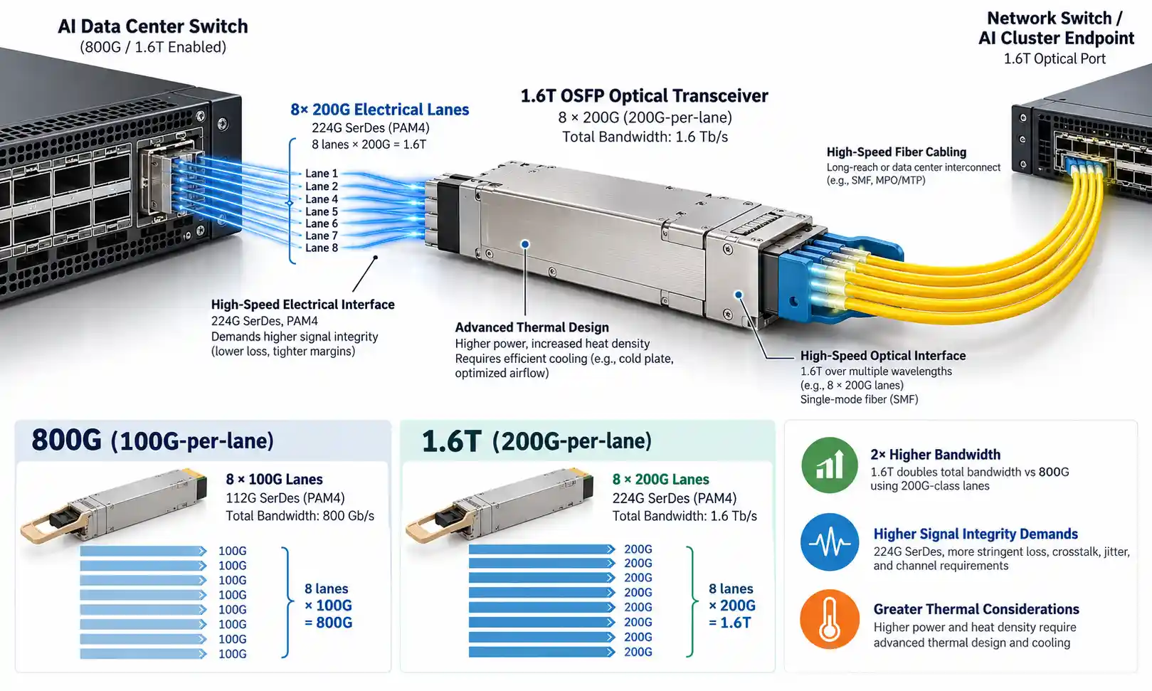
A CWDM link is ready for service only when the assigned wavelengths reach the correct ports, each optical path meets its loss budget, the receivers operate within their specified power range, and the intended traffic passes its acceptance test. A link-up indicator or a healthy total-power reading cannot establish all four conditions. Commissioning therefore requires separate checks of the channel map, wavelength-resolved power, passive-path insertion loss, and service performance.
The procedure below applies primarily to passive CWDM Mux/Demux links using wavelength-specific optical transceivers. Additional OADM nodes, single-fiber bidirectional designs, and active transport equipment require adjustments to the test points and acceptance plan.
What a CWDM Acceptance Test Needs to Prove
| Verification | Question to answer | Evidence to keep |
|---|---|---|
| Channel mapping | Does each transmitter feed the intended wavelength port and arrive at the intended far-end receiver? | As-built port and fiber map; confirmed wavelength-to-service assignments |
| Optical path loss | Does each tested wavelength pass through its assigned passive path within the allowed loss? | Measurement wavelength, reference method, insertion loss and design allowance |
| Received channel power | Is the channel present and is its receive power inside the transceiver's operating range? | Channel-resolved power readings and relevant transceiver limits |
| Service performance | Does the correct link carry the required traffic without unacceptable errors? | Interface status, error counters and project-defined traffic or bit-error test results |
These checks answer different questions. An optical time-domain reflectometer (OTDR) helps locate loss events along an accessible fiber path, but it cannot establish that the correct Ethernet service has been provisioned. Similarly, a wideband optical power meter can measure received light without identifying which of several simultaneous CWDM wavelengths is present.
Verify the CWDM Channel Map Before Measuring Loss
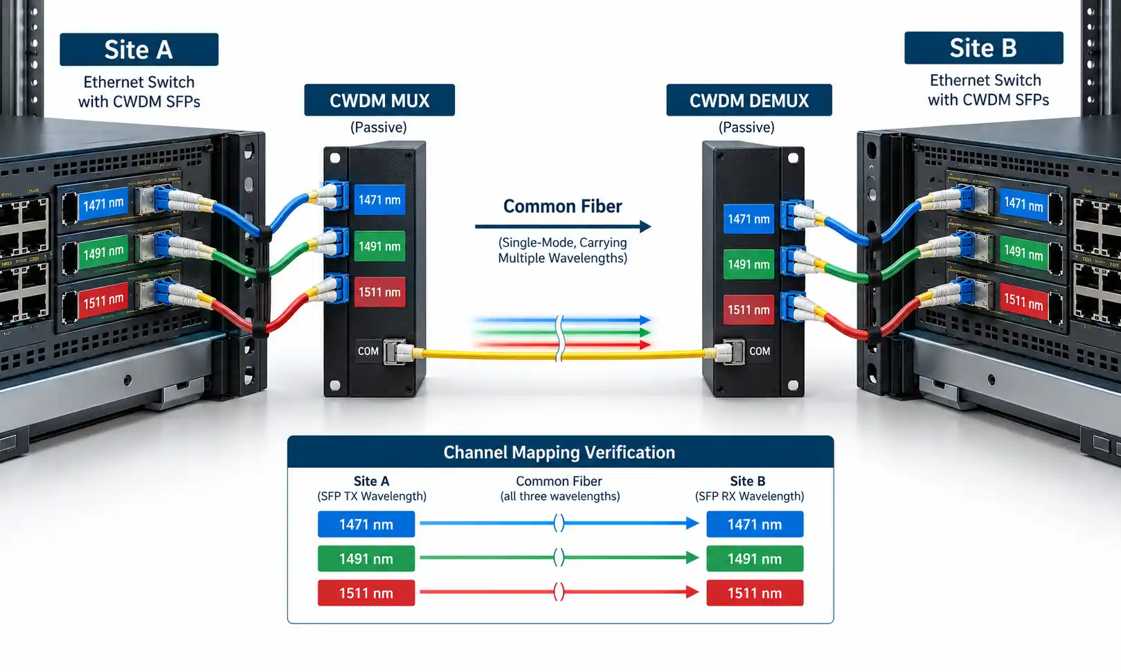
Start with the actual as-built diagram, not the colors of patch leads or the labels on a rack. For every circuit, record the local transceiver wavelength, local Mux port, common-fiber direction, remote Demux port and receiving interface. On a single-fiber system, document the wavelength assignments separately for each transmission direction. A dual-fiber channel plan cannot simply be copied into a bidirectional single-fiber design.
The ITU-T G.694.2 CWDM wavelength grid defines nominal center wavelengths with 20 nm spacing. The grid does not guarantee that every installed module supports every nominal channel or that two parts from different vendors have identical passband specifications. Check the optical interface and filter data sheets for the installed equipment.
Port names also matter. Channel, common, monitor, express and upgrade ports have different functions depending on the unit. A port that is physically accessible is not necessarily a permissible place to inject test light. Identify those functions on the hardware before testing; the distinction is covered in the site's overview of CWDM and DWDM Mux/Demux ports.
Channel-Mapping Record
| Field | What to enter |
|---|---|
| Service ID | Unique identifier for the circuit under test |
| Tx wavelength | Specified nominal wavelength of the transmitting module |
| Local Mux port | Physical port label and device identifier |
| Common fiber / direction | Fiber identifier and direction of transmission |
| Remote Demux port | Destination port label and device identifier |
| Rx interface | Receiving transceiver and equipment port |
| Result | Matched, mismatched or not yet verified |
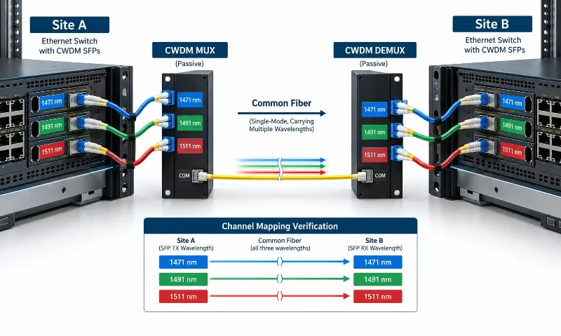
If a receiver sees no useful optical signal, first confirm that the installed CWDM SFP wavelength matches its assigned filter path. A wrong port can heavily attenuate the signal, but "zero light passes" is too absolute: the measured result depends on filter isolation, wavelength and the instrument's detection range.
Choose the Test Instrument for the Question
| Instrument | Suitable use | What it does not establish alone |
|---|---|---|
| Fiber inspection probe | Inspect connector end faces and assess contamination or damage | Wavelength identity or end-to-end link loss |
| Broadband optical power meter | Measure power from an isolated source or measure composite power where appropriate | Which CWDM wavelength is missing when several channels are present |
| Wavelength-matched source and power meter | Measure insertion loss for a defined passive CWDM path using a controlled reference | Correct service mapping beyond the measured optical path |
| CWDM channel power analyzer | Identify supported CWDM channels and their individual optical power levels | Precise laser spectral quality or proof that every remote service is correctly configured |
| Optical spectrum analyzer (OSA) | Investigate center-wavelength drift, spectral shape or suspected filter-edge problems where the required accuracy is available | Fiber-event location or traffic-layer performance |
| OTDR with suitable test wavelength | Locate and characterize accessible optical events; with a compatible CWDM OTDR, examine selected filtered paths | Channel-to-service assignment or application-level operation |
| Service or bit-error-rate tester | Verify transmission at the specified interface and test conditions | The physical cause of a failed optical loss test |

For example, the official EXFO FOT-5200 CWDM channel analyzer is designed to report channel-specific optical power. That is different from a broadband meter reading the total power of a multiplexed trunk. The correct instrument depends on whether the test is being performed on an isolated channel, a common port carrying multiple wavelengths, or an active receiver interface.
Step-by-Step CWDM Mux/Demux Commissioning
Where possible, complete fiber and passive-path testing before enabling the traffic channels. If services are already active, use the controlled in-service procedure and equipment approved for that network; do not treat the following offline steps as permission to disconnect a live customer link.
Step 1: Confirm the Optical Design and Test Boundaries
Collect the approved channel plan, fiber route, transceiver data sheets, Mux/Demux or OADM insertion-loss specifications, connector types and acceptance criteria. Mark the exact measurement reference planes. Decide whether the test covers only the passive device, the complete passive path or the installed transmitter-to-receiver link. The interpretation of a power measurement changes with those boundaries.
Step 2: Inspect the Connectors Before Mating Them
Inspect both sides of the connection, clean contamination with a method suitable for the connector and reinspect before mating. Also check reference test cords and accessible instrument interfaces. Dirt on a reference lead can be mistaken for excessive Mux loss. The Fiber Optic Association's connector inspection guidance explains why connectors should be checked before testing and connection.
A suitable fiber end-face inspection instrument helps reveal contamination and physical damage. Do not assume a connector is clean merely because it has been stored with a dust cap.
Step 3: Characterize Any Available Dark Fiber
Before inserting the passive CWDM units, or when an isolated segment can be made available, check fiber continuity and relevant events using an appropriate standard OTDR and test plan. Record wavelength, fiber type, direction, launch and receive cords where used, and the test settings. This establishes whether a fault existed in the underlying fiber plant before the wavelength filters were added.
If a Mux/Demux has already been fitted, determine whether the test port and OTDR wavelength can traverse the required filters. The site's general explanation of testing fiber optic cables with an OTDR provides background on ordinary fiber characterization; the filtered-path requirements are addressed below.
Step 4: Confirm the Installed Patch Route
Trace each patch cord from the source equipment to the correct wavelength port, then verify the common fiber and the corresponding destination route. Compare the physical connections against the channel map. In systems with multiple cabinets, confirm patch-panel and enclosure identifiers at both ends; matching wavelength labels are not enough if the common fibers have been crossed.
Keep the physical routing check separate from optical acceptance. A correctly labeled lead can still contain a dirty connection or an unexpected splice loss. If the assembly layout is uncertain, reconcile it with the installation record rather than repeating the basic CWDM Mux/Demux installation procedure.
Step 5: Verify Each Active Wavelength and Its Power
After the planned channels are enabled, inspect the authorized monitoring point or receiver-side test point using an instrument that can distinguish individual CWDM wavelengths. Confirm that each expected channel is present and compare its measured power with the documented operating range and measurement-port attenuation. A channel analyzer reading at a monitored common port does not, by itself, prove that the correct far-end service interface receives the signal.
Step 6: Measure the Passive Path Loss
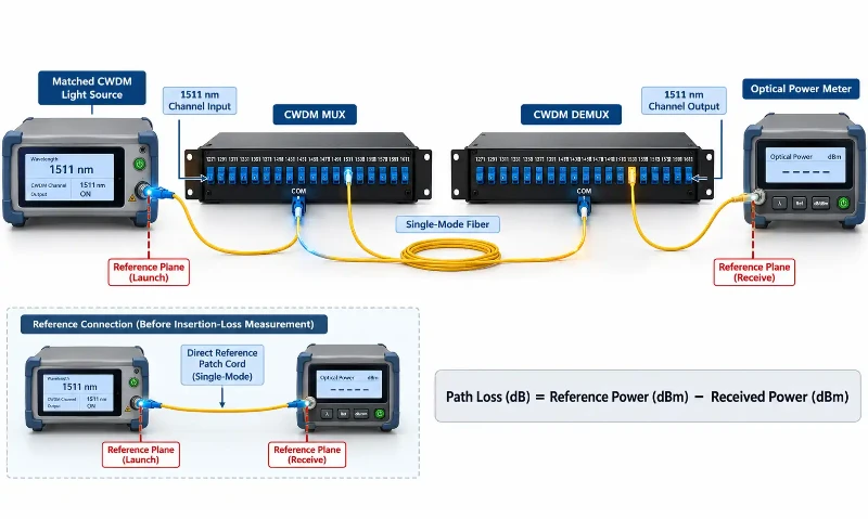
On an isolated path, set a documented optical reference using compatible test cords and a source whose wavelength falls within the channel's supported passband. Measure the end-to-end insertion loss using the same wavelength and reference method. Where the Mux/Demux has several channel ports, repeat the test for each commissioned wavelength rather than treating one channel as representative of the entire unit.
Step 7: Check Receive Power and Service Operation
Compare the measured or properly calibrated receive power with the transceiver's specified sensitivity and maximum permitted receive power. Optical margin must be evaluated against the actual interface specification, not a universal allowance. Then verify the correct switch or transport ports, interface speed, alarms and error counters. Carry out BER or traffic testing for the duration and conditions required by the project or service acceptance plan.
Step 8: Save a Repeatable Baseline
Keep the channel map, measurement references, instrument models, calibration status, wavelength, power results, insertion loss, OTDR files where relevant, service-test results and the date of acceptance. These records are most useful when they can be compared with a later test performed at the same reference planes and wavelengths.
How to Measure Insertion Loss for Each CWDM Channel
There are two different calculations in a CWDM turn-up test: measured passive insertion loss and available optical power budget. The first is a property of the tested optical path. The second tells you whether the selected transceiver pair has enough usable power range for that path.
Measured path loss (dB) = Referenced input power (dBm) − Measured output power (dBm).
This difference is meaningful only when the source, meter and reference planes are defined and the test wavelengths are appropriate. Use the relevant test method to account for test-cord connections included in the measurement. A transceiver's diagnostic-monitoring reading may help operational troubleshooting, but it is not automatically equivalent to a calibrated insertion-loss measurement.
For planning, the expected path loss is the sum of fiber attenuation at the specific CWDM wavelength, the Mux and Demux losses for that channel, connector and splice allowances, and any other optical elements in the actual route. A CWDM Mux/Demux data sheet should identify insertion loss under its specified conditions. Do not use the same assumed loss for every channel, channel count or chassis design.
On a route that includes a CWDM OADM, include the appropriate express-through, add or drop path loss for the particular service. Those paths are not interchangeable. The worst-case path may be a lower-wavelength fiber span on an older cable, a higher-loss filter path or a combination of several components; it cannot be selected merely by choosing the highest or lowest channel number.
Worst-case received power (dBm) = Minimum specified transmitter power (dBm) − Maximum expected path loss (dB).
Compare this result with the receiver's specified minimum power and also check the high-power case against receiver overload. Use the project's required engineering margin. There is no universal CWDM rule that every path must reserve exactly 2 dB or 3 dB, and no universal rule that each Mux contributes 3.5 dB.
Can an OTDR Test Through CWDM Filters?
A conventional 1310/1550 nm OTDR remains useful on a dark, accessible fiber segment. It is not a substitute for a wavelength-matched instrument when the test must pass through a particular CWDM Mux/Demux filter. Whether any test pulse reaches the remote section depends on the instrument wavelength, the actual filter passband, the port selected and the path topology.
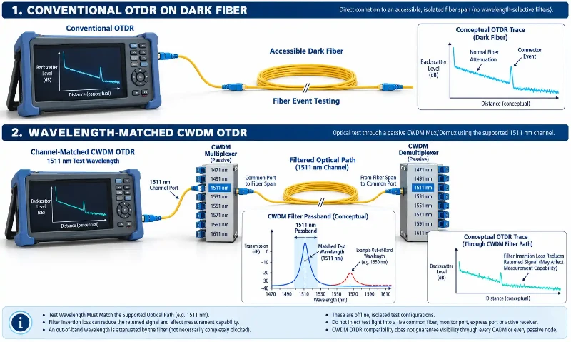
A purpose-built CWDM OTDR can select wavelengths corresponding to installed channels and characterize supported filtered paths. The EXFO 740C xWDM OTDR specifications, for instance, document wavelength-selective CWDM testing and instrument-dependent range, pulse-width and dead-zone specifications. The equipment specification-not a generic rule-determines the available settings.
Filter insertion loss reduces returned signal strength and can make downstream events harder to resolve. Increasing pulse width may improve the usable signal-to-noise ratio, but it also reduces the ability to distinguish nearby events. Choose pulse width, range and averaging for the actual path, then review reflective events and dead zones. An automated event map can assist interpretation; it cannot determine from the OTDR trace alone that a connector is dirty.
For troubleshooting, compare the OTDR findings with the channel loss results. A discontinuity located beyond the Mux may explain several failed wavelengths sharing one common fiber; an isolated single-channel problem is more likely to require checking that channel's patches, optics and filter path first. Neither pattern is conclusive without further tests.
Testing an In-Service CWDM Network
Do not inject a test signal into a live common fiber, monitor port, express port or unused wavelength simply because that wavelength is not assigned to a customer. The safety of a test depends on the device's internal optical path, filter isolation, source power, live receiver limits and the approved maintenance procedure.
Passive monitor taps may support nonintrusive observation of channel power when used with suitable instruments. Their tap loss must be taken from the device specification before a reading is interpreted. A monitoring port is not automatically an injection port. Likewise, an express or upgrade port may connect directly to the common route and may expose active receivers to an unsuitable signal.
Some compatible CWDM OTDR systems support testing a dark, isolated channel while other wavelength channels remain active. Such a test is permissible only within the manufacturer's stated conditions, including the required channel isolation and any disconnection of equipment at the far end. An in-service-capable instrument does not make every topology or port safe to test.
Before work begins, identify all live services, confirm the permitted test access point, review the instrument and passive-device instructions, and obtain the necessary maintenance authorization. If those conditions cannot be established, isolate the affected circuit or arrange an outage window. Observe appropriate optical safety practices and never inspect an energized fiber end directly.
Common CWDM Test Failures and What to Check
| Observed result | First check | Possible explanation and next action |
|---|---|---|
| No power on a single assigned channel | Transceiver wavelength, Tx status, channel port and patch route | Incorrect port or wavelength, disabled transmitter or interrupted path; confirm the source before replacing passive hardware. |
| Total trunk power is present but one service is down | Channel-resolved power and remote interface mapping | The expected wavelength may be absent or routed elsewhere; a broadband total-power reading cannot distinguish it. |
| Excessive loss on one wavelength | Test reference, end faces, channel path and product loss specification | Connector contamination, incorrect filter path or a wavelength-dependent fault; repeat a correctly referenced measurement. |
| Several channels fail together | Common fiber, shared connectors and common Mux/Demux path | A fault in a shared section may affect multiple channels; isolate the common plant before investigating individual optics. |
| A channel changes with equipment temperature | Module operating conditions, wavelength specification and measured spectrum where appropriate | Possible transmitter drift or marginal passband alignment; compare results with the actual optic and filter data sheets. |
| OTDR trace stops at a passive module | OTDR wavelength, test port, filter passband and path loss | Test light may be attenuated by the filter or fall outside available dynamic range; select a validated test configuration. |
| Acceptable optical power but excessive service errors | Receiver diagnostics, interface settings and service-layer counters | Potential transceiver, interface or transport problem; proceed with the approved service-test method. |
If suspected laser drift is involved, use an instrument with the wavelength accuracy needed for the module specification and compare measurements at the relevant operating temperature. CWDM lasers and filter products do not share a single universal drift tolerance. The measured center wavelength alone should not be treated as evidence that the optic must be replaced without checking the complete interface requirements.
CWDM Commissioning Checklist and Acceptance Records
Acceptance criteria should come from the approved design, transceiver and passive-component specifications, and the relevant project test standard. The purpose of a commissioning report is to make every result traceable, not to substitute a generic threshold for those requirements.
| Test item | Record | Acceptance basis |
|---|---|---|
| Channel map and direction | Service ID, nominal wavelength, local and remote ports, fiber ID | Approved as-built channel plan |
| Connector inspection | Inspected interfaces and results, with evidence where required | Approved connector inspection criteria |
| Passive path insertion loss | Reference method, wavelength, test boundaries, measured loss | Path-specific design budget and component specifications |
| Channel optical power | Measurement location, observed wavelength and power | Transceiver receive range, tap correction and test uncertainty as applicable |
| OTDR characterization | Trace file, wavelength, distance settings, event notes and direction | Project fiber acceptance criteria and supported instrument method |
| Service verification | Interface type, speed, alarms, error counters and test duration | Approved service and BER or traffic-test plan |
| Handover | Date, instrument IDs, calibration status, tester and exceptions | Complete reproducible acceptance package |
A project may require a specific receiver margin, splice limit, reflectance limit or BER-test duration. Those are valid when stated in its acceptance specification; they should not be copied from an unrelated CWDM installation. Current ITU-T G.695 optical-interface specifications also demonstrate why older statements describing 2.5 Gbit/s as a universal CWDM maximum are no longer suitable. The applicable interface and application code still need to be identified for the equipment being commissioned.
Frequently Asked Questions
How do you test a CWDM Mux/Demux?
Check the channel-to-port map, inspect and clean connectors, use a suitable wavelength-specific source to measure each passive path, and verify the individual channel powers. Confirm that the receiving interfaces meet their optical specifications, then complete the required service test. Save the reference method and channel-by-channel results.
Can an ordinary optical power meter identify a missing CWDM wavelength?
Not when it measures the composite power of multiple simultaneous wavelengths. It reports combined power rather than identifying the missing channel. A CWDM channel analyzer or suitable spectral instrument is needed for wavelength-resolved verification. A compatible ordinary power meter can still measure a properly isolated single-wavelength signal.
Can you use a 1310/1550 nm OTDR through a CWDM Mux?
Only if the particular test wavelength and optical path are supported by the installed filters and the instrument has sufficient performance. A standard OTDR is useful for accessible dark fiber, but may be blocked or heavily attenuated when testing through a CWDM channel port. A qualified wavelength-selective OTDR is generally more appropriate for testing specified channels through passive filters.
Why does one CWDM channel show higher loss than the others?
The channel may pass through a different filter path or encounter greater wavelength-dependent fiber attenuation. Dirty connectors, mismatched port assignments, a marginal optic or a measurement-reference error can also cause a discrepancy. Verify the test setup and channel map before attributing the problem to the Mux/Demux itself.
Can CWDM testing be performed without interrupting live services?
Some monitoring measurements can be performed on active systems, and certain instruments support testing isolated dark channels while other channels remain live. The permitted method depends on the passive device, the test wavelength, equipment isolation and network authorization. Do not inject a source through a monitor or express port without a manufacturer-approved test configuration.