The MPO adapter functions as a passive alignment interface enabling the mating of two MPO connectors within high-density fiber optic infrastructure. Unlike single-fiber solutions, MPO systems demand exceptionally tight mechanical tolerances-we're talking micron-level precision across 12, 24, or even 32 fiber channels simultaneously. The adapter's internal sleeve mechanism must maintain positional accuracy within ±0.5μm to achieve acceptable insertion loss figures, typically below 0.35dB for singlemode applications. This requirement becomes exponentially more challenging as channel counts increase.

The Alignment Problem Nobody Talks About
Here's what most spec sheets won't tell you: the relationship between lateral offset and optical loss isn't linear. A 0.5μm lateral displacement might give you 0.1dB loss-tolerable. Push that to 1.0μm, and suddenly you're at 0.4dB. Double it again to 2.0μm? Now you're staring at 1.5dB, which basically kills your link budget for any reasonable transmission distance.
The guide pin mechanism does the heavy lifting here. Two precision pins (0.70mm diameter, tolerance of ±0.001mm) on one connector mate with corresponding holes on the opposing connector. The adapter sleeve guides this engagement. Sounds simple enough.
It isn't.
The pin-to-hole clearance runs about 0.01-0.012mm. Too tight and insertion becomes problematic-users force the connection, pins bend, end faces crash together. Too loose and your twelve fibers never quite line up properly. Every single mating event stresses this interface.
Insertion Loss: Breaking Down the Numbers
| Parameter | Multimode Requirement | Singlemode Requirement |
|---|---|---|
| Maximum IL | ≤0.25dB | ≤0.35dB |
| Repeatability | ≤0.1dB | ≤0.1dB |
| Durability (500 cycles) | ΔIL ≤0.2dB | ΔIL ≤0.2dB |
Loss sources break into three categories. Fresnel reflection at the air gap between end faces-unavoidable physics. Beam divergence across that same gap-geometry problem. And misalignment in all three axes: lateral, longitudinal, angular.
Lateral offset dominates. For singlemode fiber with a 9.2μm mode field diameter, the core provides essentially zero margin for error. Multimode's 50μm core is more forgiving, which explains the tighter IL spec for MM systems despite the seemingly contradictory logic.

Return Loss and the APC Question
Return loss tells you how much light bounces back toward the source. For standard PC (physical contact) polish, you'll get around 20dB-adequate for multimode data links. UPC pushes this to 45dB through better surface finish. APC, with its 8-degree angled end face, achieves 55dB or better by directing reflections away from the fiber core entirely.
The catch with APC: you cannot mate APC connectors with PC/UPC adapters. The angle mismatch destroys both end faces. I've seen entire patch panels ruined because someone grabbed the wrong jumper cable. Color coding exists for a reason-green for APC, blue for UPC-but mistakes happen in dark data centers at 2 AM.
Reliability Testing Per GR-1435-CORE
Telcordia's GR-1435-CORE remains the industry benchmark. The environmental battery includes
Temperature cycling:
-40°C to +75°C, 21 complete cycles. Thermal expansion differentials between the phosphor bronze sleeve, PBT housing, and glass fibers create internal stresses. Adapters must maintain IL change below 0.3dB throughout.
Damp heat:
75°C at 90% relative humidity for 336-504 hours. This test catches inadequate material selection faster than anything else. Cheap polymers absorb moisture, swell, and lose dimensional stability.
Mechanical shock:
100g acceleration, 6ms duration, five shocks per axis. Simulates drop events and rough handling during installation.
The vibration test (10-55Hz, 1.5mm amplitude) often gets overlooked. Yet for adapters mounted in roadside cabinets or industrial environments, vibrational fatigue causes more field failures than temperature extremes.
The Contamination Reality
A 1μm particle sitting on a singlemode fiber core blocks roughly 1% of the optical path. Doesn't sound catastrophic until you realize that translates to approximately 0.1dB loss-per contaminated fiber. Multiply across twelve channels, add connector aging effects, and your "0.35dB max" adapter suddenly measures 0.8dB.
Particles above 9μm-roughly the singlemode core diameter-can cause complete channel failure.
IEC 61300-3-35 defines inspection zones with specific defect allowances
Zone A (core, 0-25μm): Zero defects permitted. None. A single scratch here fails the connector.
Zone B (cladding, 25-120μm): No scratches ≥3μm, no contamination ≥2μm
Zone C (adhesive, 120-130μm): Slightly relaxed limits
Zone D (contact, 130μm+): No defects exceeding 10μm
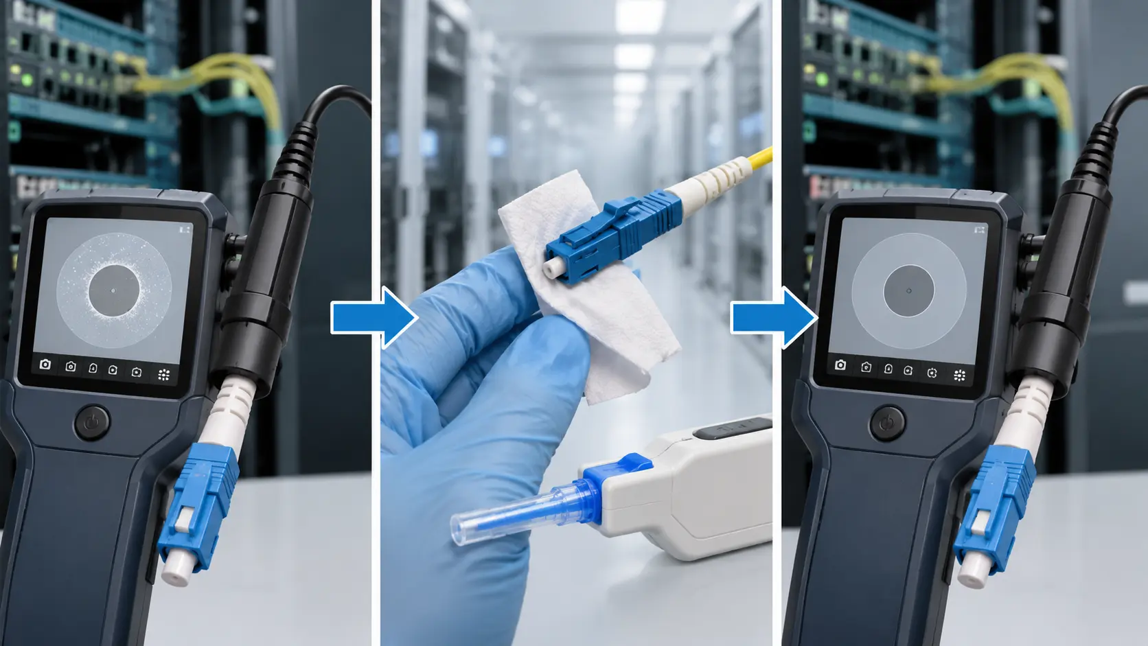
Cleaning protocol matters enormously. Dry wipe first using lint-free cloth or specialized MPO cleaning sticks. If contamination persists, 99% IPA applied sparingly, followed by dry wipe, followed by re-inspection. Never insert a connector without verifying end face cleanliness. The adapter's internal sleeve accumulates debris over time and transfers it to every connector that passes through.
Polarity Configurations
Three standard polarity methods exist, and mixing them causes link failures that are frustratingly difficult to diagnose

Type A (Key-up to Key-up): Straight-through fiber mapping. Position 1 connects to position 1.
Type B (Key-up to Key-down): Fiber positions flip. Position 1 connects to position 12. Most common in data center trunk cables.
Type C: Pair-wise flip-adjacent fiber pairs swap positions.
The adapter must match the system polarity design. A Type A adapter in a Type B system means your transmit fibers connect to the wrong receive ports at the far end. Ethernet protocols don't care; the link fails, full stop.
For 40G SR4 and 100G SR4 transceivers using eight fibers, the unused positions (5-8 in a 12-fiber array) sometimes cause confusion. The transceiver pinout, not the adapter, determines which fibers carry traffic.
Material Selection Trade-offs
Adapter housings come in two flavors: thermoplastic (PBT, PPS) or die-cast zinc alloy.
Plastic housings dominate data center deployments. Lower cost, lighter weight, adequate for controlled environments. PBT offers good chemical resistance and dimensional stability up to 60°C continuous operation.
Metal housings make sense for telecom outside plant, industrial installations, and anywhere EMI shielding matters. The mass also provides better vibration damping. Downside: cost roughly doubles, and corrosion becomes a consideration in coastal or high-pollution environments.
The internal alignment sleeve is almost always phosphor bronze with nickel plating. Ceramic sleeves exist for ultra-high-precision applications but rarely justify their cost premium for adapter use. The sleeve sees less wear than connector ferrule sleeves since it only guides initial engagement rather than providing ongoing alignment.
Durability Curves
Real-world durability follows a bathtub curve. Initial mating events may show slightly elevated loss as surfaces burnish. Loss stabilizes for several hundred cycles. Beyond 500-700 cycles, wear accumulation causes gradual degradation.
Manufacturer specifications claiming 1000+ cycle durability aren't lying, but the fine print matters. "Durability" typically means the adapter hasn't mechanically failed-it still latches, connectors still insert. Whether it still meets optical specifications is a separate question.
For patch panel positions seeing daily activity, budget for adapter replacement every 2-3 years. Trunk interconnects touched once during installation last essentially forever.
Practical Selection Criteria

For hyperscale data centers running 100G/400G SR optics:
- 12-fiber or 24-fiber MPO
- Type B polarity (verify against cabling plant design)
- Low-loss grade: IL ≤0.35dB
- Plastic housing acceptable
- High cycle count if used in meet-me rooms

For telecom transport applications:
- Singlemode APC where return loss matters
- Extended temperature range (-40°C to +85°C rated)
- Metal housing for outdoor installations
- Consider IP-rated options for environmental sealing

For enterprise campus networks:
- Standard commercial grade typically sufficient
- Focus on proper labeling and polarity management
- Stock spare adapters for quick replacement
Field Troubleshooting
When insertion loss exceeds specifications:
First, clean everything. Both connector end faces and the adapter's internal surfaces. Use proper MPO cleaning tools-the geometry prevents standard LC/SC cleaning methods from working.
Second, inspect under magnification. 200x minimum, 400x preferred. Look for scratches crossing the fiber cores, embedded contamination, chips at the fiber-to-ferrule boundary.
Third, try a known-good reference cable through the suspect adapter. If the reference cable tests fine, your original cable has the problem. If the reference cable also shows high loss, the adapter needs replacement.
High return loss (meaning low reflected power) in an APC system usually indicates either contamination or an end face geometry issue-the 8-degree angle has degraded through repeated mating or physical damage.
Intermittent connections almost always trace to mechanical issues: worn latching mechanisms, cracked housings, or bent guide pins on the connector (not the adapter, strictly speaking, but the adapter gets blamed).
What the Standards Actually Require
- IEC 61754-7 defines the MPO interface mechanically. Dimensions, tolerances, materials-everything needed for interoperability between manufacturers.
- IEC 61753-1 covers performance requirements across environmental conditions. This is where the temperature, humidity, and mechanical test parameters live.
- TIA-604-5 (FOCIS 5) provides the North American equivalent, with some parameter differences that occasionally cause confusion when mixing components from different regional suppliers.
- GR-1435-CORE from Telcordia adds telecom-specific reliability requirements beyond the IEC baseline.
- Grade classifications (A, B, C) originated as a way to bin production output by loss performance. Grade A (≤0.35dB) commands premium pricing but ensures adequate link margin. Grade B (≤0.75dB) works for shorter links or systems with margin to spare. Grade C exists but seeing it in production deployments suggests procurement problems.

Emerging Developments
The push toward 400G and 800G Ethernet drives demand for higher fiber counts. 32-fiber MPO connectors exist but adapter availability remains limited compared to 12-fiber and 24-fiber versions. The mechanical complexity of aligning 32 fibers to micron-level precision across temperature ranges pushes manufacturing capabilities.
Some vendors promote field-installable MPO connectors, reducing dependence on pre-terminated trunk cables. The adapter's role remains unchanged, but the quality variance of field-terminated connectors creates new challenges for consistent system performance.
Parallel optics (SR4, SR8) continue expanding, but the industry also explores single-fiber high-speed solutions using advanced modulation. If 800G single-lambda transmission becomes practical, MPO's density advantage diminishes-though not enough to threaten its position in structured cabling architectures.
Integration of RFID or similar tracking into adapter assemblies enables automated asset management. Useful for hyperscale operators managing millions of fiber connections; overkill for smaller deployments.
The fundamental physics of fiber alignment aren't changing. Whatever form factor succeeds MPO will face identical challenges: micron-level precision, contamination sensitivity, and the tension between density and reliability. Current MPO technology represents a mature, well-understood solution that works-provided you respect its requirements for cleanliness, proper mating procedures, and periodic inspection.