Existing GPON PLC splitters can often stay in service during a 50G-PON upgrade. A splitter does not process PON protocols, but reuse is acceptable only when its wavelength performance, measured insertion loss, reflectance, physical condition and the complete optical distribution network (ODN) meet the requirements of the selected 50G-PON equipment. A working GPON connection does not prove that the same path will pass a new optical budget. Missing records call for testing or further qualification, not automatic replacement. If the path fails after recoverable faults have been corrected, the operator must change the splitter, reduce other losses or revise the network design.

Can an Existing GPON PLC Splitter Support 50G-PON?
A planar lightwave circuit (PLC) splitter divides optical power between subscriber branches. It does not recognize GPON, XGS-PON or 50G-PON frames. That makes reuse possible, but it does not make every installed splitter suitable. The optical interface, operating wavelengths, permissible optical path loss (OPL), coexistence arrangement and condition of each branch determine whether an upgrade can proceed.
The ITU-T G.9804.1 requirements for higher-speed PON address the use of existing ODN infrastructure and split ratios in network evolution. A 1:64 split may be part of a 50G-PON design, subject to the total loss budget; it is not a guarantee that every old 1:64 installation is reusable.
For optical interfaces, use the applicable edition and amendments of ITU-T G.9804.3. Its February 2026 Amendment 3 updates 50G-PON physical-layer provisions. Current planning should not treat the deprecated 12.5 Gbit/s upstream option as a new deployment choice. The relevant upstream configurations and optical requirements must be taken from the selected equipment specification and applicable standard.
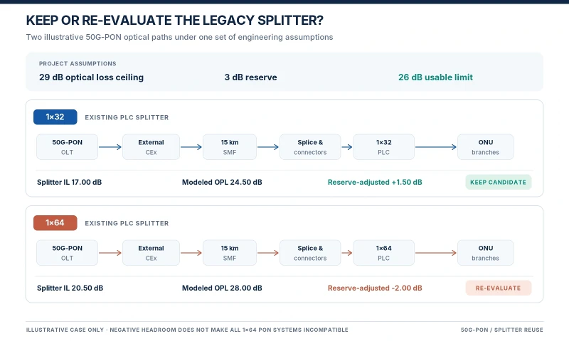
Practical starting point: keep the existing splitter on the candidate list when its documented optical characteristics appear suitable and the cabinet and fibers are serviceable. Approve reuse only after the complete path has been checked against the actual deployment requirements.
What Must Be Verified Before Reusing a PLC Splitter?
Operating wavelengths and spectral response
Many single-mode PLC splitters are specified over a broad band such as 1260–1650 nm. That is useful evidence, but the printed range alone is not a 50G-PON compatibility certificate. Obtain the datasheet for the installed model, including insertion-loss performance over the wavelengths used by the proposed downstream, upstream and coexisting services. If the only available measurement is at 1310 or 1550 nm, do not assume the same loss at every 50G-PON operating wavelength.
Check the splitter's wavelength-dependent loss and any other wavelength-selective components in the ODN separately. A PLC splitter and a coexistence filter do different jobs; a broad-band splitter specification does not verify the passbands or isolation of the filter.
Insertion loss and the worst output port
Ideal equal splitting imposes a power division loss of 10 × log10(N), where N is the number of outputs. This is approximately 15.05 dB for 1×32 and 18.06 dB for 1×64. Actual devices add excess loss and may differ from port to port. Those theoretical figures must not be entered as the measured splitter loss in an acceptance calculation.
Use the maximum insertion loss specified for the exact model and grade during planning, then use calibrated measurements of the installed device or end-to-end paths for acceptance. Record the highest-loss branch instead of relying on an average. Loss uniformity, polarization-dependent loss (PDL) and wavelength-dependent loss should be checked against the manufacturer's verified specifications where they affect the project requirements. A high-loss output may need connector repair or splice work rather than immediate replacement of the entire splitter.
Reflections, connector condition and environmental rating
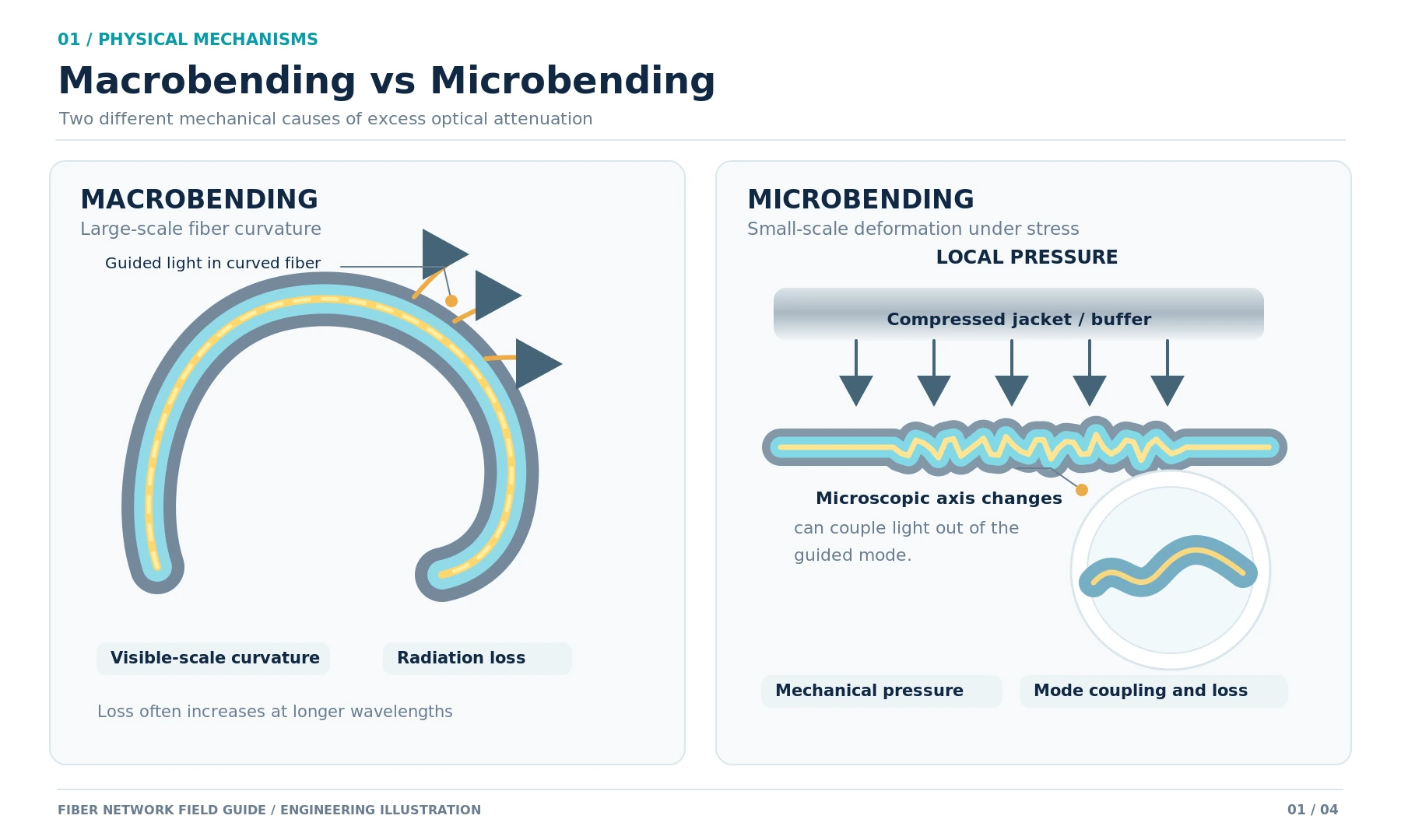
Inspect connector end faces, polish type, mating adapters and splice points. Contamination, damage or an unsuitable connector pairing can increase loss or reflection. APC connectors can offer lower reflectance than UPC connectors, but a move to 50G-PON does not, by itself, require every UPC termination to be replaced. Follow the equipment interface and optical return-loss requirements, and never mate APC and UPC end faces directly.
The cabinet environment also matters. Confirm that the actual splitter package, pigtails and enclosure are rated for the expected temperature, moisture and mechanical conditions. Do not assign every PLC product the same temperature rating or reject all older FBT devices using an assumed rating. Inspect the installed part and its documentation first.
Single-stage and cascaded splitting
A single 1×32 splitter and a cascaded 1×4 followed by 1×8 both serve 32 branches, but their actual losses need not be identical. Cascading adds device interfaces and may introduce extra splice or connector losses. Each branch requires its own accounting. For general design choices between one- and two-stage splitting, FOCC Fiber also covers FTTH splitting levels and ratios; the question here is whether the installed arrangement passes the new qualification requirements.
1×32 and 1×64 PLC Splitter Reuse: Two Qualification Examples
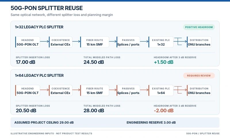
The examples below are illustrative engineering calculations, not FOCC Fiber factory test results or measurements from a deployed 50G-PON network. The assumed 29.0 dB project loss ceiling is used only to demonstrate the decision process. It is not a universal 50G-PON acceptance limit. Actual limits depend on the chosen OLT and ONU interfaces, OPL class, reference points and coexistence method. The downstream and upstream directions must each be assessed with their own equipment parameters.
Common assumptions for the two examples
- Fiber route: 15 km at an illustrative attenuation of 0.30 dB/km at the assessed wavelength, giving 4.50 dB.
- Combined connectors and splices on the assessed path: 2.00 dB, assumed rather than measured.
- External coexistence element on the assessed path: 1.00 dB, assumed from a hypothetical device specification and counted once.
- Project loss ceiling at the stated assessment endpoints, including that external element: 29.00 dB.
- Required engineering reserve: 3.00 dB. This is a project assumption, not a universal standard value.
- Splitter insertion loss: 17.00 dB for the illustrative 1×32 device and 20.50 dB for the illustrative 1×64 device.
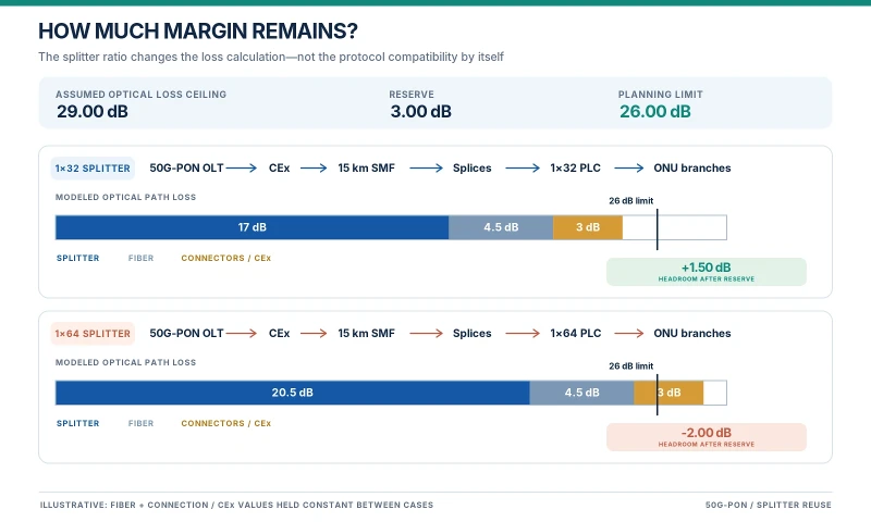
The modeled path loss is the sum of splitter loss, fiber attenuation, connection and splice loss, and the external coexistence element's loss. Remaining headroom is the project loss ceiling minus that path loss; reserve-adjusted headroom subtracts the required 3.00 dB reserve. Avoid adding the external element again if the selected equipment's published OPL figure or reference-point definition already accounts for it.
| Illustrative calculation | 1×32 path | 1×64 path |
|---|---|---|
| Splitter insertion loss | 17.00 dB | 20.50 dB |
| 15 km fiber loss | 4.50 dB | 4.50 dB |
| Connections and splices | 2.00 dB | 2.00 dB |
| External coexistence element | 1.00 dB | 1.00 dB |
| Modeled path loss | 24.50 dB | 28.00 dB |
| Assumed project loss ceiling | 29.00 dB | 29.00 dB |
| Headroom before reserve | 4.50 dB | 1.00 dB |
| Required reserve | 3.00 dB | 3.00 dB |
| Headroom after reserve | +1.50 dB | −2.00 dB |
Example A: 1×32 splitter with positive planning headroom
At the assumed 17.00 dB insertion loss, the 1×32 branch has 1.50 dB of headroom after the project reserve. That is a reason to continue qualification, not a final approval. The technician still needs to measure the worst output branch, confirm losses at the relevant operating wavelengths, check reflections and verify both upstream and downstream optical interfaces. A verified device record can then be compared against an available 1×32 ABS-packaged PLC splitter configuration when assessing replacement form factor and termination requirements. Do not treat the illustrative 17.00 dB figure as that product's certified specification.
Example B: 1×64 splitter with insufficient planning reserve
At the assumed 20.50 dB insertion loss, the 1×64 path has only 1.00 dB of headroom before the required reserve and falls 2.00 dB short afterward. The example fails the stated project planning criterion. It does not establish that every 1×64 splitter fails 50G-PON. Verify the actual losses and consider reducing avoidable connection loss, shortening the path where feasible, selecting a qualified optical configuration or redesigning the split arrangement before replacing hardware.
Where cabinet layout requires a rack-mounted device, the replacement assessment should compare the actual dimensions, pigtail routing and connector options against the 1×64 rack-mount PLC splitter configuration, subject to confirmation of the ordered model's current test data.
Both examples are incomplete without the selected transceivers. Check minimum and maximum permitted OPL, transmitter power, receiver sensitivity, overload and applicable reflectance requirements separately for each transmission direction. A path can exceed a maximum-loss requirement or fall below a minimum-loss requirement. Neither failure can be ruled out by the splitter ratio alone.
How Does GPON, XGS-PON and 50G-PON Coexistence Affect Reuse?
Operators often keep GPON and XGS-PON customers online while activating 50G-PON subscribers on the same fiber plant. The coexistence design therefore matters as much as the splitter itself. ITU-T G.9805 Amendment 2 (November 2025) describes coexistence arrangements and updated multi-generation optical interfaces.
| Coexistence method | What to check | Budget implication |
|---|---|---|
| External coexistence element (CEx) | Specified passbands, isolation, insertion loss by path and operating wavelength | Include its applicable path loss at the correct reference points; do not assume a fixed 1.5 dB for all devices. |
| Multi-PON module (MPM) | Supported PON generations, optical class, integrated filtering and vendor interface definitions | Use the MPM's specified interface and OPL criteria. Do not add an external-CEx allowance unless one is actually installed. |
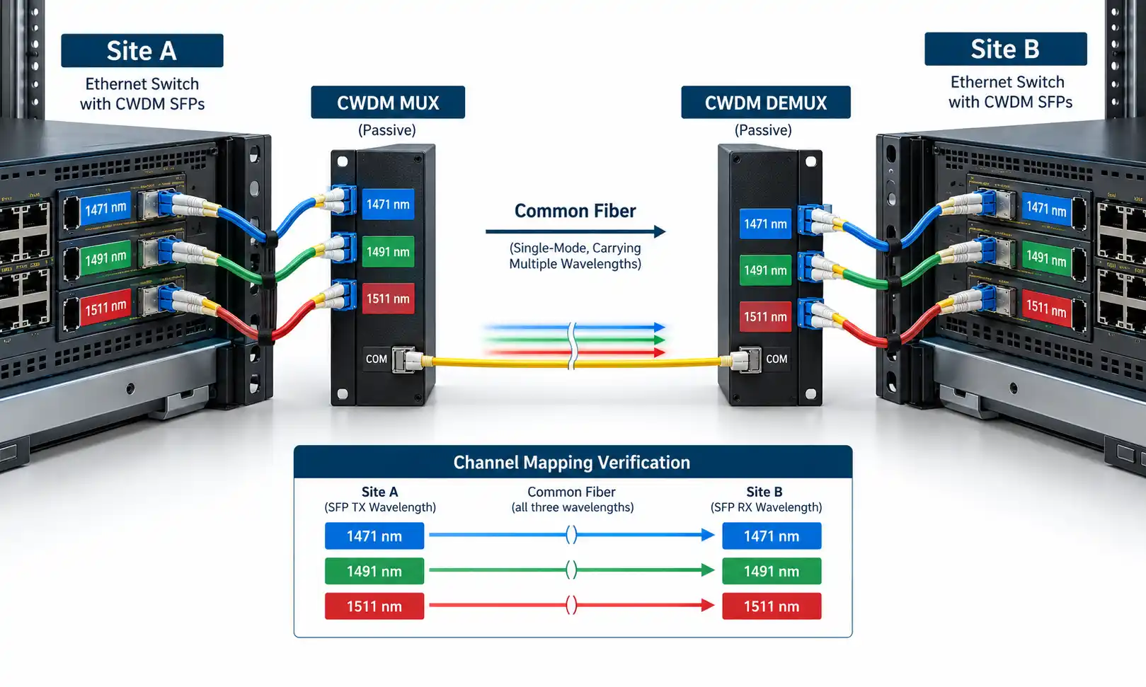
| Splitter-based coexistence | Combining/splitting topology, branch allocation, isolation and each affected power path | Account for the actual additional splitting and connection losses, not a generic filter penalty. |
Check whether the chosen wavelengths and filters can coexist with all services that will remain active. Verify isolation and out-of-band considerations using the relevant equipment and coexistence specifications. Reusing a broadband PLC splitter does not eliminate the need to qualify the rest of the shared ODN.
How to Test an Existing PLC Splitter Before Approval
Field qualification should produce records that another engineer can review. Work on a live PON requires an approved maintenance procedure and instruments suitable for the service wavelengths; testing must not interrupt active subscribers or expose equipment to inappropriate test signals.
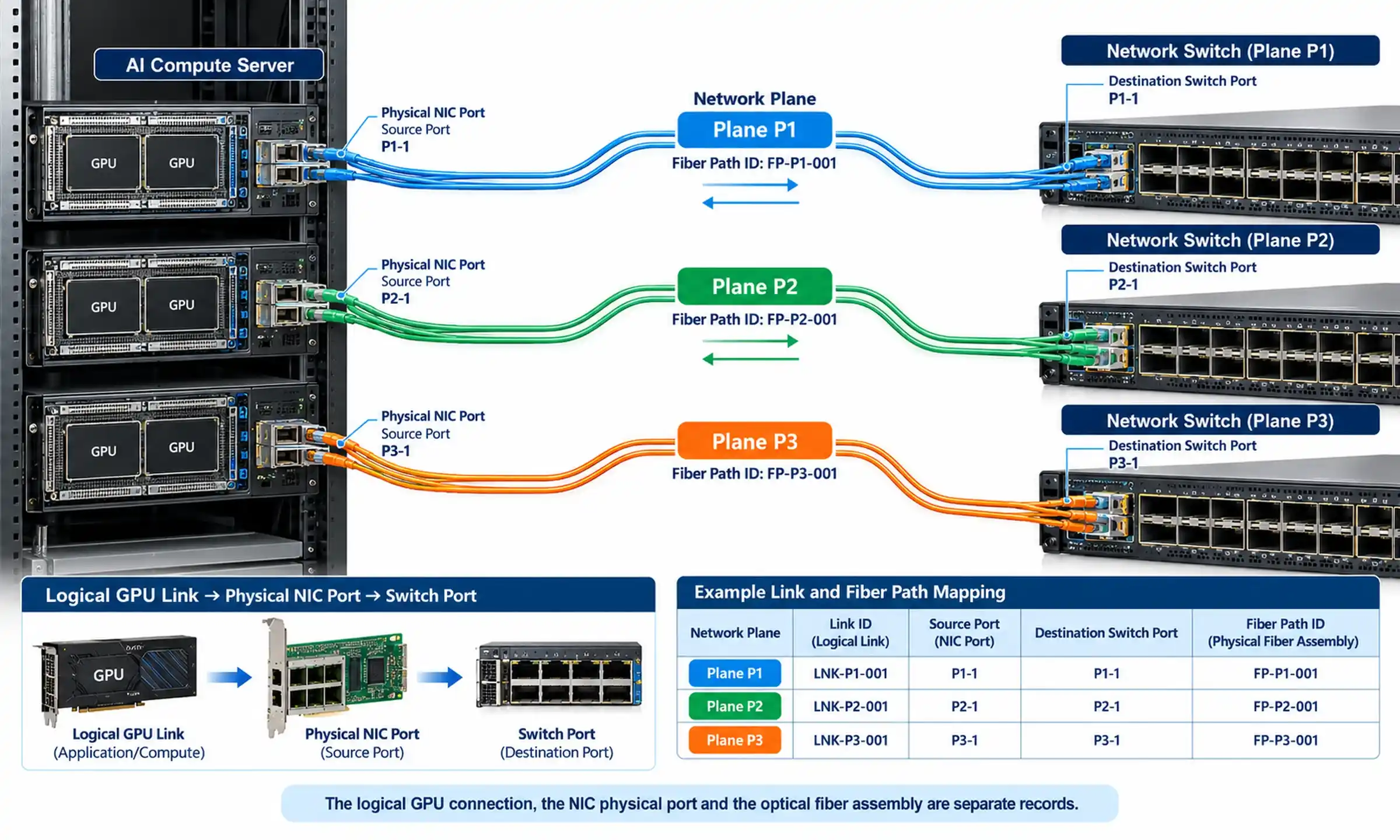
- Identify the asset. Record the enclosure location, splitter part number, split ratio, package, connector type, fiber route and any available batch or serial information. Where labeling is absent, record the uncertainty rather than inventing a model identity.
- Inspect and clean. Examine connectors with an appropriate inspection probe, clean as needed, and check pigtails, bends, closures and environmental damage. Reinspect after cleaning.
- Measure insertion loss. Use a calibrated optical light source and power meter or suitable loss-test equipment, with documented reference method and test wavelengths. Record each relevant output path and the worst-port result. Follow the component and project test procedures; IEC 61300-3-4:2023 describes attenuation measurements for passive optical components.
- Check reflectance where required. Compare connector and ODN optical return-loss evidence against the equipment limits. Do not infer compliance solely from APC or UPC labeling.
- Use OTDR for fault location. Locate bends, splices and abnormal events with an instrument and settings suitable for high-loss PON branches. Splitters produce complex traces that differ by direction; an OTDR trace alone does not replace calibrated insertion-loss results. The basic OTDR testing procedure provides additional context, while the Fiber Optic Association's FTTH testing guidance explains why splitter traces require special interpretation.
- Record conditions and compare. Keep instrument identification and calibration status, measurement date, wavelength, reference settings, test endpoints, output-port results and any repairs. Compare the evidence with the confirmed equipment OPL and project acceptance criteria.
Where a splitter cannot be isolated for component-level testing, the team may need a controlled outage or an approved alternative end-to-end test. The report should state which parts were directly measured and which rely on manufacturer documents or engineering assumptions.
Legacy PLC Splitter Reuse Qualification Matrix
Use the same assessment criteria across all candidate cabinets, but enter the project's actual acceptance limits and results. A passband printed on a datasheet, a loss estimate and a completed field measurement are different types of evidence; they should not be treated as interchangeable.
| Assessment item | Evidence required | Decision rule | Possible action |
|---|---|---|---|
| Operating wavelength | Verified model data and relevant wavelength test evidence | Suitable for every planned optical channel and coexistence path | Keep in assessment; obtain data or test if unknown |
| Worst-port insertion loss | Calibrated port-level or end-to-end measurements | Meets the approved OPL and engineering reserve requirements | Keep, repair loss events, or redesign |
| Uniformity and PDL | Model specifications and test evidence where needed | Within the relevant device and project limits | Investigate outlying ports before replacement |
| Reflectance and connectors | Interface specification, inspection and ORL/reflectance results as required | Compatible mating and optical performance | Clean, repair or change termination |
| Coexistence architecture | CEx, MPM or splitter-based design and optical specifications | Each affected path satisfies the selected system's requirements | Revise component choice or topology |
| Environmental condition | Package rating, cabinet inspection and damage records | Suitable for the installation and expected service conditions | Repair enclosure or replace failed hardware |
| Approval record | Completed measurements, identified equipment and authorized limits | All critical checks documented and accepted | Keep / Repair and retest / Further qualification / Replace or redesign |
Keep: the required evidence is complete and the actual system criteria are met. Repair and retest: a connector, splice or other recoverable fault is responsible for the loss. Further qualification: the model or measurements remain uncertain. Replace or redesign: the verified optical or mechanical requirements cannot be met after feasible corrective work.
What Buyers Should Specify for Replacement PLC Splitters
A failed reuse assessment should lead to a defined procurement requirement, not an order for the same split ratio with no supporting information. Before asking for a quote, give the supplier the conditions the new component must satisfy:
- Split ratio and optical requirement: 1×32, 1×64 or the required cascade, together with the maximum allowable loss for the component or applicable branch, and the wavelengths at which it must be verified.
- Verified device characteristics: applicable maximum insertion loss, uniformity, PDL, return loss or reflectance requirements, plus the requested factory test report and acceptance method.
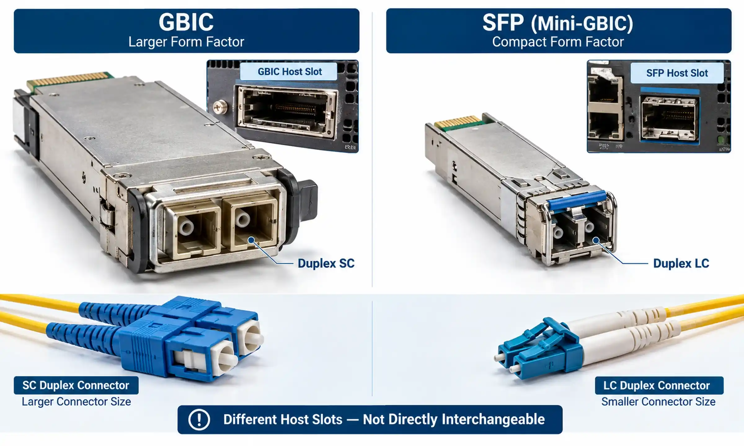
- Mechanical configuration: ABS, blockless, LGX, rack-mount or other suitable package; mounting space, pigtail length, fiber type and routing arrangement.
- Connector specification: connector family, UPC or APC polish as required by the actual interface, and the correct mating arrangement.
- Environment and quantity: operating-temperature and enclosure requirements, project location, planned quantity, delivery schedule and any sample approval process.
- System context: 50G-PON equipment, intended coexistence method, link length, current loss measurements and the reason the existing splitter was not approved.
FOCC Fiber offers several PLC splitter package and split-ratio options for comparison. Product listings are a starting point; the actual ordered part number, current datasheet, test conditions and ability to satisfy the project requirements must be confirmed before purchase. A new splitter with a lower nominal loss is not automatically the correct replacement if its connector, package or environmental rating is wrong.
Frequently Asked Questions
Can an existing 1×64 GPON splitter be reused for 50G-PON?
Yes, potentially. A 1×64 split is not disqualified solely by its ratio. Approval depends on the selected 50G-PON interfaces, the measured loss of the worst branch, the coexistence design and the required operating margin. A long or heavily connected 1×64 path may need loss reduction or redesign.
Does a 1260–1650 nm PLC splitter automatically support 50G-PON?
No. A broad operating band supports initial screening, but the installed model still needs suitable loss performance over the actual system wavelengths, acceptable reflections and a complete ODN budget that passes the specified requirements.
Is OTDR testing enough to approve the splitter?
No. OTDR testing is useful for finding fault locations, but an acceptance record also needs appropriate insertion-loss measurements, equipment limits and, where relevant, return-loss evidence. Splitter events can complicate OTDR interpretation.
Must a splitter be replaced when its original datasheet is missing?
Not necessarily. Identify the installed hardware if possible and perform an approved measurement and qualification process. Replacement becomes appropriate when the required performance cannot be demonstrated or the hardware fails the project's conditions.
Make the Reuse Decision Before Ordering Hardware
An existing PLC splitter should be retained when its condition and documented performance meet the selected 50G-PON deployment requirements. Where measurements show avoidable loss, repair and retest the affected part of the path. Replace or redesign only when the confirmed requirements still cannot be met. This approach avoids unnecessary replacement without accepting undocumented optical risk.
For a 50G-PON upgrade or PLC splitter replacement, send FOCC Fiber the existing splitter model, split ratio, connector and package details, available loss records, proposed OLT/ONU optical requirements, coexistence architecture and estimated order quantity. The team can review available component configurations and quotation requirements against the information supplied. Contact FOCC Fiber with your project specifications.