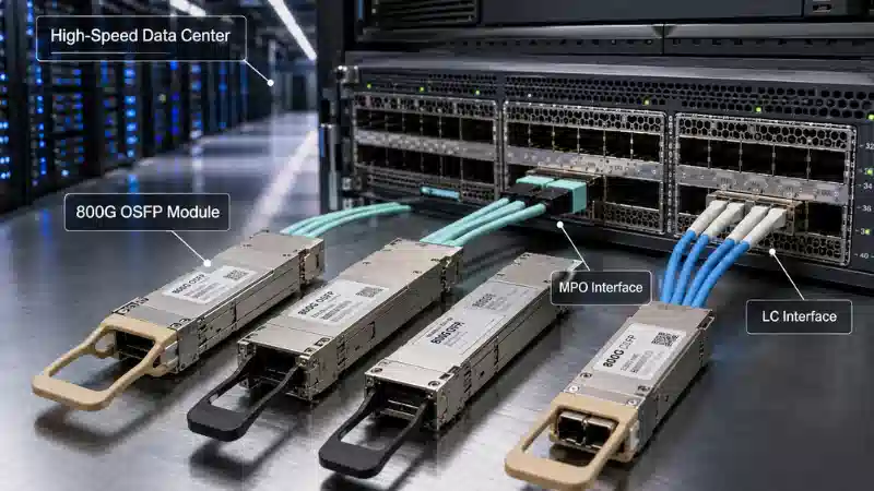
An 800G OSFP module is a hot-pluggable transceiver that carries an aggregate data rate of up to 800 gigabits per second through a compatible switch, router, network adapter, or accelerator platform. It is increasingly relevant to AI clusters, high-performance computing, and high-capacity spine-leaf fabrics where a 400G link can become a bandwidth bottleneck.
The label "800G OSFP" is not a complete specification. Two modules with that label may use different electrical lanes, optical interfaces, fibers, connectors, breakout modes, power levels, cooling structures, management applications, and protocols. Understanding this distinction is essential when moving from a general 800G Ethernet architecture to an actual bill of materials.
This guide explains how OSFP works, compares VR8, DR8, and 2×FR4 designs, and shows how to check cabling, thermal, CMIS, FEC, and host-platform compatibility before deployment.
What Is an 800G OSFP Module?
OSFP means Octal Small Form Factor Pluggable. "Octal" refers to eight high-speed electrical lanes at the host interface. A conventional OSFP800 Ethernet implementation commonly combines eight lanes operating at approximately 100G per lane, while newer platform-specific designs may use four 200G lanes.
The OSFP MSA module specification defines the mechanical envelope, host connector, electrical interface, power supplies, cage, and thermal framework. It provides a path from eight 50G lanes for 400G to eight 100G lanes for 800G and eight 200G lanes for 1.6T-class applications.
Key distinction: OSFP defines a module form factor and host interface. It does not, by itself, determine the protocol, optical reach, connector, fiber type, breakout map, or switch compatibility.
For a broader view of pluggable module families and lower-speed products, see FOCC's fiber optic transceiver category.
The Standards and Platform Layers That Must Match
A working 800G link depends on several layers. Problems arise when a buyer treats these layers as one interchangeable "800G standard."
| Layer | What It Determines | What It Does Not Guarantee |
|---|---|---|
| OSFP MSA | Physical size, host connector, electrical and thermal framework | Optical reach or switch acceptance |
| IEEE or protocol specification | Ethernet or other protocol behavior and PHY requirements | Module form factor or vendor coding |
| CMIS | Module identification, application selection, monitoring, and control | Support in every operating system or switch |
| Host platform | Port modes, firmware, FEC, power, cooling, and coding policies | Compatibility with any physically insertable module |
| Optical interface | Wavelengths, lane count, fiber, connector, and reach | Correct breakout configuration at the host |
IEEE Ethernet Specifications
The IEEE 802.3df task force completed its work when IEEE Std 802.3df-2024 was approved on February 16, 2024. The project includes high-speed Ethernet work relevant to 800 Gb/s and 1.6 Tb/s operation. IEEE specifies Ethernet behavior; it does not replace the OSFP mechanical specification.
CMIS Module Management
The OIF Common Management Interface Specification defines how a host can read module inventory, discover supported applications, configure data paths, monitor alarms, and manage module functions. CMIS improves interoperability, but the host firmware must still support the advertised application and data-path configuration.
This is why a module can be visible in inventory yet fail to establish a link. Recognition confirms management communication; it does not prove that port mode, FEC, optical lane mapping, or remote-end configuration is correct.
How an 800G OSFP Transceiver Works
An 800G OSFP transceiver converts high-speed electrical data from the host ASIC into optical signals and performs the reverse conversion at the receiving end.
Host Lanes and PAM4 Signaling
In a common OSFP800 design, eight electrical lanes enter the module at roughly 100G per lane. PAM4 represents two bits per symbol with four amplitude levels, increasing bit capacity without doubling the symbol rate. Some emerging or protocol-specific 800G systems use four 200G PAM4 channels instead, so the host-lane architecture must be verified rather than inferred from the aggregate rate.
Signal Processing, Clock Recovery, and FEC
Depending on the design, the module's DSP may perform equalization, lane alignment, retiming, gearboxing, and conversion between electrical and optical lane arrangements. Clock and data recovery stabilizes timing, while forward error correction allows the link to tolerate a defined error level.
These functions are connected. A breakout link can have acceptable optical power and still remain down because the host application or FEC mode is wrong. Signal integrity also depends on the electrical path between the switch ASIC, PCB, cage, and module, not only on the external fiber.
The Optical Engine
The optical engine may transmit eight parallel lanes, two independent four-lane groups, several wavelength-multiplexed lanes over duplex fibers, or a platform-specific four-channel architecture. This choice determines fiber count, connector format, reach, breakout behavior, and part of the module's power profile.
Main Types of 800G OSFP Modules
VR8, DR8, and 2×FR4 are common client-optic approaches, but exact distances and interfaces remain product-specific. The following table is a selection guide rather than a substitute for the module and switch data sheets.
| Type | Fiber and Connector | Representative Reach | Primary Advantage | Main Planning Risk |
|---|---|---|---|---|
| 800G VR8 | Multimode; commonly dual MPO-12/APC or MPO-16/APC | Very short data center links | Short-reach connectivity over multimode infrastructure | Fiber grade, connector format, and channel loss |
| 800G DR8 | Parallel single-mode; dual MPO-12/APC or MPO-16/APC | Up to 500 m in common vendor implementations | Parallel single-mode reach and flexible breakout | Higher fiber count and polarity management |
| 800G 2×FR4 | Single-mode; two duplex LC/UPC interfaces | Up to 2 km in common vendor implementations | Lower fiber count and natural 2×400G operation | Two optical groups must be mapped correctly |
| Platform-specific 800G | Vendor- and protocol-dependent | Product-specific | Optimized for a defined Ethernet or InfiniBand platform | Host-lane and protocol assumptions |
Cisco's official 800G OSFP transceiver data sheet, for example, documents VR8 variants for short multimode links, DR8 variants for links up to 500 m, and a 2×FR4 design for links up to 2 km. These values describe specific Cisco products and should not be treated as universal limits for every 800G module.
800G VR8 for Short Multimode Links
VR8 is intended for short multimode channels, such as in-rack or adjacent-rack connections. It may be attractive where multimode cabling already exists and the required distance fits the module's loss budget. FOCC's OM4 multimode patch cord range provides useful context for multimode connector and cable options, although the complete 800G channel must be designed to the selected transceiver specification.
800G DR8 for Parallel Single-Mode Cabling
DR8 sends eight optical lanes over parallel single-mode fibers. It supports longer data-center links than short-reach multimode optics and can align well with 2×400G, 4×200G, or 8×100G breakout architectures when the host and remote endpoints support the same application.
The trade-off is physical infrastructure. Parallel optics require more fibers, correct MPO pinning and polarity, and patching hardware that preserves the lane map. FOCC's OS2 single-mode assemblies are relevant when planning the single-mode portions of the channel.
800G 2×FR4 for Duplex-Fiber Infrastructure
A 2×FR4 module effectively contains two independent 400G FR4 optical groups. Each group multiplexes four wavelengths onto a duplex fiber pair, so the module commonly presents two duplex LC interfaces.
This architecture reduces fiber count and suits networks that already use duplex OS2 infrastructure. It also fits a 2×400G operating model. The design may involve greater internal optical complexity than parallel DR8, but it can simplify patch-panel density and long-term cable administration.
DR8 vs 2×FR4: Technology and Cost Drivers
Module price alone does not determine the lower-cost design. A useful comparison includes the entire optical channel.
| Decision Factor | DR8 | 2×FR4 |
|---|---|---|
| Fiber count | Higher parallel-fiber count | Four fibers across two duplex pairs |
| Connector system | MPO-16 or dual MPO-12, depending on module | Two duplex LC interfaces |
| Breakout flexibility | Strong when lane-level breakout is supported | Naturally aligned with 2×400G |
| Patch-panel planning | Requires parallel-lane continuity and polarity control | Uses familiar duplex-fiber administration |
| Operational complexity | More sensitive to pinning, polarity, and fiber mapping | Fewer fibers, but two optical groups must remain correctly paired |
| Typical selection driver | Parallel breakout and data-hall reach | Lower fiber count and existing LC infrastructure |
DR8 can reduce module-side complexity and provide flexible parallel breakout, but it may require more trunk fibers, MPO adapters, cassettes, and test capability. A 2×FR4 design may cost more at the transceiver level in some product families, yet reduce the amount and complexity of installed cabling. Compare the module, patch panels, trunks, breakout assemblies, cleaning tools, testing, and expected moves or changes as one system.
Connector and Cabling Decisions
Connector selection is not a minor accessory decision. The module port and the installed channel must match in fiber count, polish, pinning, key orientation, and polarity. FOCC's overview of MPO/MTP connectivity explains the basic multi-fiber interface, while its guide to the difference between MPO and MTP connectors helps distinguish the generic standard from a specific connector implementation.
Dual MPO-12 vs MPO-16
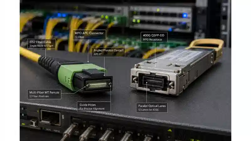
An eight-lane parallel module may use two MPO-12 connectors or one MPO-16 connector. Dual MPO-12 can divide the optics into two four-lane groups and can be convenient for 2×400G breakout. MPO-16 places the parallel lane set into one connector but requires dedicated 16-fiber adapters, trunks, and inspection equipment.
These ports are not interchangeable. Before ordering the cable, record the exact module connector and confirm whether the optical port is pinned or unpinned. For lower-speed endpoints, an appropriate MPO harness cable may be required rather than a straight trunk.
APC, UPC, Pinning, and Polarity
"MPO cable" is not a complete specification. Record all of the following:
- MPO-12 or MPO-16
- APC or UPC polish
- Male/pinned or female/unpinned interface
- Key orientation
- End-to-end polarity
- Breakout lane map
Some 800G module ports are pinned and require an unpinned mating cable. A physically insertable connector can still produce a failed or incorrectly mapped link. Review MPO polarity Methods A, B, and C before specifying trunks and patch cords.
For structured cabling, confirm that the selected MTP/MPO trunk cabling, adapters, cassettes, and harnesses preserve the transceiver's lane assignment from end to end.
800G Breakout Options and Failure Points
Depending on the module and platform, an 800G port may operate as:
- 1×800G
- 2×400G
- 4×200G
- 8×100G
Breakout is a system capability, not a promise created by the aggregate module rate. The switch ASIC, network operating system, module application, CMIS data-path selection, optical mapping, remote transceivers, and FEC configuration must support the same mode.
| Symptom | Likely Check | Why It Matters |
|---|---|---|
| Module is recognized but no link appears | Host application and port mode | Inventory access does not activate the correct data path |
| Only some breakout legs work | Lane map, harness polarity, and remote-port settings | One group may be mapped or configured differently |
| Optical power is present but errors rise | FEC, cleanliness, channel loss, and temperature | Received light alone does not prove adequate margin |
| Module works after insertion but fails after reboot | Firmware, application selection, and saved port configuration | The host may not restore the same module state |
| Third-party module is rejected | Platform coding policy and software release | Mechanical and optical compatibility do not override host policy |
800G OSFP vs QSFP-DD
Both OSFP and QSFP-DD can provide eight high-speed host lanes, but they are different mechanical systems. FOCC's QSFP form-factor guide provides background on the QSFP family.
| Factor | OSFP | QSFP-DD |
|---|---|---|
| Mechanical envelope | Larger module body | More compact QSFP-family body |
| Thermal approach | Substantial thermal headroom with several top and heatsink formats | High-density design with host thermal provisions |
| Legacy form-factor compatibility | Not designed primarily around classic QSFP insertion | MSA maintains backward compatibility with classic QSFP-family modules |
| Optical reach | Determined by VR8, DR8, FR4, or another optical interface | Also determined by the optical interface, not the form factor |
| Selection rule | Use when required and supported by the host | Use when required and supported by the host |
The QSFP-DD MSA hardware specification states that the module and cage family remains backward compatible with the classic QSFP form factor. That advantage does not make QSFP-DD electrically or mechanically interchangeable with OSFP.
Practical rule: select the form factor specified by the switch or adapter. Then select the optical interface, reach, connector, and breakout mode within that supported form factor.
Power and Thermal Planning
800G optics generally require more thermal attention than earlier client transceivers, but power varies by optical architecture and vendor. The OSFP MSA defines thermal classes extending to approximately 33 W in the current specification; this is a design envelope, not the expected consumption of every shipping module.
Check the module's typical and maximum power, the host's per-port limit, the chassis optical power budget, fan mode, airflow direction, ambient limit, and any restrictions on adjacent populated ports. FOCC's article on how optical transceiver modules manage high-temperature conditions provides related thermal context.
Integrated Heatsink vs OSFP-RHS
A standard OSFP module may include an integrated heatsink or a top surface designed for a particular host cage. An OSFP-RHS module relies on a riding heatsink installed in the host cage. The module and cage operate as one thermal system, so a standard, flat-top, finned-top, and RHS format should not be treated as automatically interchangeable.
NVIDIA's official 800G XDR OSFP-RHS documentation provides a current example: the module uses four 200G PAM4 channels and relies on a riding-heatsink format for the designated ConnectX-8 and Quantum-X800 environment.
Where 800G OSFP Is Deployed
AI and HPC Back-End Networks
AI training fabrics move large volumes of data among accelerators, network adapters, storage systems, leaf switches, and spine switches. OSFP's bandwidth and thermal capacity make it relevant to these environments, but Ethernet and InfiniBand modules may use different port modes, lane architectures, and approved cable sets.
Spine-Leaf Data Center Fabrics
An 800G spine port may serve one 800G peer or several lower-speed links through breakout. The correct optical type depends on rack layout, channel length, fiber availability, and the target leaf-port speeds. These choices should be coordinated with the broader data center design and architecture, rather than made as a transceiver-only decision.
Data Center Interconnect
For campus or metro links, a short-reach DR8 or VR8 client optic may not be appropriate. Longer links can require duplex client optics, a coherent pluggable, a transponder, wavelength planning, or line-system compatibility. FOCC's introduction to data center interconnect provides a starting point for that wider design problem.
How to Choose an 800G OSFP Module
- Identify the exact host. Record the switch, router, or adapter model, network operating system, software release, and port location.
- Confirm the OSFP thermal format. Determine whether the port accepts a standard integrated-heatsink module, flat-top design, finned-top design, or OSFP-RHS.
- Define the protocol and port mode. Specify 800GbE, InfiniBand, 1×800G, 2×400G, 4×200G, 8×100G, or another supported application.
- Measure the complete channel. Include trunks, patch cords, cassettes, adapters, cross-connects, and routing allowance rather than using the straight-line rack distance.
- Select the optical architecture. Compare VR8, DR8, and 2×FR4 based on distance, fiber count, installed infrastructure, breakout, and maintenance needs.
- Specify the complete connector. Include MPO-12 or MPO-16, APC or UPC, pinning, key orientation, polarity, and remote-end connector.
- Check host support. Confirm CMIS application, FEC, maximum module power, firmware, vendor coding, and documented breakout modes.
- Validate representative samples. Test recognition, link establishment, monitoring, traffic stability, temperature, error counters, breakout behavior, reboot recovery, and hot-plug recovery before volume deployment.
Compatibility Validation Before a Volume Purchase
| Test Item | Acceptable Result | A Failure May Indicate |
|---|---|---|
| Module recognition | Correct part, application, lane capability, and monitoring data appear | Coding, CMIS, firmware, or management communication issue |
| Port-mode selection | Required 800G or breakout application can be selected and retained | Unsupported host software or module application |
| FEC status | Expected FEC mode is active at both ends | Host or remote-end mismatch |
| Optical monitoring | Tx/Rx values are within the vendor's specified limits | Loss, contamination, lane mapping, or incompatible optics |
| Temperature and voltage | Readings remain within specified operating limits under traffic | Airflow, power, cage, or thermal-format problem |
| Error counters | Counters remain stable within the platform's acceptance criteria | Insufficient optical or electrical margin |
| Breakout traffic | Every lower-speed leg passes traffic independently | Lane map, cable polarity, FEC, or remote-port mismatch |
| Reboot and hot-plug recovery | The same application and stable link return without manual repair | Initialization, firmware, or saved-configuration issue |
A pass criterion must come from the selected module and host documentation. Avoid inventing a universal optical-power or temperature threshold, because those limits vary by product.
From OSFP800 to 1.6T: What Changes Next?
The OSFP form factor was designed with electrical and thermal headroom beyond one generation. The next step is not simply a faster label. Moving toward 1.6T involves host lanes operating at up to 200G per lane, tighter electrical-channel requirements, more demanding DSP and FEC implementation, and increased attention to module power and system cooling.
The transition is already visible in platform-specific 800G products that use four 200G channels rather than eight 100G channels. This does not make every 800G module a direct bridge to 1.6T, but it shows why lane architecture, connector format, and host generation must be recorded in addition to aggregate data rate.
Common Selection Mistakes
| Mistake | Better Approach |
|---|---|
| Buying by "800G OSFP" label alone | Specify protocol, lane architecture, reach, connector, thermal format, and host |
| Treating OSFP as an optical reach standard | Select VR8, DR8, 2×FR4, or another defined optical interface separately |
| Ordering an unspecified "MPO cable" | Record fiber count, polish, pinning, polarity, and lane map |
| Assuming all breakout modes are available | Check the exact module application and switch software support |
| Ignoring airflow and heatsink format | Validate module power, cage design, fan mode, and ambient limits together |
| Approving a module after an idle link test | Test traffic, FEC, counters, temperature, breakout, reboot, and hot-plug recovery |
FAQ
Q: Is OSFP the same as OSFP800?
A: OSFP is the broader form-factor family. OSFP800 commonly describes an implementation with eight 100G electrical host lanes, but product naming and supported applications must be checked against the relevant MSA revision and vendor data sheet.
Q: Does every 800G OSFP module use eight 100G lanes?
A: No. Eight 100G lanes are common in OSFP800 Ethernet designs, while some newer platform-specific 800G modules use four 200G channels.
Q: Can an 800G OSFP work in a 400G OSFP port?
A: Physical insertion is not enough. The host must support the module's electrical lane rate, power, CMIS application, firmware, cooling, and operating mode. Reduced-speed operation is platform-specific.
Q: Does every 800G OSFP support 2×400G breakout?
A: No. The module, host ASIC, operating system, FEC configuration, cable map, and remote endpoints must all support the same 2×400G application.
Q: Should I choose MPO-16 or dual MPO-12?
A: Choose the connector documented for the module and host. Dual MPO-12 can align with two optical groups and existing MPO-12 infrastructure; MPO-16 provides one connector for the parallel lane set but requires compatible 16-fiber cabling and test equipment.
Q: Can an 800G OSFP module use LC connectors?
A: Yes. Wavelength-multiplexed designs such as 2×FR4 can use two duplex LC interfaces. Parallel VR8 and DR8 implementations commonly use MPO interfaces.
Q: Does CMIS compliance guarantee switch compatibility?
A: No. CMIS standardizes management and application selection, but the host must still support the module's application, power, coding, firmware, port mode, and FEC behavior.
Conclusion
An 800G OSFP module should be selected as part of a complete host-and-cabling system. Start with the exact switch or adapter, then confirm the protocol, lane mode, optical reach, connector, polarity, breakout, CMIS application, FEC, power, and thermal format.
Before requesting a quotation, prepare the host model, software version, target port mode, link distance, fiber type, connector format, breakout requirement, remote endpoint, airflow direction, and module-top requirement. To discuss a compatible optical and cabling configuration, send these details through the FOCC inquiry form.