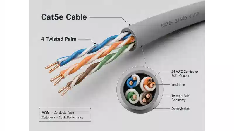
Cat5 wire gauge is commonly described as 24 AWG, especially when people are referring to standard Cat5e permanent cable. That answer is useful as a starting point, but it is not a complete cable specification.
American Wire Gauge describes the nominal size of an individual conductor. Category 5 or Category 5e describes the transmission performance of the complete balanced twisted-pair cable and its connecting hardware. A cable can contain 24 AWG conductors and still fail Cat5e performance because of poor pair geometry, unsuitable materials, inconsistent twisting, excessive resistance, damaged insulation, or bad termination.
This guide explains what gauge is commonly used in Cat5 and Cat5e cable, how conductor size affects resistance, insertion loss, Power over Ethernet, flexibility, and connector fit, and how to decide whether an existing cable should be reused or replaced. For current products and construction options, review the FOCC network cable range.

Quick Answer: What Gauge Is Cat5 Cable?
Conventional Cat5 and Cat5e permanent cable commonly uses four pairs of 24 AWG solid copper conductors. Flexible equipment cords may use stranded conductors, and specialty high-flex, industrial, slim, or power-focused products may use a different documented gauge.
| Application | Common Starting Point | Why |
|---|---|---|
| Permanent Cat5e horizontal link | 24 AWG solid copper | Stable electrical performance and reliable IDC termination |
| Short Cat5e equipment cord | Product-specific stranded copper | Flexibility at the equipment or patching area |
| High-flex industrial route | Qualified stranded construction | Repeated motion and environmental durability |
| PoE-powered device route | Low-resistance, standards-compliant copper cable | Voltage-drop and temperature control |
| Existing legacy Cat5 link | Identify and test the installed cable | The label and gauge alone do not prove application support |
A current product should be evaluated from its complete data sheet rather than from a generic gauge assumption. FOCC's Cat5e UTP cable page is one place to begin reviewing construction and jacket options, but the ordered specification and acceptance evidence should control the final decision.
Category defines transmission performance. AWG defines conductor size.
Cat5 or Cat5e? Clarify the Name Before Comparing Gauge
"Cat5" is still used casually for older four-pair Ethernet cable, patch cords, and even modern Cat5e products. That shorthand can create errors in maintenance records and purchase orders.
Original Category 5 and Category 5e belong to the same general balanced twisted-pair family, but Cat5e introduced tighter electrical requirements for applications that use all four pairs. In practical new procurement, the relevant baseline is usually Cat5e rather than original Category 5. Original Cat5 is mainly a legacy-cabling question: what is installed, what was it designed to support, and can its present condition be verified?
When the broader cable construction is unfamiliar, FOCC's guide to understanding data network cables provides additional context. For an RFQ, avoid requesting only "Cat5 cable." State the required Category, conductor construction, material, shielding, jacket, application, test configuration, and documentation.
What AWG Means for Cat5 and Cat5e Cable
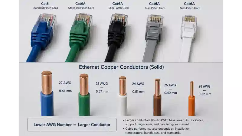
AWG stands for American Wire Gauge. It uses an inverse numbering system: a lower AWG number means a larger conductor, while a higher number means a smaller conductor. A 23 AWG conductor is therefore larger than 24 AWG, and 26 AWG is smaller.
The ASTM B258 specification defines standard nominal diameters and cross-sectional areas for solid round AWG conductors. Approximate nominal solid-conductor diameters are shown below.
| AWG | Approximate Solid-Conductor Diameter | Relative Size |
|---|---|---|
| 22 AWG | 0.64 mm | Larger |
| 23 AWG | 0.57 mm | Larger than 24 AWG |
| 24 AWG | 0.51 mm | Common in Cat5e permanent cable |
| 26 AWG | 0.40 mm | Smaller and more flexible |
| 28 AWG | 0.32 mm | Used in some slim patch-cord designs |
These dimensions describe the metal conductor, not the insulated wire or finished cable. Insulation thickness, pair lay, separators, shields, drain wires, and jacket construction can make two cables with the same AWG very different in outside diameter and connector fit.
FOCC's AWG UTP and FTP LAN cable page illustrates why gauge must be reviewed together with Category and shielding rather than as an isolated product name.
Does Category 5 Require One Wire Gauge?
No single AWG value proves that a cable meets a Category. A balanced twisted-pair cable must control a wider set of electrical and mechanical properties, including characteristic impedance, insertion loss, return loss, crosstalk, propagation delay, delay skew, DC resistance, resistance unbalance, pair balance, and environmental durability.
A well-designed 24 AWG Cat5e cable can outperform a poorly made cable with a larger conductor. A thicker conductor does not repair inconsistent pair twisting, excessive untwist at the connector, damaged insulation, poor balance, or an unsuitable plug.
This distinction prevents two common purchasing errors:
- Accepting any 24 AWG cable as Cat5e.
- Assuming a 23 or 22 AWG cable is automatically Cat6, Cat6A, or suitable for a longer unsupported Ethernet channel.
The required Category should be established by the manufacturer's controlled specification and verified with the appropriate component, permanent-link, or channel test.
Solid, Stranded, and Conductor Material

Solid Copper for Permanent Links
A solid conductor consists of one continuous metal wire beneath the insulation. It holds its shape and seats reliably in insulation displacement contacts used in keystone jacks, patch panels, and connecting blocks.
Fluke Networks' guidance on solid and stranded wire cable explains that solid cable is the normal construction for permanent horizontal links, while stranded construction is used mainly where flexibility is required.
Stranded Copper for Flexible Cords
A stranded conductor is made from several smaller wires. It tolerates repeated movement better than a solid conductor and is therefore useful for equipment cords, work-area cords, and cross-connects.
The trade-off is higher resistance and attenuation for comparable gauge and length. This does not make stranded cable defective; it means the channel design must account for its intended location, length, temperature, and PoE load. A flexible patch cord should not be substituted for permanent horizontal cable merely because the jacket is marked Cat5e.
Bare Copper, Tinned Copper, and CCA
AWG describes geometry, not conductor material. The same gauge marking can appear on bare copper, tinned copper, copper-clad aluminum, or a specialty alloy.
Copper-clad aluminum has different electrical behavior from solid copper. Fluke Networks' CCA cable application note shows why DC resistance and resistance unbalance are important when evaluating suspect material, particularly for PoE.
For structured cabling, the purchase specification should state the conductor material explicitly and require supporting documentation. FOCC also discusses copper terminology in its copper conductor comparison. Visual color, weight, or a simple scrape test may provide clues, but none should replace traceable material information and electrical testing.
How Wire Gauge Affects Network Performance

DC Resistance and Voltage Drop
For conductors made from the same material, a larger cross-sectional area normally produces lower resistance. Higher resistance increases voltage drop and converts more delivered power into heat.
Three related terms should not be confused:
- Conductor resistance describes one conductor under defined conditions.
- DC loop resistance covers the round-trip path through two conductors.
- Resistance unbalance describes unequal resistance within or between powered pairs.
For PoE, low average resistance is not enough if current does not divide evenly. Fluke Networks' explanation of DC resistance unbalance shows why pair-to-pair and conductor-to-conductor differences can matter.
Insertion Loss and Usable Margin
Insertion loss is the reduction in signal strength through the cabling channel. Gauge contributes to it, but so do frequency, conductor construction, cable length, temperature, patch cords, connectors, pair geometry, and installation damage.
Smaller conductors generally offer less electrical margin than larger conductors of comparable construction. The correct conclusion is not that one AWG "sets the speed." The installed channel must pass the test limit for the required Category or application.
Power over Ethernet and Temperature
Power over Ethernet sends power and data over balanced pairs. IEEE 802.3bt expanded standardized power delivery by using all four pairs in the structured wiring plant.
Cable heating depends on resistance, current balance, length, bundle size, ambient temperature, jacket material, and connector quality. A 24 AWG Cat5e cable may support an approved PoE application, but AWG alone is not a PoE qualification. The cable, channel, environment, PSE, and powered device must be evaluated together.
For installation-level considerations, see FOCC's guide to lowering cabling temperature for PoE.
Flexibility and Cable Density
Smaller or stranded conductors can reduce patch-cord diameter and improve flexibility in dense racks. The benefit comes with additional resistance and insertion loss, so the total flexible-cord length and channel design must be controlled.
Electromagnetic Interference
A larger conductor does not make a cable immune to electromagnetic interference. Noise performance depends more directly on pair balance, twist consistency, shielding, grounding, separation, and termination workmanship. Gauge can influence available loss margin, but it cannot replace correct balanced-pair design.
How to Read a Cat5e Cable Data Sheet
A useful data sheet should allow a buyer to connect the product construction to the intended application. Do not stop at the Category and AWG fields.
| Field | What to Check | Why It Matters |
|---|---|---|
| Category and frequency range | Declared product performance and test basis | Gauge alone does not establish transmission performance |
| Conductor | AWG, solid or stranded, material, plating | Affects resistance, flexibility, and termination |
| Pair construction | Pair count, insulation, pair lay, separator | Affects balance and crosstalk |
| DC resistance | Maximum value and whether it is conductor or loop resistance | Important for voltage drop and PoE |
| Resistance unbalance | Declared limit or supported test requirement | Important for current sharing |
| Insertion loss and crosstalk | Performance by frequency | Shows whether the cable meets its Category target |
| Outside and insulation diameter | Actual dimensional range | Controls pathway fill and connector compatibility |
| Jacket and temperature | PVC, LSZH, CMR, CMP, outdoor or industrial rating | Must suit the installation environment |
| Shielding | U/UTP, F/UTP, S/FTP or another construction | Controls grounding and termination requirements |
| Approvals and traceability | Listing, product code, batch identity, revision | Supports procurement and repeat-order control |
Jacket terminology is a separate design decision from gauge. For example, FOCC's guide to CMP cable and plenum ratings explains why the installation space and applicable code must be considered independently of conductor size.
How to Identify an Existing Cat5 or Cat5e Cable
Before reusing an installed link, record the jacket marking rather than relying on appearance or an informal description.
Example marking: CAT5E 4PR 24AWG SOLID BC U/UTP CMR
| Marking | Typical Meaning |
|---|---|
| CAT5E | Declared Category 5e performance |
| 4PR | Four twisted pairs |
| 24AWG | Nominal conductor gauge |
| SOLID | Solid-conductor construction |
| BC | Bare copper, subject to manufacturer documentation |
| U/UTP | Unshielded overall cable with unshielded pairs |
| CMR | Riser-rated jacket designation |
Also capture the manufacturer, product number, listing mark, batch or lot code, sequential length marking, temperature range, shielding, and jacket rating. A cable marked only "24 AWG" does not provide enough information to approve it as Cat5e.
Can Existing Cat5 Wiring Be Reused?
Reuse should be based on the required application and measured evidence, not on link lights or conductor gauge.
Identify the cable. Record the complete jacket marking, conductor construction, route, connectors, and any undocumented joints.
Define the application. State the required Ethernet speed, PoE type, device load, environmental conditions, and service life.
Inspect the route. Look for crushed cable, tight bends, damaged jackets, excessive pair untwist, poor punch-downs, mixed components, and uncontrolled splices.
Select the correct test level. Wire-map testing is useful for basic faults, but it does not certify Category performance.
Review PoE risk. Consider loop resistance, resistance unbalance, length, bundle size, ambient temperature, and connector condition.
Decide and document. Retain the link only when the evidence supports the required application with suitable margin.
Illustrative Audit Scenario
An installed cable is marked Cat5e, 24 AWG, solid, and U/UTP. The route appears undamaged, but the work-area outlet has been reterminated several times and the project now requires PoE cameras.
The gauge and Category marking are not enough for approval. The review should confirm conductor material, examine the terminations, test the appropriate link configuration, check resistance and resistance unbalance where required, and compare the result with the camera and PSE requirements. If the link passes the approved test and the PoE design remains within its environmental limits, reuse may be reasonable. If documentation is missing, the cable fails certification, or power delivery is unstable, replacement or redesign is the safer decision.
This is an illustrative method, not a report of a completed FOCC project.

Connector and Termination Compatibility
RJ45 plugs, field plugs, keystone jacks, and patch panels accept defined conductor and insulation ranges. A plug that physically fits the cable may still be electrically or mechanically unsuitable.
Check all of the following:
- Supported AWG range
- Solid or stranded compatibility
- Conductor insulation diameter
- Finished cable outside diameter
- Shielded or unshielded construction
- Contact design for the conductor construction
- IDC range for jacks and patch panels
- Strain-relief and boot fit
The conductor gauge can match while the insulation diameter does not. FOCC's guide to choosing an RJ45 plug and boot provides additional termination context.
When Should Cat5e Be Upgraded to Cat6 or Cat6A?
Gauge should not be the only reason to upgrade. The decision should follow the complete application, route, lifecycle, and test evidence.
| Condition | Cat5e May Remain Suitable When | Consider Cat6 or Cat6A When |
|---|---|---|
| Existing installation | The link is documented, passes the required test, and has sufficient margin | The Category is unknown, certification fails, or remediation is extensive |
| New commercial build | The application and lifecycle are limited and explicitly approved | Higher future bandwidth, dense PoE, or long service life is expected |
| PoE | Resistance, unbalance, temperature, and bundle conditions are controlled | High sustained power or difficult thermal conditions reduce margin |
| Pathway capacity | Existing conduit cannot accept a larger cable and the application is verified | Pathways can support a more future-ready cable |
| Maintenance | Replacement components match the accepted installed system | Mixed components and repeated faults make the old system difficult to control |
FOCC's Cat5 vs Cat5e vs Cat6 guide covers the immediate comparison, while the overview of Ethernet categories from Cat5 to Cat8 provides broader context. The article on whether you can use Cat6 cable on a Cat5 network is relevant when replacing only part of an existing channel.
Testing Existing Cat5 and Cat5e Cabling
Testing should match the decision being made. Fluke Networks distinguishes verification, qualification, and certification as different levels of evidence.
| Test Level | What It Helps Establish | What It Does Not Prove Alone |
|---|---|---|
| Wire-map verification | Opens, shorts, reversals, crossed pairs, and split pairs | Category compliance or full application margin |
| Qualification | Whether an existing link is likely to support selected network applications | Full standards certification |
| Permanent-link certification | The fixed horizontal cable and connecting hardware | Performance of the final patch cords |
| Channel certification | The complete end-to-end cabling channel | Switch configuration or application software |
| PoE-related measurements | Resistance, unbalance, and selected power-delivery conditions | Every possible bundle and ambient-temperature condition |
FOCC's guide to testing an Ethernet cable can support basic inspection and tester setup. For acceptance, the record should identify the cable, link, selected limit, tester, calibration status, measured result, date, operator, and electronic report file.
Permanent Link vs Channel
A permanent-link test focuses on the installed fixed cabling and its connecting hardware. A channel test includes the cords used to connect equipment at both ends. Use the configuration specified by the project; a passing channel result should not be presented as a permanent-link result, or vice versa.
Common Failure Symptoms and What to Check
| Observed Symptom | Possible Cabling Factors | Next Check |
|---|---|---|
| Link negotiates below the expected speed | Pair fault, excessive loss, poor termination, damaged cable, unsupported channel | Check all four pairs and run the appropriate qualification or certification test |
| PoE device repeatedly restarts | Voltage drop, high resistance, resistance unbalance, damaged connector, PSE or device issue | Measure the cabling and review the complete power path |
| Connection fails when the cable is moved | Broken stranded conductor, poor crimp, damaged latch, loose IDC termination | Inspect both ends and perform movement-aware troubleshooting |
| One batch of plugs terminates poorly | AWG or insulation diameter outside the plug range | Compare the plug specification with the actual conductor and cable dimensions |
| Performance degrades in a hot bundle | Temperature-related insertion loss, high resistance, dense loading | Review bundle, ambient conditions, PoE load, and channel margin |
| CCA is suspected | Unexpected resistance or unbalance, uncertain documentation | Quarantine the cable and use traceable material information plus electrical testing |
These symptoms are starting points, not universal root causes. Active equipment, configuration, and the powered device must be investigated alongside the cabling.
Common Cat5 Wire-Gauge Mistakes
- Assuming every Cat5 or Cat5e cable is exactly 24 AWG. Read the controlled data sheet and jacket marking.
- Treating 24 AWG as proof of Cat5e. Require Category evidence and the appropriate test.
- Using stranded cable as a permanent horizontal substitute. Match construction to the link design.
- Assuming thicker wire extends Ethernet without limit. Follow the approved application and channel specification.
- Ignoring conductor material. Specify copper construction and supporting evidence.
- Using any RJ45 plug that fits. Match conductor, insulation, shielding, and outside diameter.
- Approving an old link because the switch shows link-up. Link status does not establish margin or PoE suitability.
- Attributing EMI performance to gauge alone. Review balance, twisting, shielding, grounding, and installation.
FAQ
Q: What gauge wire is normally used in Cat5 cable?
A: Conventional Cat5 and Cat5e permanent cable commonly uses 24 AWG solid copper conductors. Patch cords and specialty products may use another documented construction.
Q: Is Cat5e always 24 AWG?
A: No. Twenty-four AWG is common, but it is not the definition of Cat5e. The complete product must meet its declared Category performance.
Q: Is 23 AWG better than 24 AWG?
A: A same-material 23 AWG conductor is larger and normally has lower resistance than 24 AWG. It is also less flexible and may require different connecting hardware. It does not automatically provide a higher Category.
Q: Can 26 AWG Cat5e support Ethernet?
A: It can be used in a qualified Cat5e product, often where flexibility is required. Follow the product's channel, temperature, PoE, and connector limitations.
Q: Does wire gauge determine Ethernet speed?
A: No. Gauge affects resistance and insertion-loss margin, while supported speed depends on the complete cable design, length, connecting hardware, installation, and test result.
Q: Can old Cat5 wiring support Gigabit Ethernet?
A: The gauge and appearance cannot answer that question. Identify all four pairs, inspect the route and terminations, and qualify or certify the installed link for the required application.
Q: Can 24 AWG Cat5e support PoE?
A: It may support approved PoE applications when the complete cable and channel meet the required resistance, unbalance, temperature, length, and installation conditions.
Q: When should Cat5e be replaced?
A: Replace or redesign when the Category cannot be verified, the link fails the required test, PoE margin is inadequate, the route is damaged, components are incompatible, or the expected service life justifies a higher Category.
Cat5 and Cat5e Procurement Checklist
- Exact Category and intended application
- AWG and conductor construction
- Conductor material and supporting documentation
- Permanent cable or patch-cord use
- Shielding and grounding requirements
- Jacket, temperature, and installation rating
- PoE type, load, bundle, and environmental conditions
- Connector AWG, insulation, and outside-diameter range
- Required permanent-link or channel configuration
- Qualification or certification evidence
- Product identity, batch traceability, and change control
For broader category selection, review FOCC's guide to choosing the right Ethernet cable category.
Make the Decision From the Complete Cable System
Cat5 wire gauge matters because conductor size affects resistance, voltage drop, insertion-loss margin, PoE behavior, flexibility, and termination compatibility. It is never the complete specification.
For a new purchase, state the Category, AWG, construction, material, shielding, jacket, connectors, application, test configuration, and required records. For an existing installation, identify the cable, inspect the route, select the correct test, review PoE conditions, and document the reuse or replacement decision.
When the project requirements are defined, you can send the required cable specification for product and configuration review.