An "800G MPO loopback" is not a complete specification. Two 800G transceivers can operate at the same Ethernet rate while presenting different optical interfaces: one may use a single MPO-16, another may use two MPO-12 connectors, and another may use duplex optics instead of MPO.
For loopback testing, the connector architecture has to match the actual transceiver. Fiber type, APC or UPC polish, MPO gender, active fiber positions, Tx-to-Rx routing and returned optical power can all affect whether the test works.
If you need broader background on the speed itself, FOCC also has an overview of 800G Ethernet. This guide stays focused on a narrower engineering question: when should an 800G test use MPO-16, and when does it require dual MPO-12?

MPO-16 vs Dual MPO-12 at a Glance
| Parameter | MPO-16 Loopback | Dual MPO-12 Loopback |
|---|---|---|
| Optical connectors | One MPO-16 | Two MPO-12 connectors |
| Typical 800G parallel-lane grouping | Eight Tx/Rx pairs in one interface | Two groups, commonly four Tx/Rx pairs per MPO |
| Typical active fibers | 16 active fibers | Typically 8 active fibers per MPO interface |
| Internal return routing | One 16-fiber Tx-to-Rx mapping | Two separate lane-group mappings |
| Fiber mode | SMF or MMF, depending on the transceiver | SMF or MMF, depending on the transceiver |
| Polish | Must match the transceiver | Must match the transceiver |
| Interchangeable? | No | No |
The practical rule is straightforward: select the loopback from the exact optical interface, not from the 800G label.
Why 800G Does Not Define the Loopback Connector
800G describes aggregate Ethernet capacity. It does not, by itself, define how optical lanes are presented at the front of a transceiver.
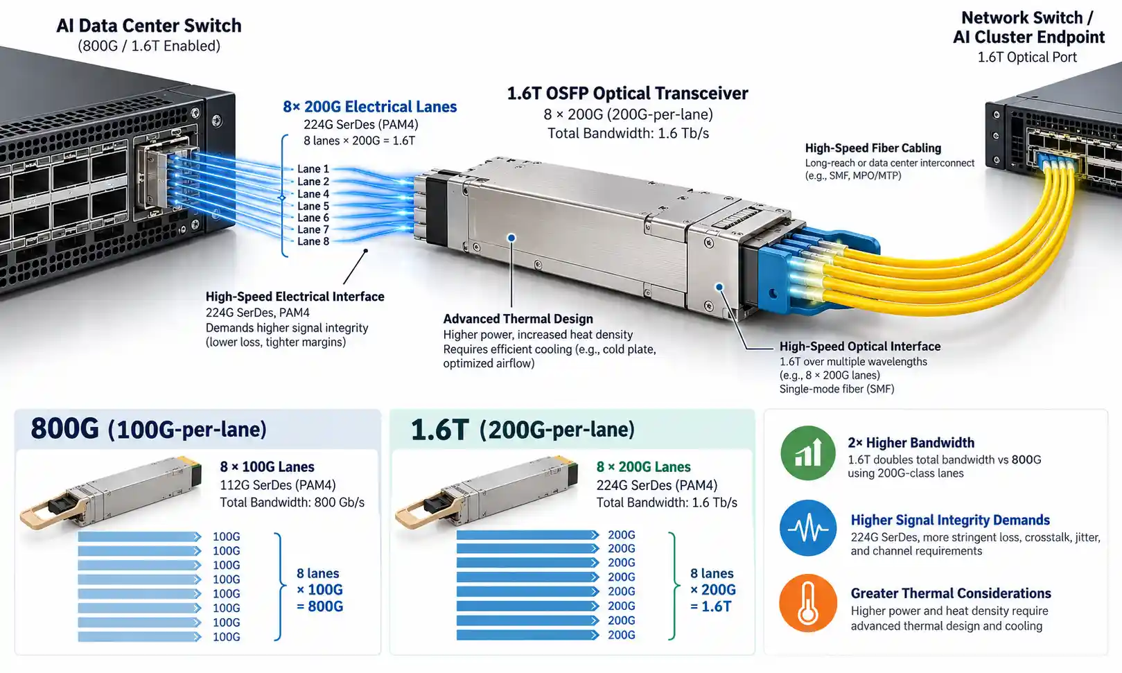
In an eight-lane parallel implementation, eight transmit lanes and eight receive lanes can be presented through one MPO-16 connector. In another design, the same aggregate 800G capacity can be divided into two optical groups and presented through two MPO-12 connectors. Some 800G modules use wavelength-division multiplexing and duplex connectors instead.
This is visible in current manufacturer portfolios. Cisco lists OSFP-800G-DR8 with dual MPO-12 APC and OSFP-800G-DR8P with MPO-16 APC. Arista likewise lists 800G modules with 2×MPO-12 APC, MPO-16 APC and duplex interfaces. The exact part number therefore matters more than a generic description such as "800G OSFP."
What Is an MPO-16 Loopback for 800G Testing?
An MPO-16 loopback is a passive multi-fiber assembly that returns transmit lanes from an MPO-16 optical interface to the receive lanes expected by the same transceiver or test port. It contains no signal regeneration or protocol logic; its function is optical routing.
For the common 100 Gb/s-per-lane 800G parallel architecture discussed here, the interface uses eight transmitting fibers and eight receiving fibers. Fluke Networks describes this 16-fiber arrangement as eight Tx and eight Rx fibers operating at 100 Gb/s per lane.
Examples include Cisco OSFP-800G-DR8P and Arista OSFP-800G-XDR8, both of which use MPO-16 APC with single-mode fiber. Arista also lists MPO-16 APC multimode examples such as OSFP-800G-VSR8.
For the physical assembly format, see FOCC's MTP/MPO fiber loopback module.

What Is a Dual MPO-12 Loopback Configuration?
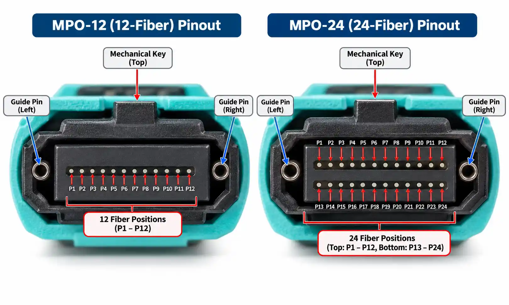
A dual MPO-12 800G interface presents the optical lanes through two separate MPO-12 connectors. In commonly used 800G designs, each MPO carries one group of four Tx and four Rx lanes, so not every position in the 12-fiber ferrule is necessarily active.
Cisco OSFP-800G-DR8 is one example: the module uses dual MPO-12 APC interfaces and eight pairs of single-mode fiber distributed across the two connectors. Arista lists a similar two-connector structure for products such as OSFP-800G-2XDR4, QDD-800G-2XDR4, OSFP-800G-2PLR4 and OSFP-800G-2VSR4.
A dual MPO-12 loopback must preserve those two optical groups. Treating the design as "a 16-fiber loopback with a different connector shell" can produce the wrong lane routing even when the total number of active fibers appears similar.

Mapping: What Is Universal and What Is Module-Specific?
Connector type alone does not determine a working loopback. A parallel transceiver does not merely need light returned somewhere on the receive side; each transmit path has to be returned to the receive position expected by the test configuration.
| Mapping Question | MPO-16 | Dual MPO-12 |
|---|---|---|
| How many optical groups? | One | Two |
| Typical lane organization in the 800G examples discussed here | 8 Tx + 8 Rx | 4 Tx + 4 Rx per MPO |
| Can fiber count alone define the loopback? | No | No |
| What must be verified? | Active positions and the required Tx-to-Rx return pairs | Which lanes belong to each MPO plus the Tx-to-Rx return pairs inside each group |
A universal fiber-position table would be misleading unless it is tied to a specific transceiver interface and verified lane map. Manufacturer documents may identify the connector, lane count and breakout capability without publishing the exact custom loopback pairing needed for every test setup.
For a custom assembly, confirm the port's active positions and required return pairs from the transceiver vendor, platform documentation or a verified interface drawing. Also keep general MPO polarity methods separate from the loopback's internal Tx-to-Rx mapping: a cabling polarity method does not, by itself, define a custom loopback map.
How to Specify the Correct 800G Loopback
1. Start With the Exact Transceiver Part Number
Use the manufacturer's full part number whenever possible. "800G," "OSFP" and even "800G DR8" can still be insufficient because multiple physical implementations can exist under the same broad speed or optical family.
2. Confirm the Optical Interface
Check whether the module uses MPO-16, 2×MPO-12, duplex LC or another interface. If the module is duplex-based, an MPO loopback is not the correct physical solution.
3. Match the Fiber Type
Single-mode and multimode assemblies are not interchangeable simply because the connector fits. DR-class parallel optics are commonly single-mode, while short-reach VSR/VR implementations may be multimode. Use OM5 only when the transceiver manufacturer's specification explicitly supports it.
For more background before specifying the assembly, compare single-mode vs multimode fiber.
4. Match APC or UPC Polish
Many of the Cisco and Arista parallel 800G modules referenced in this article use APC MPO interfaces. That does not mean every MPO application is APC. The loopback ferrule polish has to match the optical port; APC and UPC end-face geometries should not be treated as interchangeable.
5. Confirm MPO Gender
A male MPO connector has guide pins, while a female connector has guide-pin holes. Cisco states that the MPO ports on the cited 800G OSFP modules are male/pinned, so the mating cable or loopback connector must be female/unpinned.
If the terminology is unfamiliar, see the FOCC guide to MTP/MPO male vs female connectors.
6. Verify Tx/Rx Mapping and Optical Power
Before manufacturing the loopback, verify the active fiber positions, Tx-to-Rx return pairs and the expected optical loss. These are engineering inputs, not details that should be inferred from connector count.
Does an 800G MPO Loopback Need Attenuation?
Not automatically. A short loopback can have much lower loss than the network path for which a transceiver was designed, so the returned receive power should be checked against the module's optical specifications and the purpose of the test.
A useful simplified estimate is:
Estimated returned Rx power ≈ Tx output power − loopback insertion loss − added attenuation
This is a screening calculation, not a complete compliance model. Per-lane limits, measurement uncertainty, connector loss, receiver criteria and the specific test method still matter.
For example, Cisco publishes per-lane transmit and receive power ranges and maximum supported insertion loss for its 800G OSFP modules. That is the type of source that should be used before deciding whether an attenuated loopback is necessary. For a general explanation of the component itself, see what a fiber optic attenuator is.
Worked Specification Example: Cisco OSFP-800G-DR8P
This is a manufacturer-data example, not a claim about a specific customer test.
| Item | Specification to Start From |
|---|---|
| Transceiver | Cisco OSFP-800G-DR8P |
| Optical architecture | 800G parallel single-mode optics with eight fiber pairs |
| Optical connector | MPO-16 APC |
| Module MPO gender | Male / pinned |
| Mating loopback connector | Female / unpinned MPO-16 APC |
| Fiber | Single-mode fiber compatible with the module specification |
| Loopback mapping | Return the eight Tx lanes to the corresponding Rx lanes according to the verified module/test map |
| Attenuation | Determine from actual per-lane power, measured loopback loss, receiver limits and test objective |
The example shows why "800G MPO-16 loopback" is still incomplete as an RFQ. Gender, fiber, mapping and optical loss requirements remain part of the specification.
How an 800G Optical Loopback Test Works
A local test follows this path:
Switch or test platform → 800G transceiver → optical loopback → same transceiver receiver

- The transceiver sends optical signals on its Tx lanes.
- The loopback routes those lanes internally.
- The signals return through the designated Rx lanes.
- The host or test system evaluates link state, alarms, received power and other available diagnostics.
Because a remote transceiver is not required, this test is useful for isolating the local port, module and optical interface.
What a Loopback Test Can and Cannot Verify
| A Local Loopback Can Help Verify | It Does Not Fully Prove |
|---|---|
| Basic transmitter and receiver response | A long installed fiber route |
| Tx/Rx lane continuity | Remote-end equipment |
| Basic link establishment | Patch-panel and end-to-end insertion loss performance |
| Local port or module fault isolation | Long-duration BER performance |
| Production screening and burn-in workflows | Full interoperability or FEC margin across a production link |
If a local loopback passes but the deployed link still fails, the next diagnostic step may involve the installed fiber plant, the remote endpoint, optical power measurements, an OTDR or a BERT, depending on the symptom and test objective.
Why an 800G MPO Loopback Test Can Fail
| Symptom or Check | What to Verify |
|---|---|
| No link across all lanes | Connector architecture, gender, polish, mapping and returned optical power |
| One or more lanes missing | Lane map, contamination, damaged fibers and connector seating |
| Receiver alarms or unexpected diagnostics | Per-lane received power, mapping and module diagnostics |
| Intermittent behavior after reconnecting | MPO end-face cleanliness and physical mating condition |
| Local loopback passes but the installed link fails | Remote equipment, deployed fiber path, patching, loss budget and end-to-end test conditions |
Contamination deserves special attention with MPO interfaces because one ferrule carries multiple fibers. Inspect, clean and re-inspect before mating rather than repeatedly reconnecting a dirty end face.
MPO-16 vs Dual MPO-12 FAQ
Q: Can I use an MPO-16 loopback for every 800G transceiver?
A: No. Current 800G transceivers use multiple optical interface types, including MPO-16, dual MPO-12 and duplex designs. Match the exact module interface.
Q: Is MPO-16 always used for 800GBASE-DR8?
A: No. Cisco, for example, offers OSFP-800G-DR8 with dual MPO-12 APC and OSFP-800G-DR8P with MPO-16 APC.
Q: Does a dual MPO-12 800G loopback use all 12 positions in each connector?
A: Not necessarily. In the 800G examples discussed here, each MPO-12 commonly carries four Tx/Rx pairs, so some ferrule positions are not active. Verify the actual module lane arrangement.
Q: Can the same loopback be used for OSFP and QSFP-DD?
A: Possibly, but the form factor name does not determine optical compatibility. The connector, fiber type, polish, gender, active lanes, mapping and optical power requirements all need to match.
Q: Does every 800G loopback need added attenuation?
A: No. Determine attenuation from the actual optical power conditions and test objective, not from the Ethernet speed alone.
Conclusion
The choice between MPO-16 and dual MPO-12 for 800G loopback testing is an interface decision, not a speed-only decision. MPO-16 places the parallel lane set into one connector, while dual MPO-12 separates the lanes into two optical groups. They should not be substituted for one another.
Before ordering or manufacturing the loopback, verify the exact transceiver part number, optical connector, fiber type, polish, gender, active positions, Tx-to-Rx mapping and optical power requirements. That sequence removes the most common specification errors without relying on assumptions about "800G."