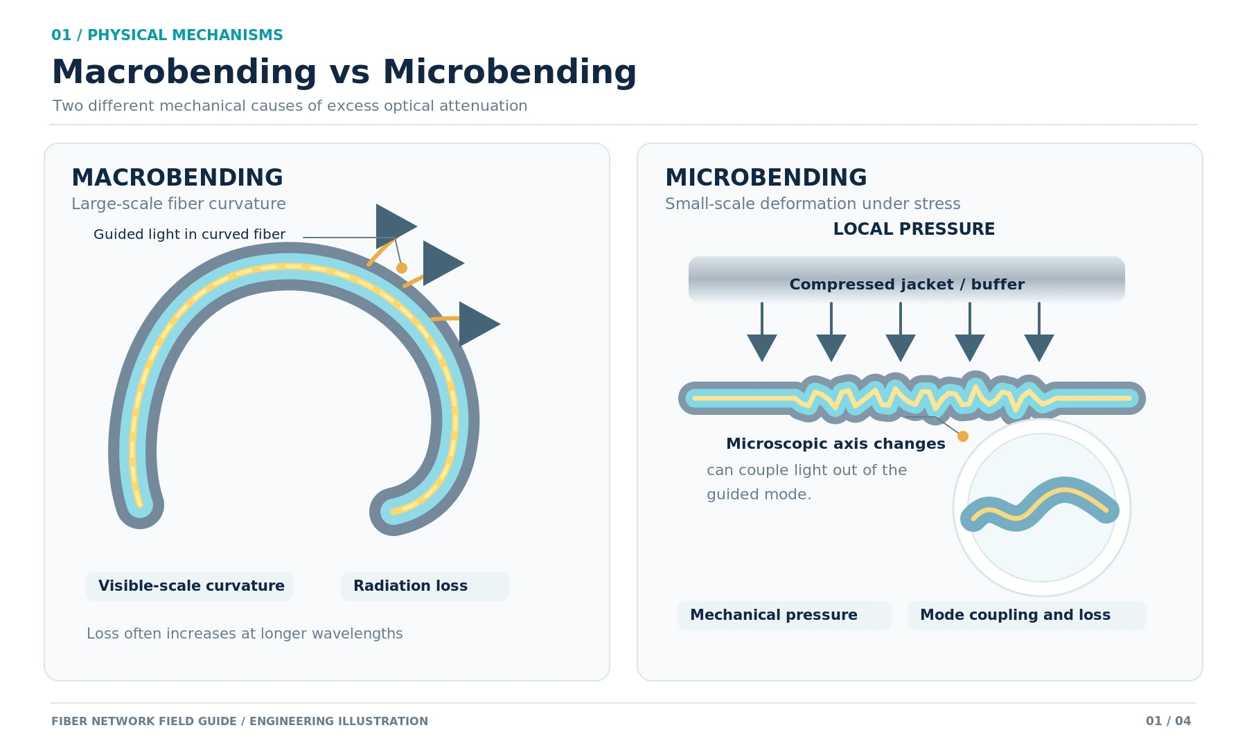
Fiber bend loss occurs when mechanical deformation allows some of the light guided through an optical fiber to escape or couple into lossy modes. Macrobending is associated with visible-scale curvature, such as a tight loop inside a patch panel. Microbending results from much smaller, stress-induced changes along the fiber, often caused by compression or cable construction. Both can increase attenuation, but they do not always produce the same test signature.
For an installed single-mode link, a localized OTDR event that becomes substantially more lossy at 1550 nm than at 1310 nm is a useful indication of possible macrobending. It is not proof by itself. The event location, test conditions, connector condition and physical cable route must agree before a technician can identify the cause and select a repair.
Macrobending vs Microbending: What Changes Inside the Fiber?
Light is guided by the fiber's refractive-index profile. In a tight macrobend, the guided field is disturbed enough for optical power to couple out of the guided mode. With microbending, small, often irregular deformations along the fiber axis can couple guided light into unwanted modes. The resulting loss depends on the fiber design, wavelength, mechanical stress and cable structure.
| Characteristic | Macrobending | Microbending |
|---|---|---|
| Physical cause | Visible-scale curvature of the fiber or cable | Microscopic deformation caused by localized or distributed stress |
| Typical locations | Patch panels, slack loops, splice trays, conduit entrances | Compressed cable sections, tight ties, buffer tubes, pressure points within the cable |
| Visual inspection | The tight route may be visible, although the fiber itself can be hidden | The fiber deformation is usually not visible through the cable structure |
| Possible OTDR finding | A localized, often nonreflective loss event with stronger loss at a longer wavelength | Additional attenuation across a section, sometimes without an isolated event |
| Confirmation | Match the trace distance to a physical bend; relieve the bend and retest | Examine the cable's mechanical condition and determine whether reducing stress changes the loss |
| Repair | Restore an acceptable route if the cable is undamaged | Remove the stress if reversible; replace damaged cable when necessary |
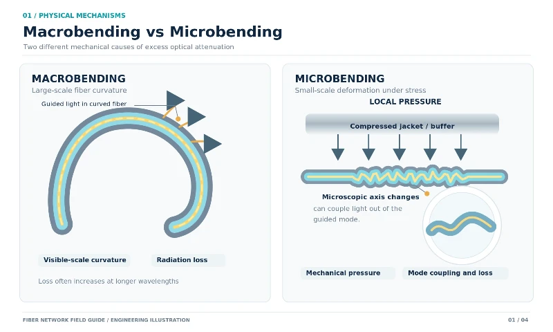
The Fiber Optic Association's explanation of macro- and microbending makes an important distinction: macrobending can be demonstrated with controlled bends, whereas microbending is strongly affected by coating and cable design and does not have one simple, reproducible field test.
Neither term is a substitute for the cable's permitted bend radius. The allowable limit during pulling may differ from the installed, unloaded limit, and the finished cable may have stricter requirements than the bare fiber. Those installation limits are addressed separately in minimum fiber bend radius specifications.
What Causes Bend-Induced Attenuation in Installed Links?
Patch Panels and Slack Storage
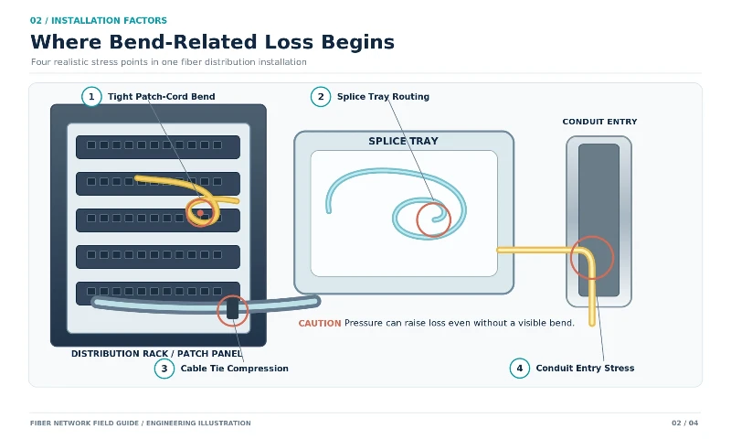
Excess slack forced into a small tray can create tight turns near adapters, splice protectors or cable exits. A jumper may also be pulled sharply across a panel edge after a port change. The route can remain intact and still introduce measurable loss. Inspect the complete path from the connector boot to the first supported cable run rather than looking only at the most obvious loop.
Cable Ties, Clamps and Compression
A tie tightened around the jacket can transfer pressure to the buffer or coated fiber. The resulting attenuation may not resemble a single sharp macrobend on an OTDR. Cable trapped beneath a rack bracket, squeezed at a cabinet door or compressed in an overfilled pathway can produce a similar problem. Loosening the support is a useful controlled check, but a visibly crushed jacket or deformed tube may require replacement.
Conduit Entries and Pulling Tension
A cable pulled around an undersized sheave or a sharp duct entry experiences bending and tensile load at the same time. These forces can damage internal elements even when the route appears acceptable after installation. Avoid inferring the permitted radius from cable diameter alone: the manufacturer's pulling-tension limit and bend requirements apply to the specific construction. General fiber optic cable installation guidelines provide the broader context for routing and pulling practices.
Temperature-Related Stress
Thermal expansion and contraction of jackets, coatings and buffer materials can transfer stress to the glass. A seasonal increase in attenuation may therefore warrant inspection of cable sections near clamps, exposed entries and enclosures. Temperature correlation is evidence worth investigating; it does not, by itself, prove microbending or identify a damaged location.
Why Bend Loss Can Be Higher at 1550 nm Than at 1310 nm
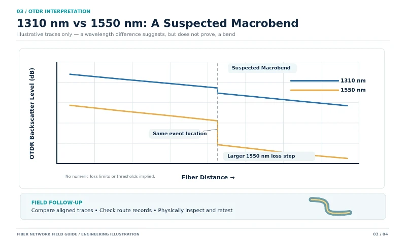
For many conventional single-mode fibers, the guided field extends farther from the core at longer wavelengths. A tight bend can therefore produce a more noticeable loss at 1550 nm than at 1310 nm. This wavelength dependence makes dual-wavelength OTDR testing useful when a link has an unexplained increase in attenuation.
A practical comparison is made at the same physical event, using appropriate settings for each wavelength. A nonreflective loss step that is small at 1310 nm but distinctly larger at 1550 nm raises suspicion of macrobending. The size of that difference is not a universal pass/fail threshold: fiber design, event characteristics, pulse settings and measurement uncertainty still matter.
Tests at 1625 nm can offer greater macrobend sensitivity for suitable single-mode systems. The VIAVI technical paper on macrobend detection explains the use of multiple OTDR wavelengths and wavelength-dependent event comparison. It does not follow that a measured loss at 1625 nm can be converted to 1550 nm or 1310 nm by a fixed ratio.
Testing an active link requires a separate decision. Standard out-of-service OTDR procedures should be performed on an isolated fiber. Where the network permits in-service testing, use the approved out-of-band wavelength, filtering or wavelength-separation arrangement, and instrument designed for that network. VIAVI's in-service PON troubleshooting guidance describes why the test wavelength and network isolation arrangement matter. Do not connect an ordinary OTDR to an unknown live port and assume that operating at 1625 nm makes the test safe.
How to Detect Macrobending with an OTDR
Dual-wavelength OTDR testing is most useful when the results can be compared with the original link record and a physical route drawing. The aim is to identify a suspected location, not to label every nonreflective event as a bend.
- Confirm the symptom and test condition. Record the affected fiber, service wavelength, observed loss or alarm, and whether the path is available for out-of-service testing. Keep any earlier acceptance traces for comparison.
- Inspect accessible connections first. Check and clean patch-cord and panel interfaces before starting an extended fault search. Contamination can increase insertion loss and complicate the interpretation of a downstream trace. Follow a consistent fiber optic connector cleaning procedure.
- Prepare the launch and receive fibers. Use a launch cord of suitable length and matching fiber type to move the first connector beyond the OTDR's initial dead zone. Use a receive cord when the far-end connector must be measured.
- Set the measurement conditions. Choose the correct fiber type, group index or refractive-index setting, wavelength, range, pulse width and averaging time. A shorter pulse can separate closely spaced events but may provide less dynamic range on a long link. Do not assume that one pulse width works for both a short panel jumper and an outside-plant span.
- Collect the 1310 nm and 1550 nm traces. Test the same fiber under comparable conditions. Store both traces and confirm that their distance scales and event positions align before comparing event loss.
- Examine the suspected event. Look for a nonreflective step whose measured loss is more pronounced at the longer wavelength. Review nearby reflective events, dead zones and trace noise; an automatic event label should not be treated as conclusive.
- Correlate distance with the route. Compare the reported optical distance with splice plans, slack storage and known enclosure positions. OTDR distance is calculated from optical propagation; it need not match a straight-line ground distance or every cable-route measurement exactly.
- Inspect and retest. At an accessible suspected location, relieve the bend or mechanical stress without exceeding the cable's handling limits. Repeat the measurement using comparable settings. A reduction at the same event, together with an acceptable end-to-end result, supports the diagnosis.
For setup, trace interpretation and dead-zone considerations beyond this specific fault, the broader OTDR fiber testing procedure provides useful background. An OTDR trace should also be saved after repair so later maintenance crews can compare it with the restored condition.
Can an OTDR Detect Microbending?
An OTDR can sometimes reveal attenuation associated with microbending, but it cannot reliably identify every microbend or confirm the underlying mechanical cause from the trace alone. Distributed pressure may increase the slope of the backscatter trace over a section. In another cable, the effect may be too short, too small or too irregular to resolve as a distinct feature.
When microbending is suspected, compare several kinds of evidence:
- Does the measured end-to-end insertion loss exceed the earlier result or the project acceptance limit?
- Does attenuation vary with temperature or mechanical loading?
- Is the route exposed to tie pressure, clamp pressure, conduit damage or cable compression?
- Does relieving a safe, accessible pressure point produce a repeatable reduction in loss?
- Is there visible jacket damage, or evidence that an internal tube may have been permanently deformed?
A distributed loss change is not unique to microbending. Differences in fiber characteristics, a damaged section, poor test settings or changes in the launch condition may also affect the trace. A diagnosis becomes stronger when measurements, site conditions and response to a controlled correction agree.
Bend Loss vs Splice Loss vs Connector Faults
Macrobends and fusion splices can both appear as nonreflective OTDR events. A clean connector usually produces a reflective event, but a contaminated or damaged connection may combine reflectance and excess insertion loss. These broad patterns are useful; none is an infallible identification method.
| Observation | Possible Explanation | What to Check Next |
|---|---|---|
| Nonreflective event with much higher loss at 1550 nm | Possible macrobend | Compare both wavelengths, route records and the physical bend |
| Nonreflective event near a documented splice | Fusion splice, local stress or a bend close to the joint | Check splice location, nearby stored fiber and bidirectional measurement |
| Reflective event with elevated loss | Connector, mechanical joint or other reflective discontinuity | Inspect and clean accessible connectors; check reflectance and location |
| Gradual increase in attenuation across a section | Distributed stress, fiber characteristic change or measurement artifact | Review cable condition, test settings and earlier traces |
| Unusual negative event loss or different results from opposite ends | Backscatter mismatch or one-way measurement bias | Use appropriate bidirectional analysis rather than accepting one result |
Fiber-to-fiber differences can make a splice appear to have negative loss in one test direction or unusually high loss in the other. Fluke Networks' guidance on OTDR and OLTS testing explains why bidirectional OTDR measurements improve the interpretation of splice events. A large wavelength difference suggests a possible bend, but it does not automatically eliminate every splice- or fiber-transition-related explanation.
When a suspect event coincides with a joint, consider optical fiber splice loss together with the routing of the adjacent slack. A mechanically stressed loop just outside the splice protector may be the problem even when the splice itself is acceptable.
Which Test Tool Answers Which Question?
| Tool | Useful Result | Important Limitation |
|---|---|---|
| Optical loss test set (OLTS), or calibrated light source and power meter | End-to-end insertion loss against a defined reference | Does not identify where the loss occurs |
| Optical time-domain reflectometer (OTDR) | Distance to events, trace shape and comparative attenuation data | Event loss is inferred from backscatter; resolution and backscatter mismatch affect results |
| Visual fault locator (VFL) | Visible-light indication of some accessible breaks or tight bends | Not a reliable method for locating faults inside opaque, jacketed or long cable routes |
| Transceiver digital optical monitoring (DOM/DDM) | Operational transmit/receive power trends and alarms, where supported | Not a substitute for calibrated cable acceptance testing |
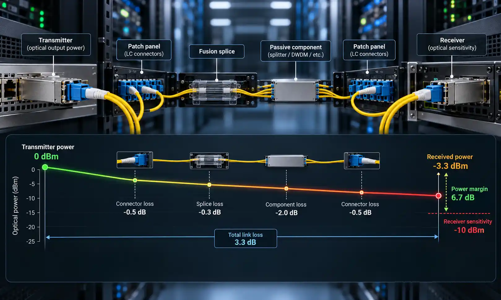
OTDR testing and insertion-loss testing serve different purposes. An OTDR is valuable for finding a suspected loss event, while OLTS or a properly referenced source and meter establishes the total link loss for acceptance against the applicable requirements. The equipment and method must match the fiber type and the link being tested.
Does G.657 Bend-Insensitive Fiber Prevent Bend Loss?
No. Bend-insensitive single-mode fiber is designed to reduce macrobending loss compared with conventional designs under specified conditions. It does not make the cable immune to tight routing, pressure, tensile overload or mechanical damage.
ITU-T G.657 (08/2024) defines categories of bending-loss-insensitive single-mode fiber with different bending performance requirements. G.657.A1, G.657.A2 and G.657.B3 are not interchangeable statements about what every finished cable can tolerate. The cable's installation instructions still govern its complete construction, including buffers, strength members and jacket.
A cable built with G.657 fiber may tolerate a tighter fiber routing condition while still suffering damage if it is crushed or pulled against a sharp edge. For troubleshooting, compare the installed fiber type and cable datasheet before deciding whether a given route is acceptable.
Corrective Actions for Common Field Conditions
Excess Slack in a Patch Panel
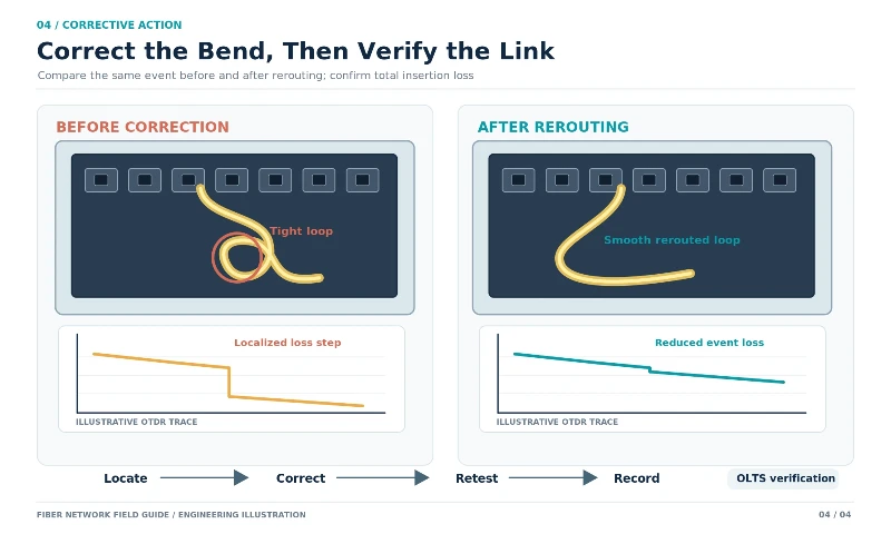
Inspect how the fibers enter the tray, pass the adapters and return into storage. If an intact jumper is pinched into a tight loop, reroute the slack through the intended guides and keep the bend within the cable specification. Avoid pulling against the connector boot or introducing a second sharp turn to remove the first one.
Stressed Fiber Inside a Splice Closure
Check splice-protector placement, tray storage and cable entry points. A fiber optic splice closure can protect the joint while still containing an over-tight storage loop if fibers were routed incorrectly. Restore the tray arrangement without putting strain on the splice. If the coating, tube or fiber is damaged, follow the approved repair or resplicing procedure.
Tight Ties or Clamps
Release the cable carefully and inspect the jacket. If measurements improve and there is no sign of structural damage, restore the run with suitable supports that do not squeeze the cable. If the jacket remains flattened or the buffer is damaged, the section may need replacement even if a short-term measurement improves.
Crushed Duct or Outside-Plant Cable
A crushed or deeply deformed cable should not be declared serviceable merely because one wavelength still passes traffic. Assess the mechanical damage and follow the cable manufacturer's repair criteria. Permanent deformation or broken fibers normally call for replacement of the affected section and restoration of the splice records.
Loss That Changes with Temperature
Review the dates of link alarms against ambient conditions, then inspect enclosure entrances, exposed sections and areas where the cable is restrained. Repeat testing under documented conditions when possible. The aim is to find a reproducible relationship between cable stress and attenuation, not to assign a microbend diagnosis solely from the season.
How to Verify That a Bend-Loss Repair Worked
Correcting the visible route is only the first part of the job. A repair should leave a measurable and documented improvement without introducing a new problem elsewhere on the fiber.
- Record the physical condition and location before changing the cable route.
- Capture or retain the pre-repair trace and insertion-loss result, including test wavelengths and settings.
- Reroute, relieve stress or replace the affected section using the approved procedure.
- Repeat the OTDR measurement with comparable conditions. Confirm whether the suspected event has been reduced or removed and whether another event has appeared.
- Measure total end-to-end insertion loss where required, and compare it with the project acceptance criteria and the link's optical budget.
- Update splice records, enclosure labels, route drawings and stored traces so the next test has a reliable reference.
A lower OTDR event value alone does not establish that the entire optical channel meets its requirement. Conversely, a link that comes back online is not automatically a verified repair. The final decision should account for both physical cable condition and measured optical performance.
Frequently Asked Questions
Does higher loss at 1550 nm than at 1310 nm prove a bend?
No. On conventional single-mode fiber, a localized event with greater loss at 1550 nm is a strong macrobend indicator. Confirm the event location, test conditions and physical cable routing. Other event characteristics and measurement effects may complicate the comparison.
Can an OTDR detect microbending?
It may reveal the extra attenuation associated with microbending, but it cannot reliably identify every microbend as a distinct event or determine the mechanical cause from a trace alone. Distributed stress may appear as a change in attenuation slope, while shorter or weaker effects may not be resolved.
How can I distinguish a bend from a bad fusion splice?
Compare the event at suitable wavelengths, check whether its distance coincides with a documented splice and inspect the surrounding stored fiber. A pronounced longer-wavelength loss difference suggests a bend; bidirectional OTDR testing can improve splice-loss evaluation. Physical confirmation remains important.
Why is 1625 nm used for bend detection?
For many conventional single-mode fibers, longer test wavelengths can make macrobending more apparent. A suitable 1625 nm OTDR can therefore help locate bends that are less conspicuous at shorter wavelengths. In-service use requires an approved network-specific setup and suitable filtering or isolation.
Can G.657 fiber still suffer bend or compression loss?
Yes. G.657 fiber offers specified macrobending performance, not immunity to mechanical abuse. Jacket compression, excessive tension, damaged buffers and routing outside the finished cable's limits can still cause attenuation or physical failure.
Will bend loss disappear after the cable is rerouted?
Loss from an undamaged fiber held in an excessively tight loop may decrease when the bend is relieved. Loss caused by persistent compression or permanent cable damage may not. Retesting and inspection determine whether rerouting was sufficient or the affected cable section must be replaced.
What Confirms a Bend-Loss Repair?
A suspect bend should be diagnosed from more than one signal: wavelength-dependent behavior, event location, the cable's mechanical condition and the result of a controlled repair. Dual-wavelength OTDR testing is particularly helpful for macrobending, while microbending often requires investigation of pressure, cable construction and environmental stress. Once the physical cause has been addressed, record both the event-level result and the total link performance before returning the fiber to service.