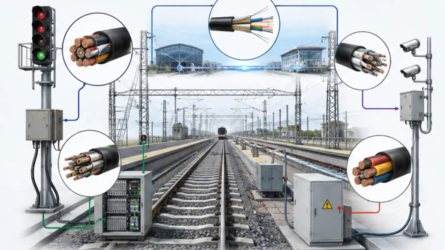
Railway cables support signalling, control, communications, monitoring, safety systems and power distribution across modern rail networks. The category includes very different cable constructions, from copper signal circuits and control cables to long-distance fiber optic backbones and power cables.
That is why there is no useful answer to the question "What is the best railway cable?" without first defining the system function, installation route and governing specification. A cable installed in a tunnel, a trackside duct, a station equipment room and a rail vehicle can face different electrical, mechanical, environmental and fire-performance requirements.
This guide explains the main railway cable types, the parameters that matter during selection, the difference between commonly confused terms such as screening and armoring or LSZH and fire resistance, and the information engineers and procurement teams should prepare before requesting a quotation.
What Are Railway Cables?
Railway cables are electrical or optical cables used for power, signalling, control, communication or data transmission within railway and mass-transit systems. Depending on the application, they may contain copper conductors, optical fibers or both, with additional elements for electromagnetic protection, mechanical reinforcement, water blocking, fire performance or environmental durability.
The phrase "railway cable" therefore describes an application category, not one universal construction. The technical specification still has to define what the cable must carry, where it will be installed and which tests or approvals apply.
Fixed Railway Infrastructure vs Rolling Stock
This distinction should be made at the beginning of a project. Fixed infrastructure includes trackside routes, signalling systems, stations, tunnels, equipment rooms, telecommunications networks and power infrastructure. Rolling stock cables are installed on locomotives, passenger cars, metro vehicles and other rail vehicles.
The two environments can differ in vibration, mechanical movement, installation rules, fire strategy, voltage systems and approval requirements. For example, IEC 62995:2018 addresses installation of cabling on railway rolling stock. It should not be treated as a generic product standard for every fixed-infrastructure cable.
Where Railway Cables Are Used
Railway networks combine multiple electrical and communications systems, often along the same corridor. Typical cable applications include:
- Railway signalling and interlocking interfaces
- Trackside control and monitoring equipment
- SCADA and remote monitoring
- Station-to-station telecommunications
- CCTV and security systems
- Passenger information systems
- Operational voice and data networks
- Tunnel communications
- Equipment control circuits
- Power distribution to railway infrastructure
The route matters almost as much as the function. A cable may be installed indoors, in a tunnel, in a tray, in a duct, underground, directly exposed outdoors or close to electrified railway equipment. Those conditions influence jacket materials, water protection, screening, reinforcement, fire requirements and installation limits.
Main Types of Railway Cables

Railway Signal Cables
Railway signal cables carry electrical information between signalling, monitoring and control equipment. Their construction may use individual cores, pairs or other conductor arrangements, with screened or unscreened designs depending on the electrical system and electromagnetic environment.
Conductor size alone is not enough to define a signal cable. Depending on the signalling circuit, the specification may also control conductor resistance, insulation resistance, capacitance, impedance, conductor arrangement, screen construction or other electrical parameters. The connected equipment and system design determine which values matter.
Railway Fiber Optic Cables
Fiber is widely used for long-distance and high-capacity railway communications. Optical transmission is inherently resistant to electromagnetic interference because the information is carried by light rather than electrical current. NIST research on optical-fiber feedthroughs and EMI likewise distinguishes the fiber itself from the electromagnetic behavior of the complete connector and enclosure system.
Typical railway uses include telecommunications backbones, CCTV, station links, SCADA, monitoring networks and data transmission. A railway project may use constructions from the broader fiber optical cable family, but the final design still has to match the railway route and specification.
Important fiber parameters can include:
- Fiber type and optical transmission requirements
- Fiber count and spare-fiber strategy
- Link distance and attenuation budget
- Cable tensile and crush performance
- Minimum bending requirements
- Water-blocking design
- Metallic or non-metallic strength members
- Fire and smoke performance where applicable
- Splicing, termination and maintenance strategy
Railway Control Cables
Control cables carry commands and control signals between equipment, panels, automation systems and field devices. They may look similar to signal cables, but similar appearance does not make the two interchangeable. Electrical characteristics, conductor arrangement, voltage rating, screening and connected equipment requirements must be checked.
Railway Communication and Data Cables
Railway communication networks can use both copper and fiber. Copper remains useful where equipment interfaces require electrical transmission, for short links, or where an installed system is designed around copper technology. Depending on the application, relevant constructions can overlap with the broader network cable category.
Fiber is generally attractive when the project needs longer transmission distances, higher bandwidth, electrical isolation or immunity to electromagnetic interference. The system architecture should decide the medium rather than a blanket preference for copper or fiber.
Railway Power Cables
Power cable selection is a separate engineering task from signal or communication cable selection. The specification normally needs to define rated voltage, load current, conductor size, short-circuit duty where applicable, installation method, ambient conditions, grouping or derating conditions, mechanical protection and required fire performance.
A cable suitable for signalling or communications should never be assumed to be suitable for power distribution simply because both products are described as railway cables.
Railway Cable Selection Matrix
| Application | Common Cable Family | Parameters to Evaluate First |
|---|---|---|
| Railway signalling | Signal or control cable | Electrical characteristics, conductor arrangement, EMC, screening, installation route |
| Station-to-station backbone | Fiber optic cable | Distance, bandwidth, fiber type, fiber count, optical budget, route protection |
| Trackside communications | Fiber or copper communication cable | Water, UV, temperature, mechanical risk, EMC, maintenance access |
| CCTV and monitoring | Fiber, data or control cable | Bandwidth, distance, interface type, environment, power architecture |
| Tunnel and station systems | Communication, control, signal or fiber cable | Fire tests, smoke, halogen or acidity requirements, circuit integrity if required |
| Outdoor duct route | Signal, fiber, communication or power cable | Water penetration, pulling tension, crush, bending, route length, joint strategy |
| Power distribution | Power cable | Voltage, current, conductor size, short-circuit duty, installation and protection |
This matrix is a starting point for technical evaluation, not a product specification. The final design should be checked against the railway operator, EPC, signalling supplier, national authority or project documents that govern the installation.
How to Choose Railway Cables: 7 Technical Checks

1. Define the System Function and Interface
Start with what the cable connects and what it must carry. Is the circuit used for signalling, control, telecommunications, video, monitoring data or power? Then identify the interface requirements of the connected equipment.
For copper circuits, this may include conductor configuration, conductor size, rated voltage and specified electrical characteristics. For fiber links, it may include fiber type, fiber count, link distance, optical budget and termination method.
Beginning with cable construction before the system function is defined reverses the engineering logic. Armor, screening and jacket material are secondary choices until the transmission requirement is clear.
2. Define the Railway Installation Environment
Record the full route rather than describing the project only as "railway." Useful questions include:
- Is the route indoors, outdoors or both?
- Does it pass through a tunnel, station or public area?
- Will the cable be installed in duct, tray, conduit or directly buried?
- Is the route exposed to sunlight or standing water?
- What installation pulling forces and bend limits are expected?
- Is the cable vulnerable to impact, crushing, rodents or ground pressure?
- Will sections run close to traction power or other electrical infrastructure?
For outdoor and harsh-environment connections, related outdoor cable assembly concepts can be useful when evaluating sealing, connector protection and environmental exposure, although the railway project specification remains the controlling document.
3. Evaluate Railway EMC and Screening Requirements
Electrified railways contain traction power, switching equipment, return currents, communications systems and other potential electromagnetic sources. The IEC 62236 series on railway electromagnetic compatibility provides a railway EMC framework, but it does not mean every cable needs the same screen construction.
For copper signal and control circuits, screening should be specified in response to the circuit design and electromagnetic environment. Foil, braid and combined screens have different electrical and mechanical characteristics. The complete screen design also includes bonding, grounding and termination practices; a screen that is poorly integrated into the installation may not deliver the intended EMC performance.
Optical fiber itself avoids electrical signal coupling from EMI. However, the complete cable may still contain metallic armor, strength members or moisture barriers, so bonding, lightning exposure and induced-current considerations can still apply to the overall construction.
4. Match Mechanical Protection to the Actual Risk
Armoring and reinforcement are primarily used to address mechanical risks such as impact, crushing, installation stress or external damage. They are not substitutes for electromagnetic screening.
A cable can be screened without armor, armored without a screen, both screened and armored, or neither. The correct combination comes from two separate questions: what electromagnetic protection does the circuit require, and what physical protection does the route require?
For more background on construction choices, see this guide to armored fiber optic cable. In a railway project, the armor material should still be checked against mechanical loads, corrosion conditions, bonding requirements and project approvals.
5. Specify Fire, Smoke and Halogen Performance by Test
Terms such as flame-retardant, LSZH and fire-resistant describe different properties. They should not be used as interchangeable shorthand.
Flame propagation concerns how a cable behaves when exposed to flame. For example, IEC 60332-1-2:2025 specifies a vertical flame-propagation test for a single insulated wire or cable.
Smoke density is a separate characteristic. IEC 61034-2 describes measurement of smoke density from cables burning under defined conditions.
Halogen and acidity-related performance is addressed by another test family. IEC 60754-1 covers determination of halogen acid gas content from cable materials, while IEC 60754-2 addresses acidity and conductivity of gases evolved during combustion.
Fire resistance or circuit integrity is about maintaining a required function under a defined fire test. For example, IEC 60331-1:2018 covers circuit-integrity testing under fire with mechanical shock for certain cables up to 0.6/1.0 kV and above 20 mm overall diameter; IEC 60331-2 addresses smaller diameters within its scope.
This is why "LSZH railway cable" and "fire-resistant railway cable" are not synonyms. A project can require low smoke, low halogen or low acidity characteristics without requiring continued circuit operation during fire, or it can require both. The exact test method, classification and acceptance criteria should be written into the specification.
For a basic material comparison, the site also has an explainer on PVC and LSZH cable jackets.
6. Convert Environmental Risks into Measurable Cable Requirements
Outdoor railway routes can expose cables to water, UV radiation, temperature cycling, soil, mechanical stress and rodents. Instead of requesting a vague "outdoor railway cable," convert those risks into parameters that can be checked on a datasheet or test report.
Depending on the route, useful requirements may include:
- Operating and installation temperature ranges
- Water penetration or water-blocking performance
- UV resistance for exposed jackets
- Tensile load and crush resistance
- Minimum bend radius during installation and operation
- Rodent protection where the route requires it
- Chemical or oil resistance where exposure is expected
- Corrosion suitability for metallic components
Not every railway cable needs every protective feature. Extra construction increases diameter, weight, cost and installation complexity, so each feature should solve an identified risk.
7. Confirm Standards, Operator Specifications and Approval Scope
A railway project can be governed by several layers of requirements at the same time: international standards, national standards, operator specifications, signalling-system documents, fire-safety requirements, EPC specifications and project-specific approvals.
The key question is not simply "Which railway cable standard applies?" but "Which document controls this cable in this specific application?"
Before approving a product, confirm:
- Whether the cable is for fixed infrastructure or rolling stock
- The exact standard number and edition or revision
- Whether the cited standard is a product standard, installation standard or test method
- Any operator-specific approval or qualified-product requirement
- Required type tests, routine tests and inspection documents
- Whether third-party certification is required
- Any country-specific fire, electrical or construction requirements
This scope check matters because railway standards are not interchangeable. IEC 62995, for example, concerns rolling-stock cabling installation, while IEC 62236 addresses railway EMC. IEC 60332, IEC 60754, IEC 61034 and IEC 60331 are test families for specific fire-related characteristics. None of those references, by itself, proves that a cable is approved for a particular railway operator or project.
Copper vs Fiber Optic Cable in Railway Networks
Copper and fiber are complementary technologies rather than universal substitutes.
When Copper Is the Better Fit
Copper remains appropriate for electrical signalling, control circuits, low-voltage interfaces, equipment connections and systems designed around conductive transmission. It can also carry power where the circuit is designed for that purpose.
The trade-offs are that electrical performance can be affected by distance, resistance, capacitance, impedance and electromagnetic conditions. Those factors are especially important when the connected signalling or control equipment has tightly defined circuit requirements.
When Fiber Is the Better Fit
Fiber is attractive for long-distance, high-bandwidth or electrically isolated links. It is particularly useful for telecommunications backbones, CCTV aggregation, monitoring networks and station-to-station communications.
Its immunity to EMI applies to the optical transmission medium itself. The full cable design still needs mechanical, environmental and fire evaluation, especially if metallic components are included.
Screening vs Armoring: A Practical Distinction
These two terms are often placed next to each other in specifications, but they solve different engineering problems.
- Screening: primarily addresses electromagnetic coupling and electrical noise.
- Armoring or reinforcement: primarily addresses physical protection such as impact, crush or external mechanical damage.
For a screened copper signal cable, the engineer may need to define screen coverage, screen material, drain wire, bonding method or grounding concept. For an armored cable, the engineer may instead be concerned with tensile strength, crush resistance, installation damage, corrosion or bonding of metallic armor.
Writing "screened armored railway cable" without defining either risk may produce a cable that is heavier and more expensive while still failing the actual EMC or mechanical requirement.

Illustrative Railway Cable Selection Scenario
Consider an illustrative station-to-station communications link running through an electrified railway corridor. The route includes outdoor duct sections and equipment rooms at both ends.
The first decision is the transmission medium. If the required bandwidth and link distance favor fiber, an optical backbone removes the copper signal path from the railway EMI environment. The next decisions are construction-related: fiber type and count, optical budget, water blocking for the duct route, tensile and crush performance for installation, and whether metallic reinforcement is acceptable.
At the station entries, the fire strategy may introduce additional smoke, halogen or flame-propagation requirements. Rather than writing "LSZH fireproof fiber cable," the specification should name the required tests or classifications. If circuit integrity during fire is not required for that communication function, a circuit-integrity test should not be added automatically.
The final step is approval scope. The engineer checks the operator or project documents to confirm the applicable cable specification, test reports, documentation package and any approved-manufacturer requirement. This sequence turns a broad product request into a set of decisions that a manufacturer can actually evaluate.

Frequently Asked Questions About Railway Cables
Q: Are all railway cables armored?
A: No. Armor should be used where the installation requires additional mechanical protection. Indoor, protected or all-dielectric applications may use unarmored constructions, while exposed or mechanically demanding routes may require reinforcement.
Q: Are all railway cables LSZH?
A: No. Fire and smoke requirements depend on the installation, applicable regulations and project specification. Tunnels, underground stations and public areas often receive closer fire-safety review, but the required test methods still need to be defined.
Q: Is LSZH the same as fire-resistant?
A: No. LSZH relates to smoke and halogen or acidity characteristics of cable materials under specified test conditions. Fire resistance or circuit integrity concerns maintaining a defined electrical or optical function during a specified fire test.
Q: Why is fiber used near electrified railways?
A: Optical transmission is immune to electromagnetic interference, which makes fiber useful for communications in electrically noisy environments. The complete cable still needs to be checked for metallic components, mechanical protection, water exposure and fire requirements.
Q: What parameters matter most for a railway signal cable?
A: The answer depends on the signalling circuit, but the specification may include conductor configuration, conductor size, resistance, insulation performance, capacitance, impedance, screening, rated voltage, fire performance and installation requirements. The connected signalling equipment determines which electrical parameters are critical.
Q: Which railway cable standard should I specify?
A: There is no single standard that covers every railway cable application. Identify the cable function and installation scope first, then use the operator, project, national and international documents that apply. Also distinguish between product standards, installation standards and test methods.
Conclusion
Railway cable selection works best as a system-engineering exercise rather than a search for a generic product labeled "railway cable." Start with the function and interface, then define electrical or optical parameters, installation environment, EMC exposure, mechanical risks, fire tests, environmental protection and approval scope.
The strongest specification is one that converts broad terms such as "screened," "armored," "LSZH" or "fire-resistant" into measurable requirements and named test methods. That gives engineers, procurement teams and manufacturers a common technical basis for comparing cable constructions and documenting compliance.