Moving from 800G to a 1.6T optical transceiver is not simply a matter of doubling port speed. The transition pushes host electrical signaling to the 200G-per-lane class and forces engineers to revalidate the physical layer: transceiver form factor, host interface, PMD, fiber type, connector architecture, channel loss, thermal budget, firmware, and link training all have to match.
That does not mean every 800G fiber plant must be replaced. Whether existing cabling can stay depends on the specific 1.6T optical interface being deployed. A native parallel-optics PMD, a dual-interface design, and a wavelength-multiplexed duplex-fiber PMD can require very different fiber counts and connector systems.
1.6T Starts with 200G-Class Lanes
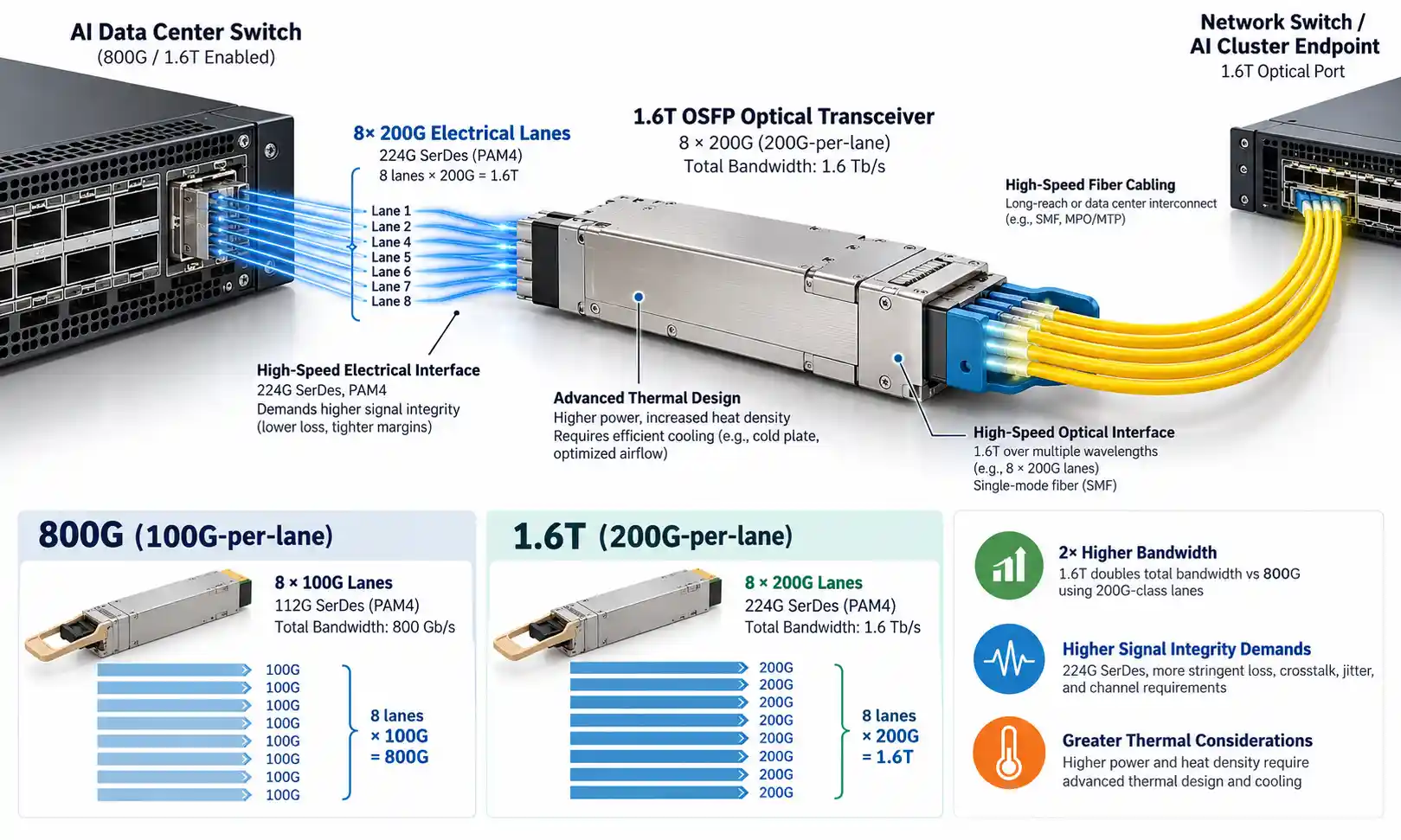
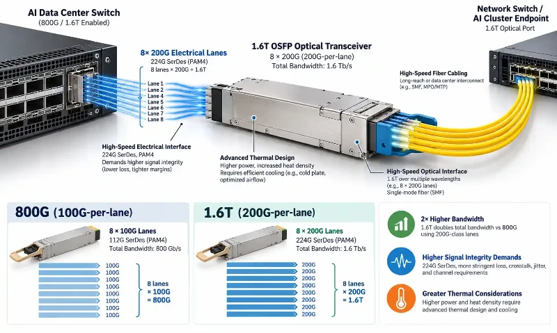
The 1.6T label describes aggregate port bandwidth. The underlying electrical interface moves to the 200G-per-lane class, often referred to as 224G SerDes in the component ecosystem because of the encoded line rate used to deliver roughly 200 Gb/s of payload per lane.
In September 2026, the Ethernet Alliance demonstrated 1.6T OSFP connectivity, 224G SerDes technology, and link training in a live multi-vendor environment. Its ECOC 2026 interoperability demonstration is useful evidence that the 1.6T ecosystem is moving beyond isolated prototypes and into practical interoperability work.
The electrical and optical details matter because faster lanes leave less tolerance for channel loss, reflections, timing error, and poor signal integrity. A deployment that worked comfortably at a previous generation should therefore be revalidated rather than assumed to be plug-and-play.
IEEE P802.3dj Is Still Moving Through the Standards Process
As of September 29, 2026, IEEE P802.3dj has not yet become a finalized published amendment. The IEEE 802.3 ballot announcement page lists Draft 3.3 in its third Standards Association recirculation ballot, opened September 25, 2026 and scheduled to close October 10, 2026.
This distinction matters when writing specifications or procurement requirements. Draft parameters, vendor implementations, MSA specifications, and demonstrated interoperability can all guide engineering work, but they should not be described as if the final IEEE amendment has already been published.
The IEEE P802.3dj public area remains the best reference point for current task-force materials covering 200 Gb/s, 400 Gb/s, 800 Gb/s, and 1.6 Tb/s Ethernet.
800G vs 1.6T: What Changes at the Physical Layer?
| Design Area | 800G Generation | 1.6T Generation | Deployment Impact |
|---|---|---|---|
| Host lane class | Commonly 100G-class electrical lanes | 200G-class electrical lanes | Host channel and SerDes validation become more demanding |
| Aggregate bandwidth | 800 Gb/s | 1.6 Tb/s | Twice the port throughput |
| Module power | Depends on PMD and implementation | Generally higher for comparable DSP-based pluggable implementations | Switch thermal and power class must be checked against the actual module |
| Optical interface | Varies by PMD | Varies by PMD and vendor implementation | Existing fiber may or may not be reusable |
| Channel loss | PMD-specific | PMD-specific | Use the actual PMD limit, not a generic 1.6T loss number |
| Bring-up | Platform dependent | 200G-class host interfaces place greater emphasis on link training and host/module compatibility | Firmware and management compatibility become part of deployment validation |
For readers comparing earlier high-speed generations, existing fiber optic transceiver architectures provide a useful baseline: the move to higher lane rates changes more than raw bandwidth, even when the external module remains a familiar pluggable format.
OSFP1600 Is Important, but It Is Not the Only 1.6T Form Factor
The OSFP MSA defines OSFP1600 as a 200G-per-lane variant of the OSFP family. The current OSFP Module Specification distinguishes OSFP1600 from earlier OSFP and OSFP800 variants while retaining the general OSFP ecosystem.
OSFP is therefore one of the leading 1.6T pluggable form factors, particularly for high-power switch applications. It should not, however, be described as the only possible 1.6T form factor. QSFP-DD1600, OSFP-XD, and platform-specific implementations also exist in the broader ecosystem.
The practical rule is simple: select the module only after confirming the host cage, mechanical variant, power class, cooling method, management interface, and PMD supported by the actual switch or NIC.
Does 1.6T Require New Fiber Cabling?
No universal answer applies. The requirement depends on the optical PMD and the module's external interface.
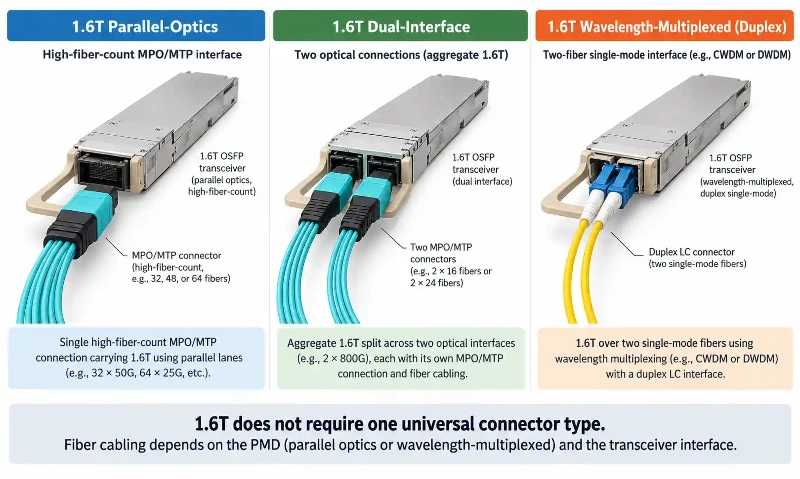
The same 1.6T aggregate rate can be presented through parallel single-mode fibers, multiple optical interfaces, or wavelength-multiplexed duplex-fiber architectures. That is why a migration plan should begin with the transceiver interface rather than with a blanket assumption such as "1.6T requires MPO-16."
Parallel-Optics Interfaces
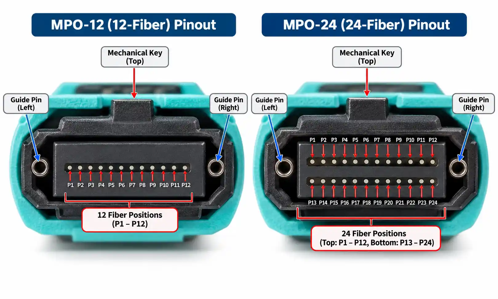
Native parallel-optics designs use multiple optical lanes in parallel. Where the PMD specifies an MPO-16 or another multi-fiber interface, the structured cabling must match the fiber count, keying, polarity, end-face geometry, and insertion-loss requirements of that exact interface.
If the existing plant already uses compatible MPO/MTP cable assemblies, portions of the installed infrastructure may remain useful. But compatibility has to be checked at the PMD and connector level; a legacy MPO-12 trunk is not automatically interchangeable with an MPO-16 interface.
Dual-Interface Modules
Some 1.6T modules divide the aggregate bandwidth into two lower-rate optical interfaces. In these designs, the cabling may look more like two independent optical links than one native 1.6T parallel interface.
This architecture can create migration opportunities where an existing structured fiber plant already supports the lower-rate interface. The correct connector cannot be inferred from the words "2xDR4" or "2xFR4" alone without checking the actual module specification: parallel DR-style interfaces and wavelength-multiplexed FR-style interfaces can use different fiber presentations.
Duplex-Fiber WDM Interfaces
Wavelength-multiplexed FR-class designs reduce external fiber count by carrying multiple wavelengths over duplex single-mode fiber. These interfaces should not be grouped together with parallel MPO architectures simply because the total module bandwidth is 1.6T.
Where a 1.6T design presents duplex single-mode ports, existing OS2 single-mode patch cabling may remain suitable if connector type, loss, reach, and return-loss requirements are met.
Do Not Assume All 1.6T Links Require APC
Connector end-face requirements are PMD-specific.
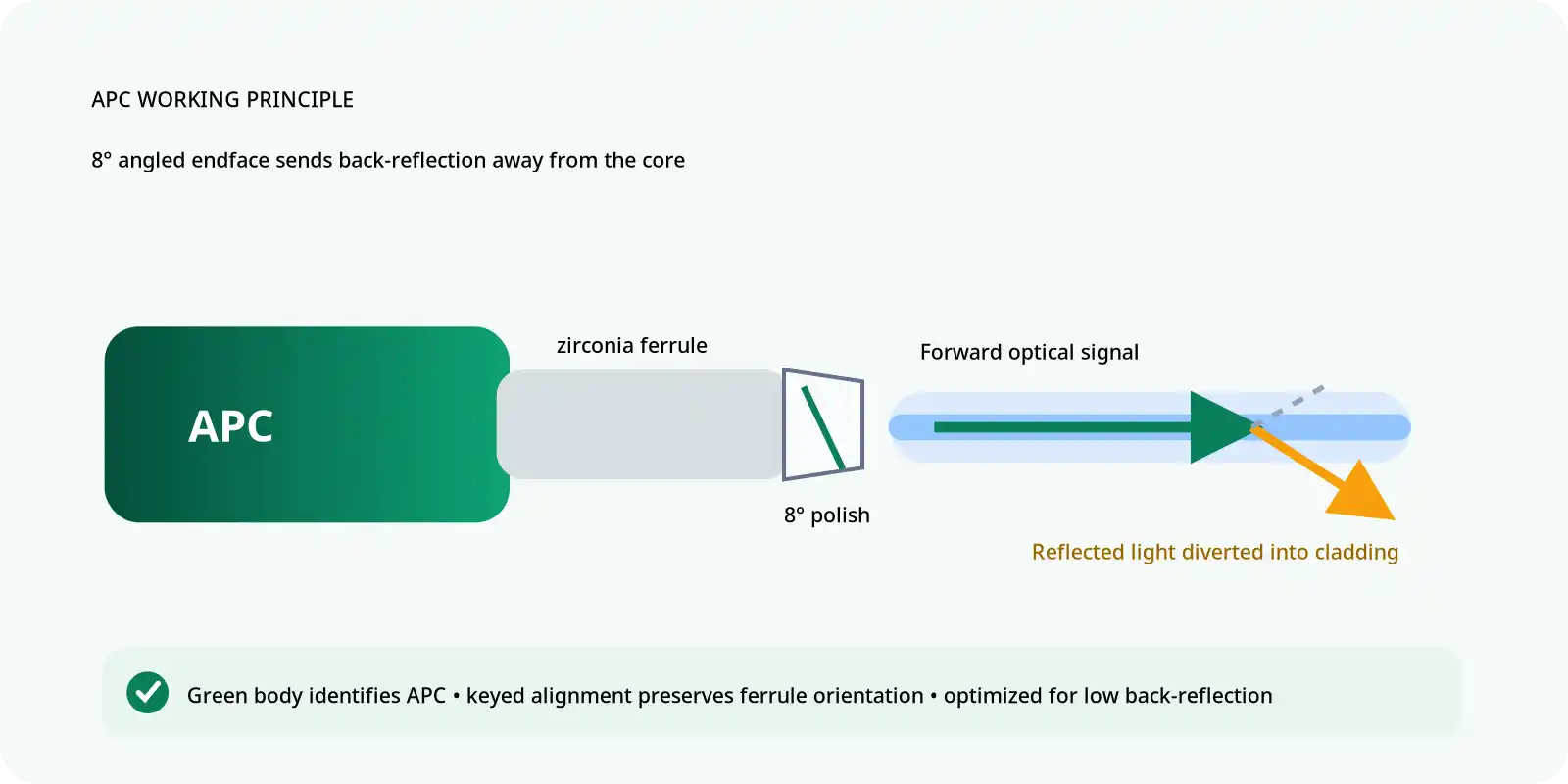
For example, IEEE P802.3dj work for native parallel 1.6TBASE-DR8 has used an angled MPO interface as the specified MDI. That does not mean every 1.6T single-mode optical link must use APC at every connection point.
Other PMDs and vendor implementations can use different interfaces, including duplex-fiber connectors. The correct rule is to follow the MDI and return-loss requirements of the actual PMD and transceiver instead of converting one DR8 requirement into a universal 1.6T cabling rule.
This also means fiber optic connector selection should be made after the PMD is chosen, not before.
Design the Fiber Plant Around the PMD-Specific Loss Budget
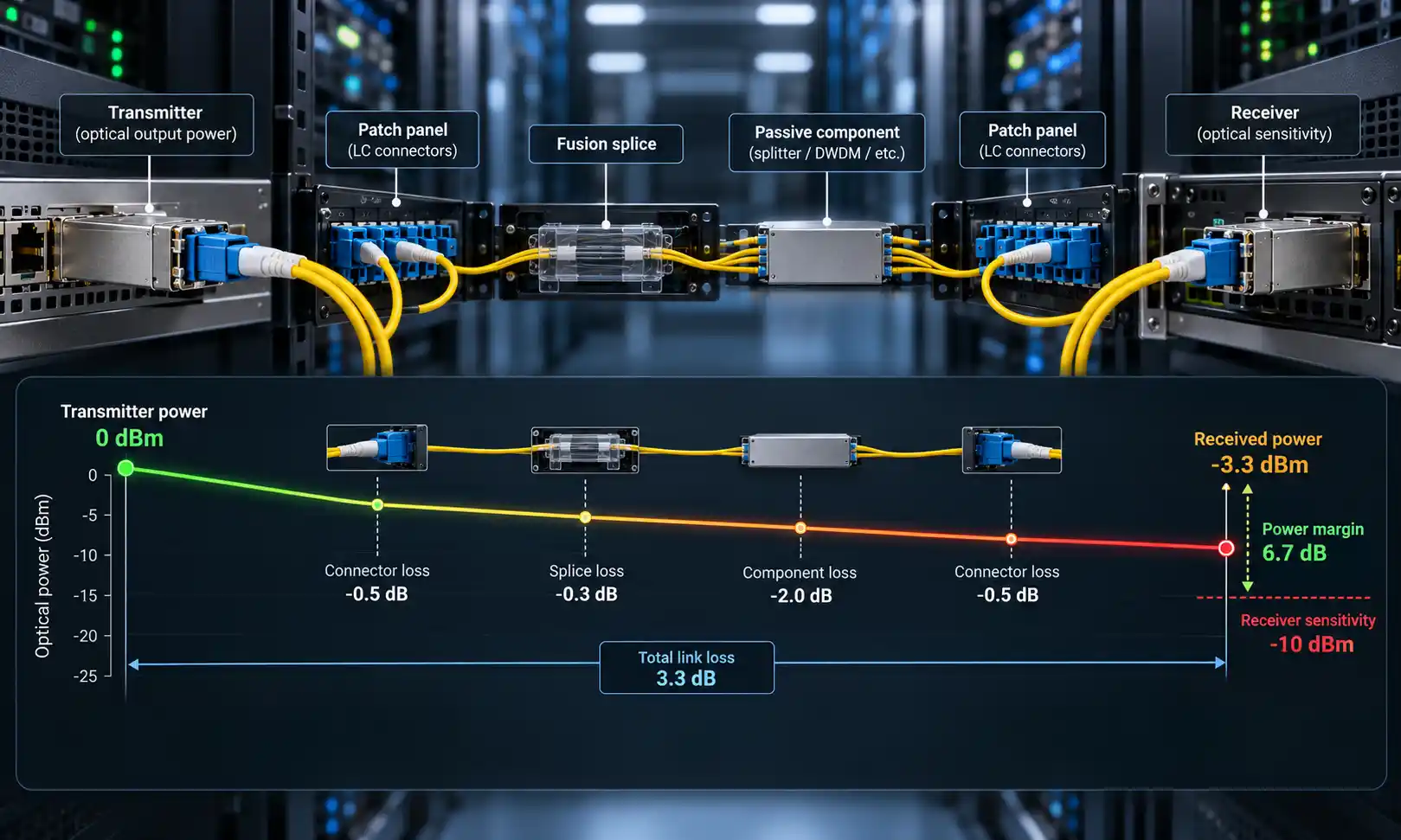
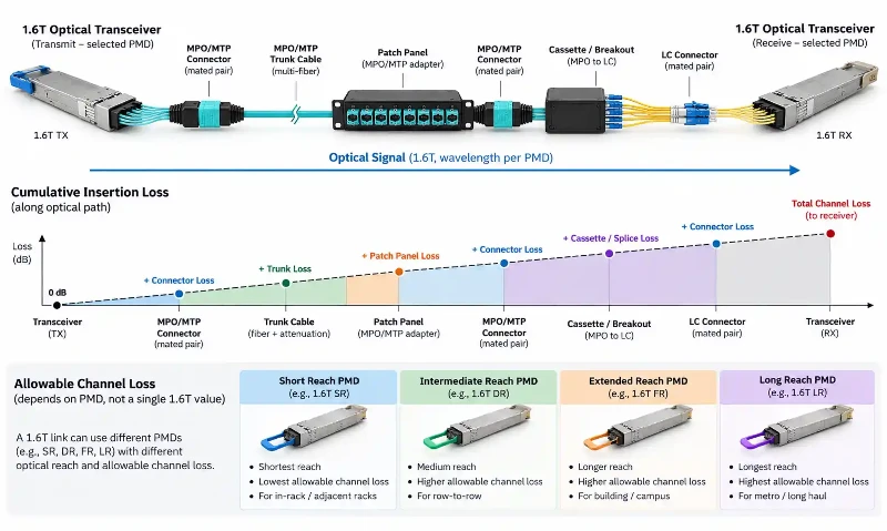
There is no single "1.6T insertion-loss budget" that applies to every optical interface. DR, FR, and other PMDs can have different channel definitions, reach limits, connector assumptions, and reflectance requirements.
Engineers should therefore map the full optical path and apply the limit defined for the actual module and PMD. The channel may include:
- Fiber attenuation
- Mated connector pairs
- MPO/MTP trunks
- Cassettes and breakout assemblies
- Patch panels
- Splices
- Adapters
- Other passive optical components
Dense structured cabling is where apparently small losses can accumulate. A design with several MPO/MTP trunk and patching points should be evaluated component by component instead of using a generic "low-loss" assumption for the entire path.
The same principle applies to duplex links. Use the measured or specified insertion loss of the actual cable assembly and compare the total path against the PMD limit with the required engineering margin.
200G Per Lane Does Not Make Multimode Fiber Irrelevant
Current IEEE P802.3dj 1.6TbE optical work is centered on single-mode-fiber PMDs, so SMF is the main reference for the first wave of standardized 1.6T Ethernet optical interfaces.
That should not be rewritten as "200G per lane can only use single-mode fiber." IEEE P802.3ds is a separate active project specifically developing 200 Gb/s per wavelength multimode-fiber PHYs. Its 2026 task-force materials include work on OM3, OM4, and OM5 reach and 200G/lane MMF links.
For current 1.6T deployment planning, follow the fiber type required by the selected PMD. For longer-term infrastructure planning, keep the P802.3ds work in view rather than assuming multimode development has stopped at earlier lane rates.
Power and Thermal Design Must Be Checked Per Module
1.6T DSP-based pluggable optics generally place more pressure on switch cooling than earlier generations, but a single universal wattage should not be used as a procurement threshold.
Module power varies with PMD, reach, DSP implementation, laser architecture, and form factor. The OSFP MSA is designed to support high-power modules, but the actual switch must still support the power class and thermal profile of the chosen transceiver.
Before approving a deployment, verify:
- Maximum module power from the vendor data sheet
- Host port power class
- Cage and heatsink compatibility
- Airflow or liquid-cooling design
- Thermal behavior at full port population
This is more reliable than assuming every 1.6T optic consumes the same amount of power.
Breakout Changes the Cabling Decision
One reason 1.6T modules can be useful during migration is that the aggregate port may support lower-rate breakout modes. Common implementation goals include dividing one 1.6T port into multiple 800G, 400G, or 200G logical links.
The cabling required for that breakout depends on the module's optical presentation. A parallel multi-fiber port may use a harness that maps optical lanes into lower-rate destinations, while a dual-interface module may expose two independent optical groups.
When a breakout architecture uses multi-fiber assemblies, polarity must match the Tx/Rx lane mapping of the transceiver and the far-end equipment. This is where the design of MPO/MTP harness cables becomes part of the logical port plan rather than only a physical cabling choice.
Link Training and Management Become Part of Deployment Validation
At 200G-class electrical lane rates, the host/module electrical channel becomes less forgiving. Link training, equalization, firmware support, and module management therefore matter more during bring-up.
Do not reduce troubleshooting to optical Rx power alone. A port can fail to initialize even when optical power appears reasonable if the host electrical channel, firmware, management interface, or module configuration is incompatible.
Deployment validation should include:
- Host ASIC and transceiver interoperability
- Supported management-interface revision
- Electrical link-training status
- Pre-FEC and post-FEC error behavior
- Optical Tx/Rx levels
- Channel insertion loss
For physical-layer acceptance, a fiber installation and testing toolkit is relevant only after the PMD's actual test limits and procedures are defined.
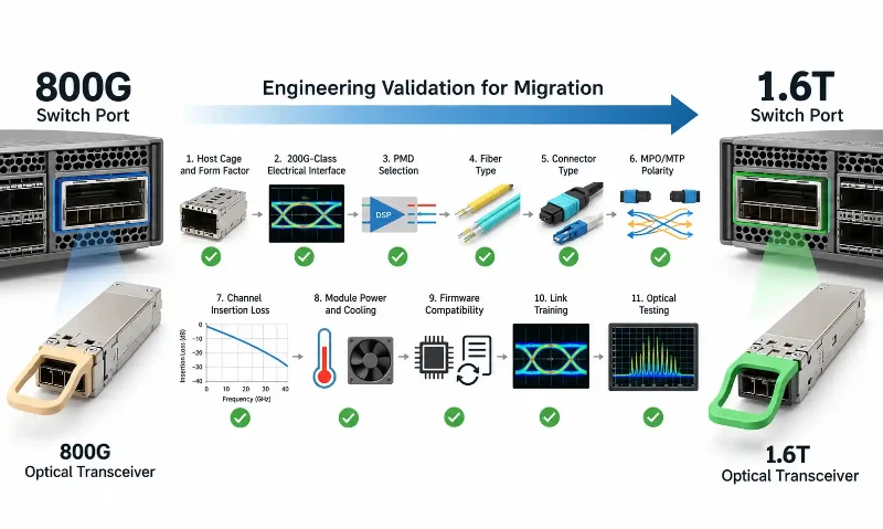
800G to 1.6T Migration Checklist
| Migration Area | What to Verify |
|---|---|
| Switch cage | Form factor, mechanical variant, power class, heatsink, and airflow |
| Host interface | Support for the required 200G-class electrical lane architecture and link training |
| PMD | DR, FR, or other optical interface and its defined reach |
| Fiber type | SMF or MMF exactly as required by the selected PMD |
| Connector | MPO-16, another MPO/MTP interface, duplex connector, or other MDI defined by the module |
| Polarity | Lane mapping for any parallel-optics or breakout path |
| Channel loss | PMD-specific insertion-loss and return-loss limits |
| Firmware and management | Host software, module management, and interoperability requirements |
| Testing | Optical loss, Tx/Rx power, FEC behavior, link training, and production/field test plan |
Step 1: Confirm the Host Before Buying the Optic
Verify the switch or NIC's supported form factor, electrical lane rate, management interface, power class, and cooling method. A mechanically similar module is not automatically electrically or thermally compatible.
Step 2: Choose the PMD by Reach and Fiber Architecture
Select the optical PMD according to distance, fiber availability, connector density, structured-cabling design, and interoperability requirements. Do not choose the fiber connector first and force the optical interface to fit it later.
Step 3: Audit the Existing Fiber Plant
Record fiber type, fiber count, connector type, polarity, patch points, cassette count, measured insertion loss, and spare capacity. This determines what can be reused and what has to change.
Step 4: Recalculate the Channel Loss
Use the PMD-specific channel limit and the actual installed component losses. Extra patching points that were harmless at an earlier architecture may consume too much of the available budget in a tighter design.
Step 5: Validate Breakout and Polarity
If the design uses 2x800G, 4x400G, 8x200G, or another breakout mode, verify both the logical port configuration and the physical Tx/Rx mapping through the trunk and harness system.
Step 6: Test Host-to-Module Bring-Up
Before volume deployment, validate link training, firmware, management, FEC behavior, and optical performance on the actual switch, module, cabling, and far-end device combination.
Frequently Asked Questions
Does 1.6T need MPO-16?
No. MPO-16 is relevant to specific native parallel-optics interfaces such as DR8 implementations, but other 1.6T modules can use different multi-fiber or duplex-fiber interfaces. Follow the transceiver's defined MDI.
Can existing 800G fiber support 1.6T?
Sometimes. The glass itself may remain usable if the new PMD uses the same fiber type and the installed channel meets the required loss, reflectance, connector, polarity, and reach limits. The transceiver interface determines whether the existing connector and fiber-count architecture can be reused.
What does 200G per lane mean?
It means the 1.6T aggregate port is built from electrical or optical lanes in the 200 Gb/s class rather than the 100 Gb/s class commonly associated with the previous 800G generation. Component vendors often use the term 224G SerDes for the corresponding encoded electrical interface technology.
Is OSFP required for 1.6T?
No. OSFP1600 is a major 1.6T pluggable form factor, but it is not the only option in the ecosystem. The required form factor is determined by the host platform.
Does 1.6T require OM5?
No universal 1.6T rule requires OM5. Current P802.3dj 1.6TbE optical PMDs are centered on single-mode fiber, while the separate IEEE P802.3ds project is developing 200G-per-wavelength multimode PHYs. Use the fiber specified by the actual PMD.
Final Takeaway
The move from 800G to 1.6T is best treated as a physical-layer revalidation, not an automatic fiber-plant replacement.
Start with the host platform and PMD. From there, verify form factor, power, fiber type, connector interface, polarity, channel loss, breakout mapping, firmware, and link training. Existing 800G cabling may remain valuable where the new optical interface is compatible, but 1.6T should never be approved on aggregate speed or nominal reach alone.
The most durable migration strategy is to keep the fiber plant modular, documented, and measurable so that each new transceiver generation can be evaluated against real channel data rather than assumptions.