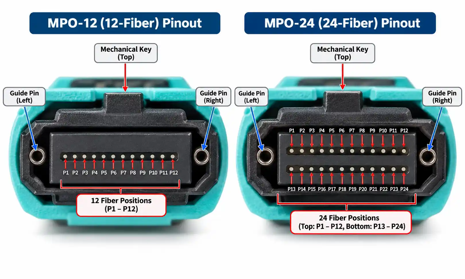
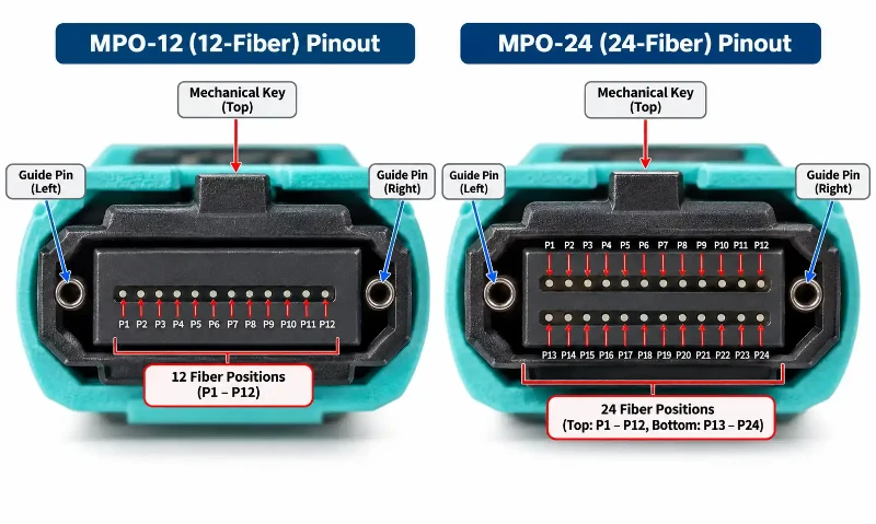
An MPO connector "pinout" usually refers to the numbered fiber positions and how those positions map from one end of a cable to the other. The metal guide pins are a separate mechanical feature. With the key up and the cable connector endface facing you, a 12-fiber MPO is numbered P1 through P12 from left to right. A 24-fiber MPO uses two rows: P1 through P12 on the top row and P13 through P24 on the bottom row.
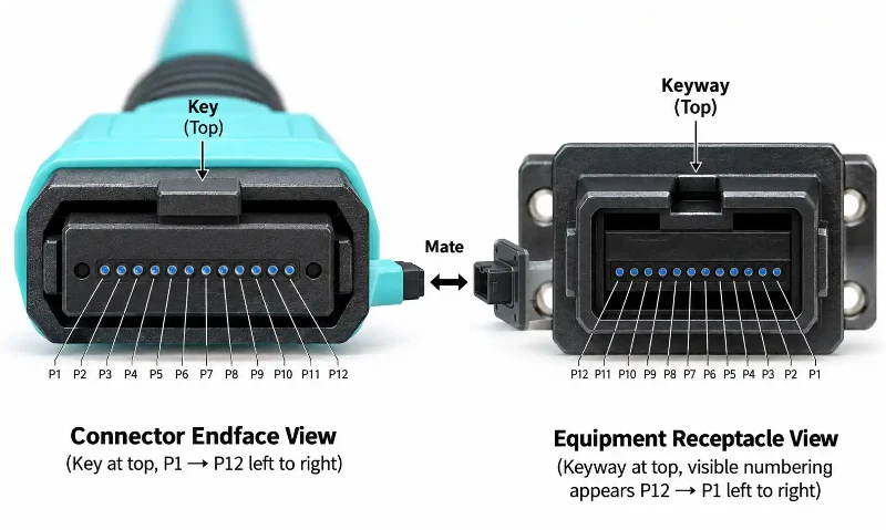
The viewing direction matters. A drawing of a cable connector endface can look reversed compared with a drawing made while looking into an equipment receptacle. Before tracing Tx and Rx lanes, confirm whether the diagram shows the plug endface or the device port. This distinction is one of the most common sources of MPO pinout mistakes in high-density MPO/MTP cable assemblies.
MPO Pinout Quick Reference
| Item | 12-Fiber MPO | 24-Fiber MPO |
|---|---|---|
| Fiber positions | 12 | 24 |
| Ferrule layout | One row of 12 positions | Two rows of 12 positions |
| Connector-end numbering with key up | P1 to P12 from left to right | Top: P1 to P12; Bottom: P13 to P24 |
| Male/female definition | Based on guide pins | Based on guide pins |
| Polarity | Commonly described with Type A, B, or C cable mapping | Must be checked against the actual two-row assembly specification |
| Tx/Rx assignment | Defined by the PMD or equipment interface | Defined by the PMD or equipment interface |
The connector geometry itself is standardized separately from the network application. IEC 61754-7-1 defines one-row MPO connector interfaces, while IEC 61754-7-2 covers two-row MPO interfaces. TIA also maintains optical-fiber cabling requirements in the current ANSI/TIA-568.3-E Optical Fiber Cabling Component Standard.
MPO Guide Pins and Fiber Positions Are Not the Same Thing
The terms male and female describe the connector's alignment hardware, not its optical lane numbering.
- Male or pinned MPO: the connector has two alignment pins.
- Female or unpinned MPO: the connector has two guide holes that receive the mating pins.
Those guide pins align the MT ferrules during mating. They do not become P1, P2, or any other optical position, and changing the gender of a field-configurable connector does not renumber the fibers inside the ferrule. The ferrule, spring, guide pins, housing, boot, and other MPO connector components perform different mechanical functions from the fiber-position map.
This distinction matters when a drawing uses the word "pinout." In electrical connectors, a pinout normally describes conductive pins. With MPO, users often use the same word when they actually mean fiber-position numbering or fiber mapping.
How to Read an MPO Connector Pinout Diagram
Before reading the position numbers, establish three things:
- Are you looking at the cable connector endface or into an equipment receptacle?
- Is the mechanical key shown at the top or bottom?
- Does the diagram show fiber positions only, or does it also assign Tx and Rx lanes for a specific transceiver?
Cable Connector Endface View
For the convention used in this article, look directly at the cable connector endface with the key at the top. On a 12-fiber connector, P1 is at the far left and P12 is at the far right.
| Key Up - Cable Connector Endface | P1 | P2 | P3 | P4 | P5 | P6 | P7 | P8 | P9 | P10 | P11 | P12 |
|---|
Equipment Receptacle View
When you look into the mating receptacle from the opposite side, the same physical positions appear mirrored. With the keyway at the top, an equipment drawing may therefore show P12 on the left and P1 on the right.
Cisco documents this exact viewing convention for an MPO-12 module receptacle: when looking into the receptacle with the mechanical key on top, the fibers are numbered 12 through 1 from left to right. Its MPO connector technical specifications also show how the same physical positions can receive PMD-specific Tx and Rx assignments.
Why Some MPO Pinout Diagrams Look Reversed
Two diagrams can both be correct even when P1 appears on opposite sides. The reason is usually viewing direction, not a different numbering standard.
A cable connector endface and the mating equipment receptacle face each other. Looking directly at each surface means viewing the same interface from opposite directions. The result is a mirror image. That is why an engineer should never copy a Tx/Rx position from a device drawing into a cable drawing without checking the perspective first.
A practical rule is to label drawings explicitly as connector endface view or receptacle view. If the plug includes a Position-1 indicator on the body, use it together with the key orientation rather than relying on left/right position alone.
12-Fiber MPO Pinout and Position Numbering
A standard 12-position MPO ferrule places all fibers in one row. With the connector endface facing you and the key up, the sequence runs from P1 on the left to P12 on the right.
| 12-Fiber MPO | P1 | P2 | P3 | P4 | P5 | P6 | P7 | P8 | P9 | P10 | P11 | P12 |
|---|
The numbering stays the same whether the plug is male or female. What changes from cable to cable is how those numbered positions map to the far end.
MPO-12 Type A, Type B, and Type C Fiber Mapping
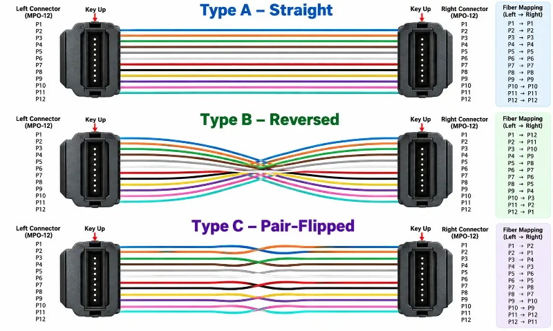
Type A, Type B, and Type C describe cable fiber mapping. They are related to complete channel polarity methods, but a cable type and an end-to-end cabling method are not the same thing. When specifying MPO/MTP trunk cabling, both the cable mapping and the rest of the channel must be checked.
Type A: Straight-Through Mapping
Type A keeps each numbered position aligned with the same numbered position at the far end.
| Near End | Far End |
|---|---|
| P1 | P1 |
| P2 | P2 |
| P3 | P3 |
| P4 | P4 |
| P5 | P5 |
| P6 | P6 |
| P7 | P7 |
| P8 | P8 |
| P9 | P9 |
| P10 | P10 |
| P11 | P11 |
| P12 | P12 |
Type B: Reversed Mapping
Type B reverses the position order across the cable.
| Near End | Far End |
|---|---|
| P1 | P12 |
| P2 | P11 |
| P3 | P10 |
| P4 | P9 |
| P5 | P8 |
| P6 | P7 |
| P7 | P6 |
| P8 | P5 |
| P9 | P4 |
| P10 | P3 |
| P11 | P2 |
| P12 | P1 |
Type C: Adjacent-Pair Flipped Mapping
Type C swaps adjacent fiber pairs.
| Near End | Far End |
|---|---|
| P1 | P2 |
| P2 | P1 |
| P3 | P4 |
| P4 | P3 |
| P5 | P6 |
| P6 | P5 |
| P7 | P8 |
| P8 | P7 |
| P9 | P10 |
| P10 | P9 |
| P11 | P12 |
| P12 | P11 |
The important point is that Type A/B/C describes how fibers are routed through a cable assembly. It does not, by itself, tell you which position is Tx or Rx on a particular optical module.
24-Fiber MPO Pinout: Two Rows, 24 Positions
A 24-fiber MPO uses two rows of 12 positions within the MT ferrule. With the connector endface facing you and the key up, the top row is P1 through P12 and the bottom row is P13 through P24.
| Top Row | P1 | P2 | P3 | P4 | P5 | P6 | P7 | P8 | P9 | P10 | P11 | P12 |
|---|---|---|---|---|---|---|---|---|---|---|---|---|
| Bottom Row | P13 | P14 | P15 | P16 | P17 | P18 | P19 | P20 | P21 | P22 | P23 | P24 |
The extra row increases density, but it also means a 24-fiber mapping should be read from the actual assembly specification rather than inferred by simply applying a one-row 12-fiber diagram twice. A 24-fiber MPO trunk cable may be used as a backbone, conversion link, or application-specific parallel interface, and each use can impose a different mapping requirement.
The same viewing-direction rule still applies. On an equipment receptacle drawing, both rows can appear mirrored. Cisco, for example, documents an MPO-24 receptacle in which the top row is shown as 12 through 1 and the bottom row as 24 through 13 when viewed into the module with the keyway on top.
MPO-12 vs MPO-24: What Actually Changes?
| Feature | MPO-12 | MPO-24 |
|---|---|---|
| Fiber positions | 12 | 24 |
| Rows | 1 × 12 | 2 × 12 |
| Connector-end numbering | P1–P12 | Top P1–P12; bottom P13–P24 |
| Guide-pin gender | Male or female | Male or female |
| Fiber mapping | Often specified as Type A, B, or C | Check the two-row cable or system specification |
| Tx/Rx lanes | Application-specific | Application-specific |
| Typical cabling role | Parallel optics, trunks, breakout and conversion links | High-density trunks, breakout and application-specific parallel links |
Fiber Position Mapping Is Not the Same as Tx/Rx Assignment
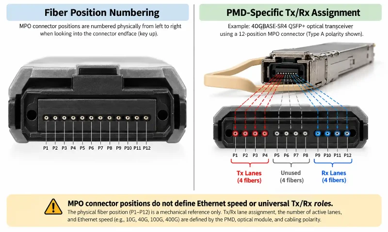
This distinction is critical. An MPO connector provides numbered optical positions. The transceiver or PMD decides which of those positions transmit, receive, or remain unused.
For example, SR4 applications use eight active fibers even when the interface is built on a 12-position MPO ferrule. Four fibers transmit, four receive, and four positions are unused. The exact Tx/Rx orientation must still be read from the transceiver or equipment documentation because a module receptacle diagram is viewed from the opposite direction from a cable endface.
The IEEE 802.3bm 100GBASE-SR4 material defines the PMD around four transmit and four receive optical lanes over multimode fiber. That optical-lane definition is separate from the cable's Type A, B, or C mapping.
Example: 40GBASE-SR4 and 100GBASE-SR4
A 12-position MPO interface is commonly used for SR4 links, with eight active fibers and four unused center positions. That is why a 40GBASE-SR4 MPO transceiver and a 100GBASE-SR4 MPO-12 transceiver can use the same basic ferrule format while carrying different per-lane data rates.
This also shows why fiber count should not be treated as an Ethernet-speed label. An MPO-12 does not mean "100G," and an MPO-24 does not mean "400G." The speed, lane count, active positions, wavelength plan, and reach are defined by the optical interface.
Breakout and Harness Cables Add Another Mapping Layer
A breakout cable converts a multi-fiber MPO interface into smaller connector groups. The fiber positions must therefore map correctly not only across the MPO ferrule but also into the breakout legs.
For example, an MPO/MTP harness cable may split parallel lanes into LC or other interfaces. In that case, the assembly drawing should identify:
- The MPO position number at the multi-fiber end
- The destination leg or duplex pair
- The Tx/Rx orientation required by the target equipment
- The polarity method used by the complete channel
Cisco's official breakout guidance provides a useful equipment-side example of how MPO-12 and MPO-24 interfaces can be mapped into lower-count links. Those examples are valuable as device-specific assignments, but they should not be generalized into a universal MPO connector pinout.
Common MPO Pinout Mistakes
1. Treating Guide Pins as Fiber Pins
The two metal guide pins align the ferrules. P1–P12 or P1–P24 are optical positions. They are different systems.
2. Ignoring the Viewing Direction
Connector endface and receptacle drawings can look mirrored. A correct position number copied from the wrong viewing perspective can reverse an entire parallel-optics lane map.
3. Assuming Male or Female Changes Fiber Numbering
Gender changes the guide-pin hardware, not the P1–P12 or P1–P24 sequence.
4. Treating Type B as a Universal Tx/Rx Rule
Type B describes reversed cable mapping. It does not mean a particular numbered fiber is always Tx or always Rx.
5. Assuming Fiber Count Defines Network Speed
Different optical PMDs can use the same MPO ferrule differently. Always verify the active-lane assignment for the actual transceiver.
6. Applying a 12-Fiber Diagram Directly to a 24-Fiber Assembly
MPO-24 has a second row and may use application-specific row and position mapping. Use the assembly drawing rather than deriving the map from a single-row cable.
How to Verify an MPO Pinout Before Installation
Before patching a parallel-optics link, verify the cable and equipment documentation against the same viewing convention.
- Confirm fiber count: 12, 24, or another MPO format.
- Confirm male or female guide-pin configuration.
- Confirm key orientation.
- Confirm whether the diagram is a connector-end or receptacle view.
- Confirm the cable mapping or polarity type.
- Confirm the transceiver's active Tx/Rx positions.
- For breakout assemblies, confirm the mapping from each MPO position to the corresponding breakout leg.
If a continuity check is needed, test the numbered positions one by one or use multi-fiber polarity test equipment that can report the complete mapping in one pass. The objective is to verify the physical route, not to infer polarity from connector color, gender, or fiber count.
FAQ: MPO Connector Pinouts
Which side is Position 1 on an MPO connector?
With the cable connector endface facing you and the key at the top, P1 is on the far left for the convention used in standard connector-end diagrams. If you are looking into an equipment receptacle, the position can appear on the opposite side because you are viewing the mating interface from the other direction.
Why does one MPO pinout show P1 on the left and another show P1 on the right?
The diagrams are probably using different viewing perspectives. A connector-end view and a receptacle view are mirror images. Check the diagram label and key orientation before comparing position numbers.
What is the difference between MPO guide pins and fiber positions?
Guide pins are the two mechanical alignment pins that define a male or pinned connector. Fiber positions are the numbered optical locations inside the ferrule, such as P1–P12 or P1–P24.
How are 24 fibers numbered in an MPO-24 connector?
With the connector endface facing you and the key up, the top row is P1 through P12 and the bottom row is P13 through P24.
Does an MPO-24 always use 12 fibers for Tx and 12 for Rx?
No. Tx/Rx assignments are application-specific. Some equipment uses row-based Tx/Rx groupings, but that is a property of the PMD or device interface, not a universal rule for every MPO-24 connector.
Does changing MPO gender change polarity?
No. Adding or removing guide pins changes male/female gender. It does not automatically change the internal fiber map. Polarity depends on how the fibers are routed from one connector end to the other.
Can a 12-fiber MPO cable be used for an 8-fiber SR4 link?
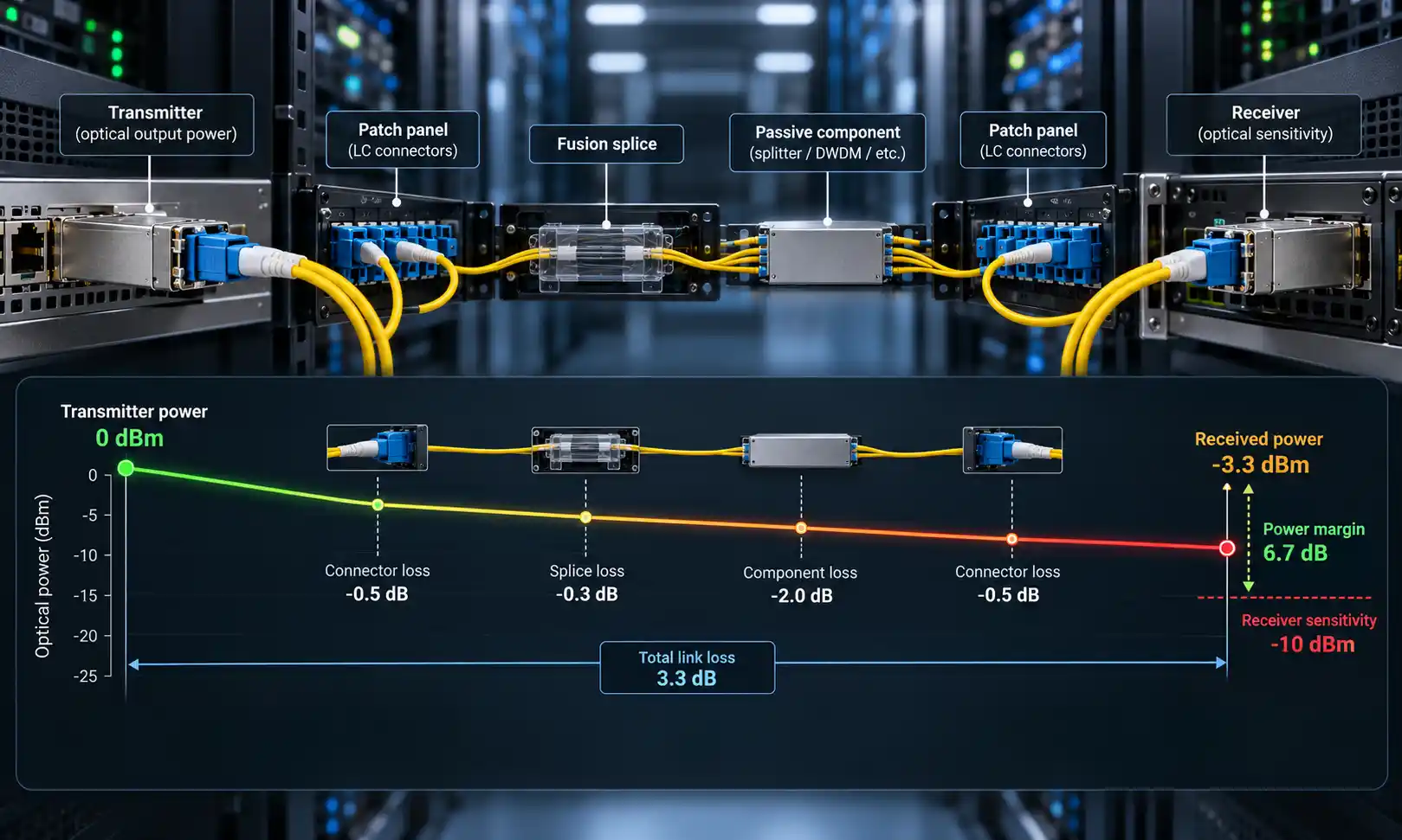
Yes. SR4 commonly uses eight active fibers in a 12-position ferrule, leaving four positions unused. Those unused fibers reduce fiber utilization but do not consume the optical power budget of the active lanes.
Final Takeaway
An MPO pinout is easiest to read when three concepts stay separate: guide-pin gender, fiber-position mapping, and transceiver Tx/Rx assignment. For a 12-fiber connector, the cable-end numbering runs P1–P12 in one row. For a 24-fiber connector, the top row is P1–P12 and the bottom row is P13–P24.
Before using any diagram, confirm the viewing direction. Then verify the cable mapping and the PMD-specific lane assignment independently. That approach avoids the most common errors caused by mirrored receptacle drawings, male/female terminology, and assumptions that fiber count alone defines the network application.