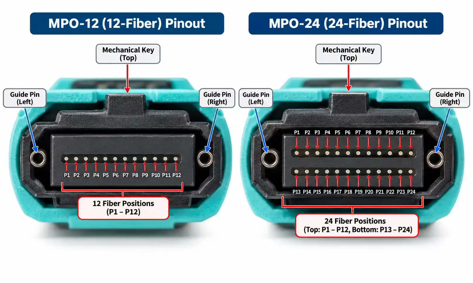
An MPO link does not have to be completely down to have a serious optical problem. In many installations, the first warning is simpler: the link powers up, but one or more fibers measure higher insertion loss than expected.
That is a different troubleshooting problem from a no-link condition. The objective is not to review every possible MPO fault. It is to answer a narrower engineering question:
Where is the extra optical loss coming from, and how can you prove which part of the channel is responsible?
The most reliable way to answer that question is to work from measurement evidence rather than replacing components by guesswork. An MPO channel may contain patch cords, adapters, cassettes, an MPO/MTP trunk cable, and equipment interfaces. A high end-to-end reading tells you the channel has a loss problem. It does not automatically tell you which component caused it.

First, Separate Excess Loss From Other MPO Problems
Insertion loss is the reduction in optical power as light travels through the passive link. A loss test compares the optical power entering the link with the power received at the far end and expresses the difference in decibels.
That sounds straightforward, but three different problems are often mixed together during MPO troubleshooting:
- Excess insertion loss: the correct fiber path exists, but too much optical power is lost.
- Polarity or mapping error: the signal reaches the wrong fiber position.
- Continuity failure: the expected optical path is interrupted.
A polarity error normally does not create attenuation simply because the mapping is different. Instead, it can make a transmitter reach the wrong receiver position or cause the test team to compare the wrong lanes. If the test results look inconsistent with the expected channel map, verify the MPO polarity method and end-to-end fiber mapping before treating every abnormal reading as a loss event.
Do Not Troubleshoot Until You Know What "Too Much Loss" Means
A measured value has little meaning without a limit to compare it with. Before opening panels or replacing a trunk, establish the expected optical-loss budget for the channel.
The budget should come from the project specification, supported application, component specifications, and the relevant cabling requirements. ANSI/TIA-568.3-E covers performance and test requirements for premises optical fiber cabling and components, while the actual application may impose its own optical limits. The TIA announcement for ANSI/TIA-568.3-E provides the standards context.
A practical passive-link budget can be represented as:
Allowed link loss = cable attenuation + allowed loss for each included connection or component
The exact terms depend on the architecture. A cassette may already include connector interfaces in its published value, for example, so avoid counting the same connection twice.
A Simple Example
Assume a project has assigned the following non-overlapping allowances to one optical path:
- three mated interfaces at 0.30 dB each;
- 0.10 dB for cable attenuation and other defined passive allowance.
The planned passive loss is therefore 1.00 dB.
If the OLTS measures 1.55 dB on one fiber, the useful troubleshooting number is not simply "1.55 dB." It is the 0.55 dB of unexplained excess loss.
That difference gives the technician something concrete to isolate.
Read the Loss Pattern Across the MPO, Not Just the Worst Number
One of the most useful advantages of multi-fiber testing is that the other fibers can act as comparison points. Instead of immediately asking "Which cable is bad?", ask "What pattern do the lane results form?"
| Observed Pattern | What It Often Suggests | Best Next Check |
|---|---|---|
| Most or all fibers are higher than expected by a similar amount | A shared interface, reference setup, worn test cord, or channel-wide condition | Validate the test reference and inspect common interfaces |
| Only one fiber is significantly high | Localized contamination, end-face defect, damaged fiber position, or a single-path problem | Inspect that position and compare it through each channel segment |
| Several neighboring fibers are high | Contamination or damage affecting one area of the rectangular ferrule | Inspect the complete ferrule surface, not only the visibly worst fiber |
| Loss changes substantially after disconnecting and reconnecting | Contamination, mating quality, seating, or connector wear | Inspect, clean when needed, remate once, and retest consistently |
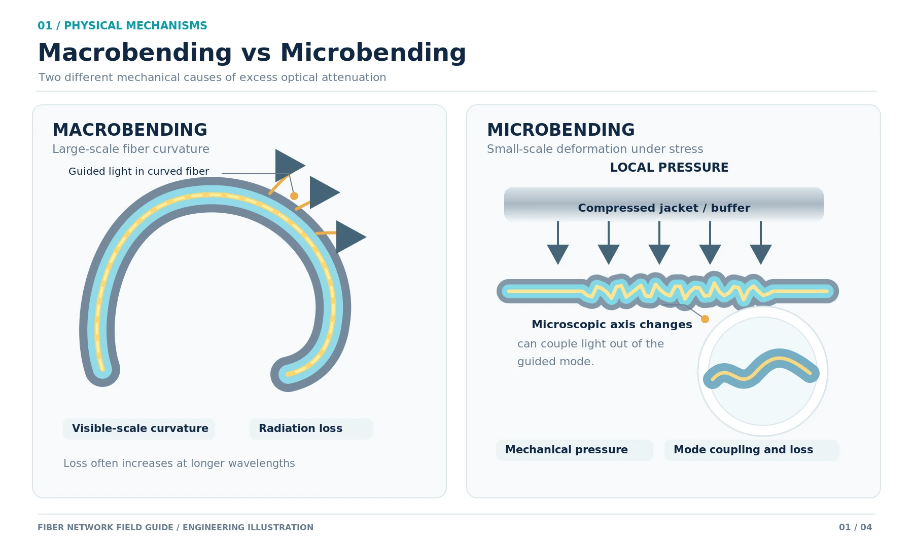
| Higher-wavelength OTDR testing shows a much stronger event | Possible bend or mechanical stress | Check routing, bend radius, cable management, and the event location |
These patterns are diagnostic clues, not automatic proof. Their value is that they tell you where to collect the next piece of evidence.

Step 1
This is the step most likely to prevent unnecessary rework.
Testing an MPO link is more complicated than testing a single-fiber connector because the test setup has to deal with multiple fiber positions, pinning, key orientation, and sometimes breakout interfaces. The Fiber Optic Association notes that MPO testing can carry additional measurement uncertainty and that worn reference cables can make measured losses rise across the test set. Its reference on testing multifiber array connectors is useful background for this issue.
Before accepting a high-loss result, confirm:
- the tester is configured for the correct fiber type and wavelength;
- the reference method matches the project test procedure;
- the launch and receive assemblies are compatible with the connector under test;
- the MPO test cords have the correct pin/no-pin mating arrangement;
- the lane map used by the tester matches the actual channel;
- reference cords are clean, undamaged, and within their usable service condition;
- the reference has not been disturbed or reset inconsistently between comparative measurements.
If the problem appeared after changing an MPO test cord, adapter, or reference configuration, investigate the measurement chain before opening the permanent cabling.
For a refresher on pinning and mating compatibility, see the site's guide to MTP/MPO male and female connector configurations.
Step 2
Contamination is especially important with MPO connectors because several fibers share one rectangular ferrule. A particle or residue does not have to affect every position equally. One part of the ferrule can be clean while another area produces elevated loss.
IEC 61300-3-35:2022 defines procedures and criteria for visual inspection of fiber-optic connector end faces. For rectangular ferrules, the standard's scope makes whole-ferrule contamination relevant rather than limiting attention to one fiber core. It also makes an important distinction: visual inspection supports cleanliness assessment, but it does not replace optical performance measurements such as attenuation or return loss. See the official IEC 61300-3-35:2022 publication page.
A sound field sequence is:
- inspect the connector end face;
- clean it if the inspection indicates cleaning is required;
- inspect again;
- mate the connector correctly;
- repeat the same loss test without changing unrelated test conditions.
A drop in loss after this sequence is useful evidence. Repeated cleaning without inspection is not. It can waste time and, with poor handling, create additional wear or contamination.
For more detail on contamination mechanisms and prevention, use the site's existing guide to fiber end-face pollution prevention rather than turning the loss investigation into a separate cleaning tutorial.
Step 3
An average MPO loss value can hide the lane that actually matters.
Suppose an MPO-12 assembly returns eleven lanes between 0.75 and 0.86 dB, while one lane measures 1.42 dB. Reporting "average loss is acceptable" would miss the important result. The useful question is why one path differs materially from the population.
For each tested fiber, record:
- fiber position or lane identifier;
- measured loss;
- test wavelength;
- direction where applicable;
- previous baseline value, if available;
- project limit;
- difference from both the limit and neighboring lanes.
This is especially valuable on existing installations. A result that technically passes but has increased by 0.4 dB from its commissioning baseline may deserve attention even if it has not yet crossed the formal pass/fail limit.
Step 4
End-to-end OLTS testing answers one question very well: How much optical power is the complete link losing?
It does not automatically answer: Which interface caused the loss?
If the link contains multiple passive sections, divide the path logically. A cassette-based architecture might look like:
Equipment patch cord → cassette → MPO trunk → cassette → equipment patch cord

The troubleshooting objective is to shorten the unknown part of that chain.
When the architecture and maintenance rules permit it, compare measurements with known-good patch cords, alternate cassette positions, or accessible segment tests. Change one variable at a time. If replacing a patch cord reduces the same lane from 1.50 dB to 0.85 dB, you have much stronger evidence than you would get from replacing three components at once.
If cassettes are part of the channel, treat them as real optical components rather than transparent boxes. Internal fanout connections and mating interfaces contribute to the total path. The site's MPO/MTP LGX cassette section can help identify the type of transition hardware being used in the link.
Step 5
OLTS and OTDR results are complementary, but they are not interchangeable.
What the OLTS Tells You
An optical loss test set measures total end-to-end insertion loss. That is the measurement you need when deciding whether the completed passive link stays within its defined loss limit.
Fluke Networks' OLTS and OTDR testing strategy explains that OLTS testing is used for total link loss, while OTDR testing characterizes individual events along the path.

What the OTDR Tells You
An OTDR is most valuable once you know the link is abnormal but still need to know where the abnormal event is located.
It can help identify:
- a high-loss connection;
- a reflective event;
- a bend or mechanically stressed section;
- an unexpected additional connection;
- the approximate distance to a fault.
For MPO systems, OTDR work may require breakout or channel-specific test arrangements. Short data-center links can also place events close together, so launch/receive fibers, pulse width, dead zones, and test configuration matter.
Do not use an OTDR trace as a substitute for the final end-to-end insertion-loss result. Use it to locate and characterize the event, correct the problem, and then repeat the required loss test.
Step 6
A trunk should be replaced only when the evidence points to the trunk.
If the same high-loss lane remains after test-reference validation, connector inspection, patch-cord substitution, and cassette isolation, the trunk becomes a stronger suspect. At that point, compare the abnormal lane with the other fibers through the trunk section and check the cable route for mechanical stress.
Look specifically for:
- tight bends at cabinet entry points;
- cable compressed by doors, covers, or tray hardware;
- pulling damage near the connector transition;
- excessive tension transferred to the MPO connector;
- sharp changes in loss near a known routing event;
- a lane that was already marginal in the factory or commissioning record.
If the installation uses both multimode and single-mode systems, do not apply the same loss assumptions automatically. Fiber type, wavelength, link architecture, and supported optics all affect the acceptance criteria. The existing single-mode vs multimode fiber guide provides the broader transmission context.
A Worked Diagnostic Example
Consider a 12-fiber MPO backbone that fails its project loss limit on fibers 5 and 6. The remaining ten fibers are tightly grouped around the expected result.
The team could approach the problem in this order:
- Check the measurement system. A known-good reference is verified, and the same two lanes remain high.
- Inspect the MPO ferrules. Contamination is found near the center of one ferrule. The connector is cleaned, inspected again, and retested.
- Compare the result. Fiber 5 returns to the normal group, but fiber 6 remains approximately 0.45 dB higher than neighboring lanes.
- Segment the channel. The patch cord and cassette path are substituted with known-good components. Fiber 6 remains high.
- Characterize the remaining path. OTDR testing identifies an abnormal event at a distance consistent with the trunk route near a cable-management transition.
- Inspect the physical route. The trunk is found tightly compressed at the identified location.
- Correct and verify. The routing condition is corrected and the link is retested with the required OLTS procedure.
The key point is not that this sequence will describe every failure. It shows how each measurement reduces uncertainty. The trunk is not blamed at Step 1, and it is not cleared merely because its connectors look clean.
Common Reasons MPO Loss Investigations Go Wrong
Using a Published "Typical Loss" as the Pass/Fail Limit
Typical performance, maximum component specification, channel budget, and application limit are not the same thing. Use the value that applies to the actual acceptance requirement.
Looking Only at the Highest-Loss Fiber
The distribution across all lanes contains diagnostic information. One outlier means something different from a uniform 0.3 dB shift across the entire ferrule.
Changing Several Components Before Retesting
If the result improves after replacing a patch cord, cassette, adapter, and test jumper simultaneously, you have restored service but learned almost nothing about the fault.
Assuming a Polarity Problem Is an Attenuation Problem
Wrong mapping can produce failed service or misleading lane comparisons without introducing a high-loss optical event. Confirm which fiber is actually being measured.
Accepting an OTDR Location Without Final OLTS Verification
Locating a bad event is not the same as proving that the corrected channel now meets the required total insertion-loss limit.
Frequently Asked Questions
What is considered high insertion loss for an MPO cable?
There is no single dB value that applies to every MPO cable or channel. The limit depends on the component specification, number of connections, fiber type, wavelength, channel architecture, project standard, and supported optical application. Compare the measured result with the defined budget for that specific link.
Can an MPO link pass on most fibers but fail on one lane?
Yes. Each fiber position carries its own optical path. Local contamination, an end-face defect, a damaged fiber, or a localized connection problem can produce an outlier while neighboring lanes remain within the expected range.
Should I use an OTDR first when MPO insertion loss is high?
Not automatically. First verify that the insertion-loss measurement itself is valid and inspect accessible optical interfaces. An OTDR becomes especially useful when the end-to-end loss is confirmed but the location of the loss event is unknown.
Can cleaning alone prove that the connector is good?
No. Inspection and cleaning address end-face condition, but optical qualification still requires the relevant performance measurement. A connector can look clean and the channel can still have excessive loss elsewhere.
When should an MPO trunk be replaced?
Replace or repair the trunk when testing has isolated the abnormal loss to that assembly or when physical inspection confirms damage that cannot be corrected in place. Replacing a trunk solely because the complete channel measures high is premature if patch cords, cassettes, interfaces, reference cords, and test configuration have not been ruled out.
Final Takeaway
High MPO insertion loss is easiest to solve when the investigation is treated as a measurement problem, not a parts-replacement problem.
Start by defining the correct loss limit and proving the test setup. Then read the pattern across all fiber positions, inspect the complete ferrule, isolate the channel one section at a time, and use OTDR characterization only when you need location-level evidence. Finish with the required end-to-end loss test and save the result as the new baseline.
The most useful question is not "Is the MPO trunk bad?" It is:
Which measurement proves where the unexplained dB entered the link?
Once the troubleshooting process is built around that question, excessive-loss faults become much easier to isolate without unnecessary trunk replacement or repeated rework.