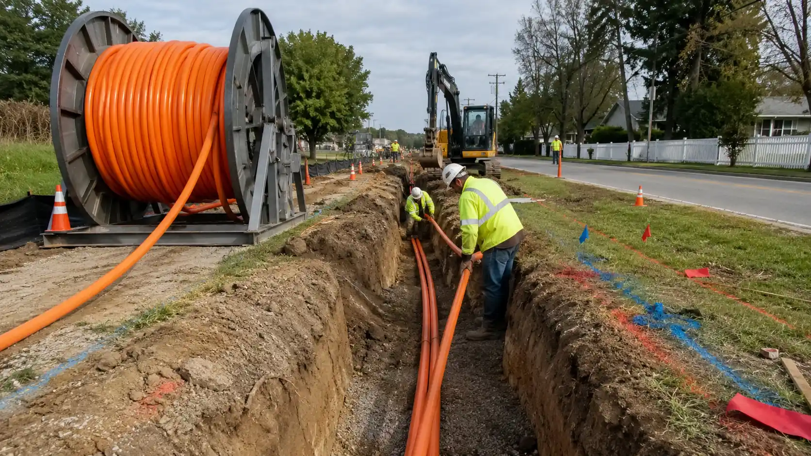
Underground fiber optic cable installation can create a protected, long-life pathway for campus backbones, building-to-building links, telecom routes, industrial networks, and other outside-plant systems. The difficult part is not simply getting cable into the ground. A reliable installation depends on matching the route, pathway, cable construction, pulling or blowing method, access points, safety controls, testing plan, and future maintenance strategy.
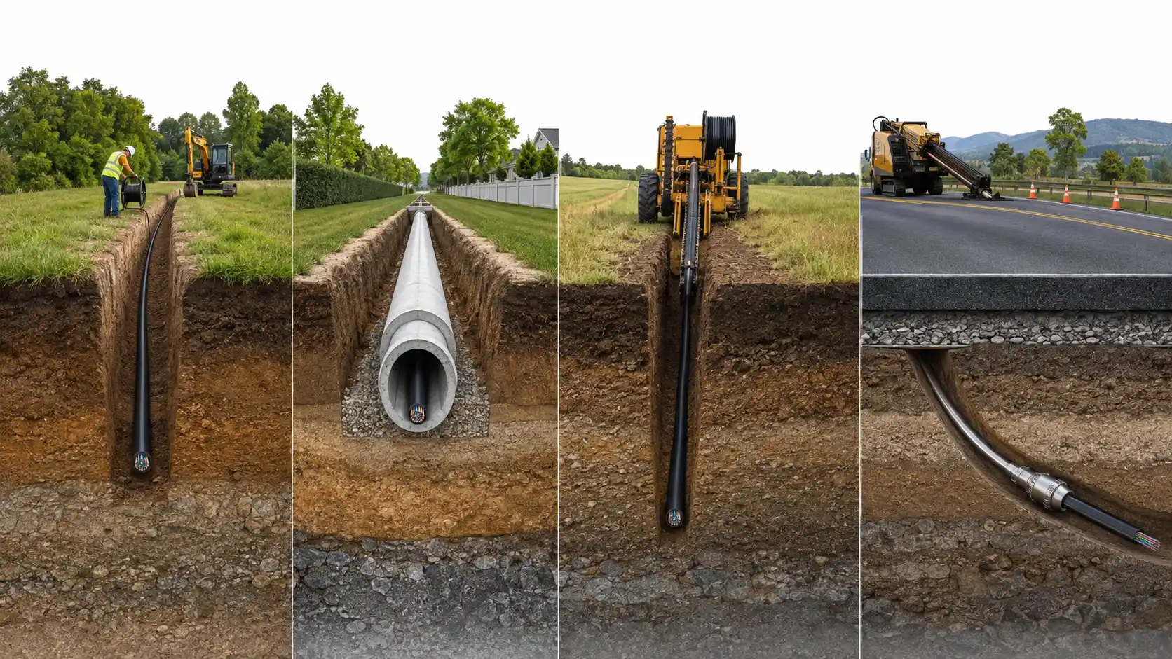
Underground fiber can be installed by direct burial, inside conduit or duct, through open trenching, by cable plowing, or through trenchless methods such as horizontal directional drilling (HDD). The best method depends on surface disruption, soil and rock, road crossings, existing utilities, future expansion, restoration cost, cable replacement expectations, and the cable manufacturer's installation limits.
A practical design often uses more than one method. For example, a route may use direct burial across open ground, conduit at building entrances, and HDD under a road. The goal is not to choose one technique for the entire project; it is to choose the lowest-risk method for each section of the route.
What Is Underground Fiber Optic Cable Installation?
Underground fiber optic cable installation is the placement of outside-plant fiber below grade between network locations. The fiber may be installed directly in soil when the cable is specifically rated for direct burial, or it may be installed inside conduit, duct, or microduct.
That distinction matters. Underground installation describes where the cable is installed. Direct-burial cable describes a cable construction intended for direct contact with the underground environment without continuous conduit protection.
An outdoor label alone does not prove that a cable is suitable for direct burial. Before ordering cable, confirm the manufacturer's environmental rating, moisture protection, tensile limits, minimum bend radius, temperature range, and approved installation method. For a broader overview of environmental categories, see this guide to outdoor fiber optic cable types and ratings.
Which Underground Fiber Installation Method Should You Use?
A useful method-selection rule is to start with the constraint that is hardest or most expensive to change later. On an undeveloped route, that may be trenching cost. On a campus, it may be future cable replacement. At a road crossing, it may be restoration and traffic disruption. In congested utility corridors, it may be safe constructability.
| Route Condition | Method to Favor | Why | Main Watch-Out |
|---|---|---|---|
| Long, open, undeveloped route with low expectation of cable replacement | Direct burial or plowing | Reduces continuous conduit material and can be efficient over suitable terrain | Cable must be rated for the environment; later replacement can require excavation |
| Campus, building-to-building, industrial, or expandable network | Conduit or duct | Provides a reusable pathway for replacement, additional cable, and maintenance access | Requires more route planning, access points, bend control, and pathway construction |
| Road, driveway, pavement, landscaped feature, or sensitive surface crossing | HDD or another engineered trenchless method | Avoids continuous open excavation across the surface | Utility conflicts, bore geometry, soil conditions, entry/exit space, and specialist equipment |
| Long open corridor with suitable soil and few obstructions | Cable plowing | Can install cable or duct with less open excavation than conventional trenching | Rock, buried utilities, abrupt grade changes, and unsuitable cable construction can limit use |
| High-fiber-growth route where incremental installation is expected | Microduct system | Allows compatible microcables to be added through available pathways later | Duct, cable, connectors, installation equipment, and design must be treated as one system |
Direct Burial
Direct burial places a cable specifically designed for the application directly in the ground. It can be attractive for long open routes where future cable additions are unlikely and the ground can be disturbed without excessive restoration cost.
The tradeoff is access. A direct-buried route does not give technicians a reusable continuous pathway, so later replacement may require excavation. Cable construction is therefore critical. Depending on the project, direct-burial cable may use moisture-blocking elements, robust jackets, crush-resistant construction, rodent protection, or armor.
Conduit or Duct
With conduit installation, the pathway is built first and the fiber is pulled, blown, or jetted through it. The most important benefit is lifecycle flexibility. A well-designed duct route can make future cable replacement or capacity growth possible without reopening the entire ground surface.
Conduit does not remove the need for an underground-rated cable. Ducts can contain water, debris, sediment, temperature variation, and mechanical stress. The cable still needs to be approved for the actual environment and installation technique.
Open Trenching
Open trenching provides direct access to the route and can accommodate direct-burial cable, conduit, multiple ducts, warning tape, and other project elements. It works best where continuous surface disturbance is acceptable. Its cost and disruption rise quickly when the route crosses pavement, finished landscaping, traffic areas, or developed sites.
Cable Plowing
Plowing can be efficient across long open corridors when soil and route conditions are suitable. It reduces the length of trench left open at one time, but it is not a substitute for route investigation. Existing utilities, rock, drainage features, cable construction, and required cover still control whether the method is appropriate.
Horizontal Directional Drilling
HDD creates an underground path without opening the full surface route. It is often a strong choice for roads, driveways, waterways, landscaped areas, and other crossings where restoration would be disruptive or expensive.
Use HDD because the crossing justifies it, not because trenchless construction is automatically superior. The bore must be designed around subsurface utilities, soil and rock, bend limits, bore length, entry and exit angles, available work space, and the cable or conduit that will be installed.
How to Choose the Right Underground Fiber Optic Cable
The pathway and the cable should be selected together. Choosing a route first and assuming that any outdoor fiber cable will work in it is a common source of avoidable problems.
Confirm the Environmental and Installation Rating
Before purchase, obtain the manufacturer's data sheet and installation instructions. Confirm:
- whether the cable is rated for outdoor use, underground conduit, or direct burial;
- how the design manages water and moisture;
- the allowable installation temperature and service temperature;
- maximum installation pulling tension and long-term tensile load;
- minimum bend radius during installation and after installation;
- whether pulling, blowing, jetting, or plowing is approved;
- whether special pulling hardware, lubricant, or sealing methods are required.
Armored vs. Non-Armored Fiber
Armor can add mechanical protection against crushing, impact, rodents, and other physical hazards, but it is not automatically required for every underground route. A cable inside a properly designed conduit may have a different risk profile from a cable placed directly in rocky soil. If armor is being considered, compare the actual protection levels and construction options in this armored fiber optic cable guide.
Loose-Tube Construction and Moisture Protection
Outside-plant designs commonly use cable constructions intended to isolate the fibers from environmental and mechanical stress. Rather than choosing a cable because a construction name sounds familiar, verify the exact product's water-blocking system, jacket, strength members, armor if present, and environmental rating.
Also treat splice points and closures as part of the same environmental system. An underground cable can be correctly selected and still fail operationally if a splice enclosure is poorly matched to the location. Where underground or outdoor splicing is planned, review the requirements for an appropriate fiber optic splice closure.
Single-Mode vs. Multimode
Fiber type is a network-design decision, not an excavation decision. Single-mode is normally selected for long outside-plant and interbuilding routes because it supports long reach with appropriate optics, while multimode may fit shorter architectures with compatible equipment. Confirm the link distance, transceivers, bandwidth target, loss budget, and future upgrade plan before ordering cable. For design context, compare single-mode and multimode fiber.
How Deep Should Underground Fiber Optic Cable Be Buried?
There is no universal burial depth for every underground fiber project. Required cover can be controlled by the authority having jurisdiction, road or utility owner, permit conditions, project specifications, direct-burial versus conduit construction, crossings, frost, soil and rock, agricultural activity, landscaping, and proximity to other utilities.
Use published numbers only as examples of how requirements vary, not as a substitute for the approved design. For example, the U.S. Department of Agriculture Rural Utilities Service Form 515 includes a buried filled fiber optic cable assembly specification with a 24 in. (61 cm) minimum in soil for that particular BFO specification, while also allowing the engineer to require greater depth. That number is not a general U.S. rule and should not be copied into another project without checking the controlling requirements. See the USDA RUS Form 515 for the original specification.
Before finalizing depth, verify the exact requirement for:
- private property versus public right-of-way;
- road, driveway, rail, drainage, or water crossings;
- direct-buried cable versus conduit;
- separation from power, gas, water, and other communications facilities;
- areas exposed to grading, agricultural equipment, landscaping, or future excavation;
- rock, frost, erosion, or drainage conditions;
- local utility-owner and permit requirements.
If a route passes under pavement or an area subject to heavy equipment, the engineering solution may involve greater cover, casing, concrete protection, a different conduit system, or an engineered crossing. The approved project documents should control.
Construction Safety Comes Before Cable Placement
Underground fiber work combines telecommunications installation with excavation, traffic, machinery, utility, and sometimes confined-space hazards. A fiber installation guide is not a substitute for a project safety plan or competent-person requirements.
Locate Existing Underground Utilities
In the United States, OSHA 29 CFR 1926.651 requires the estimated location of underground installations that may be encountered to be determined before opening an excavation and requires utility companies or owners to be contacted as specified by the standard. Review the original OSHA excavation requirements and follow the applicable state, local, owner, and utility-location process.
Do not rely only on old drawings. Markouts, records, potholing or other approved verification methods, and field conditions need to be reconciled before excavation or boring approaches an existing facility.
Control Excavation and Access Hazards
Trench stability, protective systems, water accumulation, access and egress, equipment near excavations, traffic exposure, and hazardous atmospheres may require specific controls. The details depend on the excavation and the governing safety rules.
Treat Manholes and Vaults as Potential Confined Spaces
Communication manholes and utility vaults can fall within OSHA's construction confined-space rules depending on the work and conditions. OSHA specifically lists communication and other utility manholes among locations where confined spaces may occur. Where applicable, use the required evaluation, entry controls, testing, training, and rescue planning described in OSHA 1926 Subpart AA.
Before Installation: Planning and Site Preparation
1. Survey the Entire Route
Map endpoints, building entrances, elevation changes, pavement, drainage, existing handholes or manholes, utility crossings, major bends, proposed splice points, and future branch locations. The shortest route on a drawing is not always the safest or easiest route to build.
2. Decide Where Access and Slack Are Needed
Plan handholes, vaults, splice locations, and service loops before construction. Ask where a technician will need to access the cable five or ten years later for a splice, repair, branch, or replacement. Access points that are convenient during construction but inaccessible during maintenance create long-term cost.
3. Check Cable Length and Reel Logistics
Route length is only the starting point. Include entry lengths, service loops, splice allowances, planned slack, and installation handling. Then confirm that the reel can physically reach a safe setup location and pay off in the correct direction.
A simple field reality often changes the design: a route can be clear on paper but difficult to install because there is no safe place for the reel, puller, compressor, or intermediate handling crew.
4. Inspect and Baseline-Test the Cable
Inspect reels on delivery and document visible damage. On important links, a pre-installation optical baseline can provide evidence of the cable's condition before it enters the pathway. If final test results are abnormal, that baseline helps separate shipping or manufacturing issues from installation damage.
Underground Fiber Optic Cable Installation: Step by Step
- Finalize the route and installation method. Mark where the project transitions between trenching, direct burial, conduit, plowing, and trenchless sections. Resolve permits and owner requirements before construction starts.
- Locate utilities and establish safety controls. Complete the required utility-location process, verify critical conflicts as required by the project, and implement excavation, traffic, and confined-space controls before crews enter the work area.
- Build the trench, bore, or conduit pathway. Follow the approved design. Avoid unnecessary bends and abrupt direction changes. Place access points where they support both installation and future maintenance.
- Inspect, clean, and prove conduit. Before cable placement, verify continuity and check for crushed duct, debris, water, obstructions, unexpected bends, and the availability of an appropriate pull line. Discovering a blockage before the cable enters the duct is far cheaper than stopping a loaded pull midway.
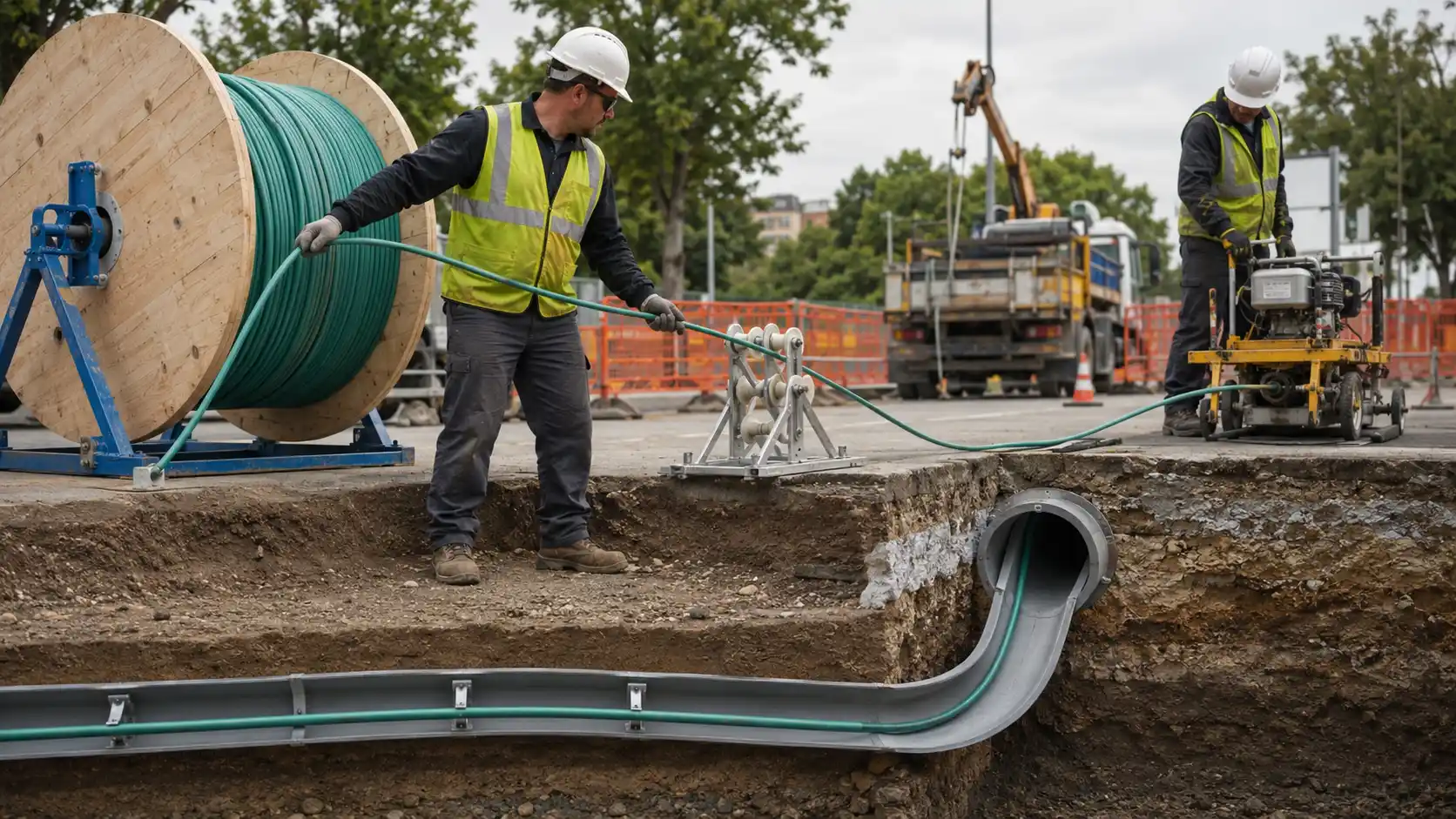
- Set up the cable reel correctly. Support the reel on suitable equipment and orient it so the cable pays off smoothly. Do not drag cable sideways from a stationary reel or allow uncontrolled loops, kinks, or twists to form.
- Select pulling, blowing, or jetting deliberately. Match the technique to the cable, duct, route length, bend geometry, equipment, and manufacturer's instructions. Do not switch methods in the field simply because a pull becomes difficult.
- Control bend radius, pulling tension, and sidewall pressure. Use the product's published limits and suitable installation hardware. If resistance rises unexpectedly, stop and diagnose the pathway rather than applying more force.
- Store service slack without creating tight coils. Provide the planned maintenance slack at handholes, vaults, entrances, and splice points while maintaining the cable's installed bend-radius requirement.
- Splice and terminate the fiber. Follow the network design, protect outdoor splices with suitable closures, maintain fiber organization, and label cables, buffer tubes, fibers, trays, and termination points.
- Seal pathways and secure access points. Seal duct openings with systems appropriate to the pathway and cable so water, dirt, and pests are less likely to enter. Secure handholes, manholes, vaults, closures, and building entrances.
- Backfill and restore the site. Protect the cable or duct from sharp or damaging material, follow the project backfill and compaction requirements, and restore pavement, landscaping, and other surfaces as specified.
- Test and document the finished link. Perform the required optical tests, save results, update the final route, record splice and access locations, and capture changes made during construction before the project is accepted.
Pulling vs. Blowing Fiber Through Conduit
Pulling and air-assisted installation can both be effective, but they apply force differently. The right choice depends on the specific route rather than a generic distance rule.
When Pulling Makes Sense
Pulling is often practical for shorter or moderate routes with controlled geometry, suitable conduit, an appropriate pull line, and equipment that can keep cable tension within limits. Friction, bends, conduit fill, and sidewall pressure matter more as the route becomes longer or more complex.
A 100 ft straight building entrance is a very different pulling problem from a 1,000 ft campus duct with multiple sweep bends, even when the same cable is used. The longer route may require a formal pulling calculation, intermediate access, different equipment, or a different installation technique.
Corning's engineering note on pulling fiber optic cable in conduit instructs installers to follow the cable manufacturer's maximum pulling tension and minimum bend radius and to consider bend radius, tension, jamming, and fill ratio before a conduit pull.
When Blowing or Jetting Makes Sense
Air-assisted installation can be advantageous with compatible cable and duct systems, especially when the route would otherwise concentrate excessive pulling force at the cable end. Successful blowing depends on duct condition, cable-to-duct compatibility, route geometry, air supply, equipment setup, and the manufacturer's method.
There is no reliable universal answer to "How far can fiber be blown?" A straight, clean, correctly sized duct can behave very differently from a route with bends, elevation changes, poor joints, water, or contamination. Use the cable, duct, and equipment manufacturer's planning data for the actual route.
How to Protect Fiber During Installation
Stop When Pulling Force Rises Unexpectedly
A stalled cable is a diagnostic signal, not permission to increase force. A blockage, tight bend, damaged duct, cable twist, or poor transition may be causing the resistance. Continuing can damage the cable even when the jacket still looks intact.
Protect Every Bend, Not Just the Final Route
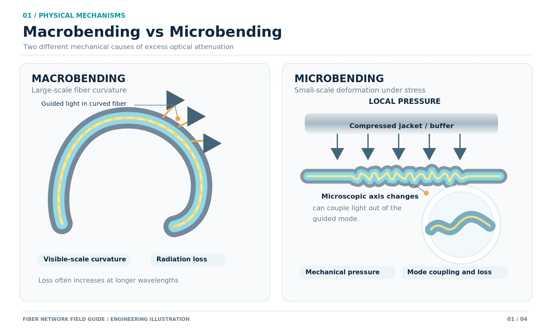
Bend-radius limits apply at conduit mouths, handholes, rollers, sheaves, reel setups, pulling equipment, and building entrances during installation. The most damaging bend can occur temporarily while the cable is being handled rather than in its final position.
Prevent Twist and Poor Reel Handling
Use suitable pulling swivels and cable-handling practices where specified. Long sections that must be backfed should be stored using methods that prevent twist and kinking rather than piled into uncontrolled coils.
Protect Pre-Terminated Assemblies
Connectors and breakout components can be larger and more fragile than the cable body. Use the manufacturer's pulling eye or protective system if the assembly is designed to be installed pre-terminated. Never assume that a connector can tolerate the same pulling load as the cable strength members.
Testing and Acceptance of an Underground Fiber Link
Testing should answer two different questions: Does the complete link meet its loss requirement? and Are there localized events or installation problems that need investigation? The project specification should define the required acceptance tests.

Pre-Installation Baseline
For critical or high-value cable, baseline testing before installation can establish the delivered condition. Save the records with the reel or cable identifier so they can be compared with final results.
End-to-End Optical Loss Testing
End-to-end loss testing verifies whether the installed link is within its allowable loss budget. Use the specified wavelengths, reference method, launch conditions, and test direction required by the project or applicable standard. A general overview of instruments and procedures is available in this guide to fiber optic testing equipment and guidelines.
OTDR Characterization
An optical time-domain reflectometer can help locate and characterize events along the link, including connectors, splices, bends, and breaks. It is particularly useful for troubleshooting and for creating a baseline trace that can be compared with future measurements.
For an introduction to the instrument, see what an OTDR is and how it is used. Fluke Networks also explains that OTDR testing can identify events such as connections, bends, splices, cracks, and breaks and can support documented troubleshooting; see its OTDR guide.
Do not treat OTDR as a universal replacement for end-to-end loss testing. The acceptance plan should specify which tests are required and what pass/fail criteria apply.
Inspect and Clean Connector End Faces
A buried cable can be mechanically perfect and still produce poor link performance because of contaminated or damaged connectors. Inspect and clean connector end faces using the approved procedure before final optical testing.
Save the Records
At minimum, associate test files with cable and fiber identifiers, endpoints, splice locations, and the final route. The value of a baseline is lost if technicians cannot determine which fiber a trace belongs to years later.
Common Underground Fiber Installation Mistakes
- Using an outdoor cable that is not approved for the actual underground environment. Confirm the exact product rating rather than relying on a general "outdoor" label.
- Copying a burial depth from another project. Verify the controlling permit, owner specification, and local requirements.
- Beginning excavation before utilities are properly located. Treat utility verification as a construction prerequisite.
- Choosing a method only by first cost. A cheaper direct-burial route can become expensive if frequent future replacement is expected.
- Designing too many bends into conduit. Every bend increases installation difficulty and can reduce future pathway usability.
- Starting a pull through dirty or unproven duct. Clean and prove the pathway first.
- Increasing pulling force when the cable stops. Stop, diagnose, and correct the cause.
- Leaving no planned service slack. Future splicing and repair should not depend on accidental leftover cable.
- Testing only after installation on a critical link. A pre-installation baseline can make troubleshooting much faster.
- Finishing construction without accurate as-built records. Record what was actually installed, not only what the original drawing proposed.
Frequently Asked Questions
Can fiber optic cable be buried without conduit?
Yes, if the cable is specifically rated for direct burial and the project design allows it. An outdoor or armored cable is not automatically a direct-burial cable. Confirm the manufacturer's rating and the local or owner requirements for the route.
Does underground fiber always need to be armored?
No. Armor is a risk-control feature, not a universal requirement. Direct-buried routes, rodent-prone areas, rocky soil, or locations exposed to crushing may justify additional mechanical protection. A suitable cable inside a well-designed conduit may not need the same construction.
Can water damage fiber inside conduit?
Underground ducts should not be assumed to remain dry. Water and moisture can affect cable jackets, closures, connectors, metallic components, and pathway conditions, and freezing water can create mechanical stress. Use cable and sealing systems rated for the actual underground environment.
Can you pull fiber through existing conduit?
Often yes, but first verify ownership, available space, conduit condition, bend geometry, existing cable occupancy, pull-line condition, and whether the new cable can be installed without exceeding tension, bend, fill, or separation requirements. Prove and clean the pathway before installation.
How far can fiber be blown through conduit?
There is no universal maximum distance. Achievable distance depends on the cable and duct dimensions, friction, duct cleanliness, bends, elevation changes, joints, air equipment, and installation procedure. Use the cable, duct, and blowing-equipment manufacturer's planning data for the actual route.
Should underground fiber be tested before installation?
For important links, pre-installation baseline testing is often useful because it documents the cable's condition before placement. Final acceptance testing is still required after installation according to the project specification.
Is direct burial better than conduit?
Neither is universally better. Direct burial can be efficient on open routes where future cable changes are unlikely. Conduit is usually more attractive where replaceability, expansion, pathway reuse, or additional physical separation is valuable. Many projects use both.
Final Thoughts
Reliable underground fiber installation comes from a sequence of decisions rather than one construction technique. Define the route, identify the hardest constraints, select the pathway and cable as a system, plan access and future maintenance, control installation forces, and test before acceptance.
Three rules prevent a large share of avoidable mistakes: do not assume that every outdoor cable can be buried directly, do not copy a universal burial depth from the internet, and do not exceed the cable manufacturer's installation limits to force a difficult pull to completion.
If those decisions are resolved before the reel reaches the site, the installation crew has a much better chance of delivering a link that is not only working on day one, but also serviceable years later.