Choosing a single-mode SFP+ module by the distance printed on its label is not enough. A reliable 10 Gigabit Ethernet link must remain inside both sides of the receiver window: the signal must be strong enough to exceed receiver sensitivity, but not so strong that it exceeds the maximum receiver input.
This guide compares 10GBASE-LR, 10GBASE-ER, and 10GBASE-ZR by wavelength, reach, transmitter and receiver power, optical budget, attenuation, chromatic dispersion, power consumption, temperature range, DOM, and host compatibility. Readers who need a broader introduction can begin with what an SFP module does.

Quick Answer: LR, ER, or ZR?
- Choose LR first for a normal duplex single-mode link that fits within its measured loss budget and approximately 10 km reach.
- Evaluate ER for longer links approaching 40 km, with a complete loss calculation, receiver-overload check, and any manufacturer-required attenuation.
- Evaluate ZR for approximately 70 to 80 km only when the exact vendor implementation, host support, optical power window, dispersion tolerance, and remote-end interoperability are documented.
The correct choice is normally the shortest reach class that safely covers the measured path. Installing a higher-power ER or ZR module on a short, low-loss route can overload the receiver.
Clarify the Naming Before Comparing Specifications
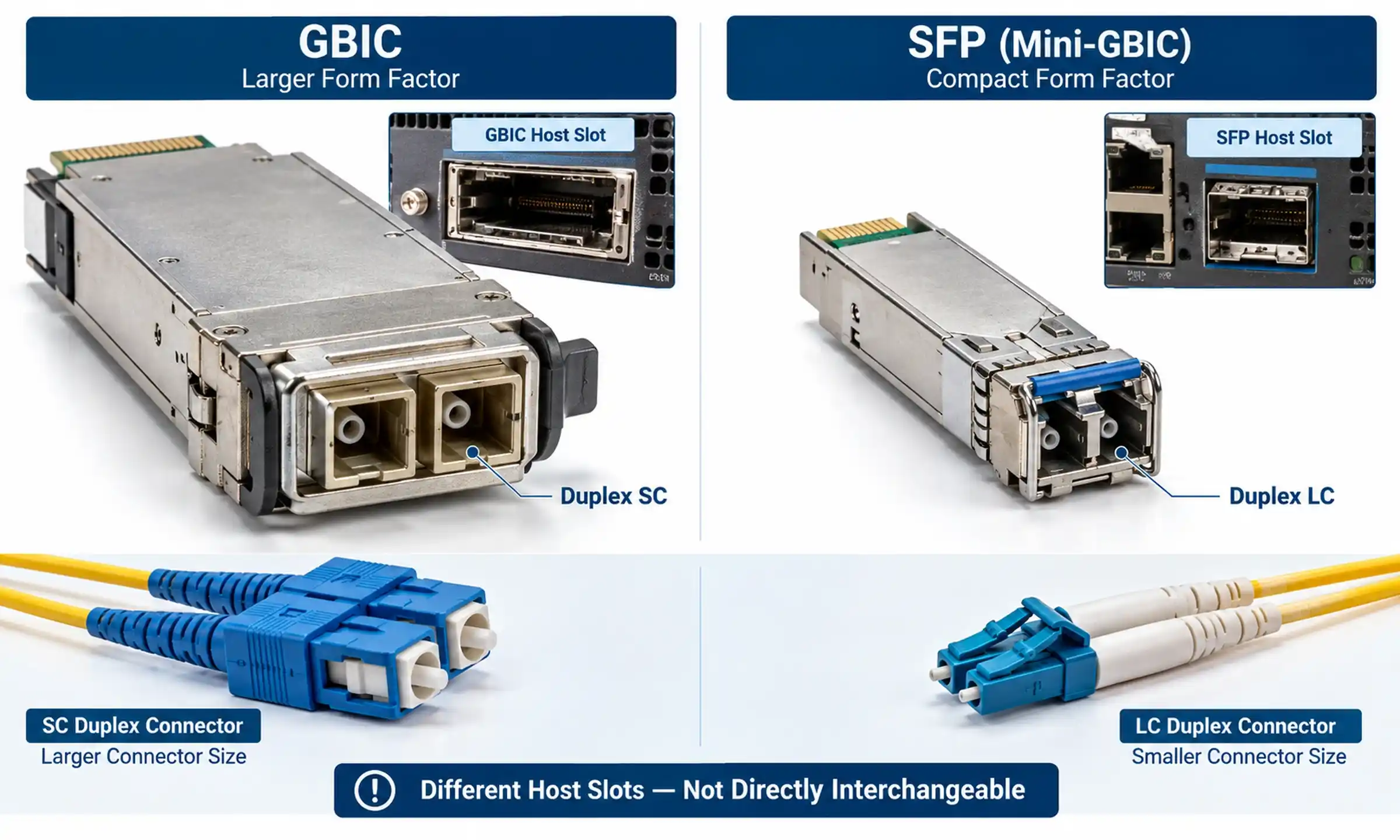
SFP and SFP+ have similar physical dimensions, but they do not represent the same host electrical interface or data rate. FOCC's guide to SFP vs SFP+ compatibility explains why physical fit alone does not prove that a module will operate in a port.
For 1 Gigabit Ethernet, 1000BASE-LX is an IEEE interface name. EX and ZX are commonly used vendor or market names for longer-reach 1G optics, so their actual Tx/Rx specifications must be checked by part number.
This article uses LR, ER, and ZR in the 10G SFP+ context:
- 10GBASE-LR: approximately 10 km over single-mode fiber.
- 10GBASE-ER: approximately 40 km over single-mode fiber.
- 10GBASE-ZR: commonly approximately 70 to 80 km, but often implemented as a vendor-defined interface.
The original IEEE 802.3ae 10Gb/s Ethernet amendment introduced the 10GBASE-R optical family that includes LR and ER. At 10G, ZR is widely used as a market name, but its optical parameters are not one universal IEEE interface.
Four Sources of a Module Specification
| Specification source | What it defines | How to use it |
|---|---|---|
| IEEE Ethernet standard | Standardized Ethernet PHY behavior and optical-interface requirements for defined interfaces such as LR and ER | Use it to identify the standardized interface and its compliance boundary |
| SFP+ multisource specifications | Form factor, host electrical interface, memory map, management, and monitoring conventions | Use it to understand the module-host interface and DOM data structure |
| Transceiver vendor data sheet | Exact wavelength, Tx/Rx range, dispersion, temperature, power, FEC behavior, and attenuator rules | Use the exact part number at both endpoints |
| Host compatibility matrix | Supported switch, router, line card, software release, and module coding | Confirm that the host accepts and operates the specific optic |
FOCC's fiber optic transceiver range shows common product families, but the final design must be based on the exact local and remote modules and the host documentation.
LR vs ER vs ZR Reference Specifications
The following table uses Cisco SFP-10G-LR, SFP-10G-ER, and SFP-10G-ZR as a clearly identified reference example. These values must not be treated as universal specifications for every compatible or third-party module. Verify the current data sheet for the exact part number.
| Parameter | Cisco 10GBASE-LR reference | Cisco 10GBASE-ER reference | Cisco 10GBASE-ZR reference |
|---|---|---|---|
| Typical reach category | 10 km | 40 km | 80 km |
| Fiber | G.652 single-mode fiber | G.652 single-mode fiber | G.652 single-mode fiber |
| Connector | Duplex LC PC/UPC | Duplex LC PC/UPC | Duplex LC PC/UPC |
| Wavelength range | 1260 to 1355 nm | 1530 to 1565 nm | 1530 to 1565 nm |
| Minimum Tx power | -8.2 dBm | -4.7 dBm | 0 dBm |
| Maximum Tx power | 0.5 dBm | 4.0 dBm | 4.0 dBm |
| Receiver sensitivity | -14.4 dBm | -15.8 dBm | -24 dBm for the cited non-FEC 10GE reference |
| Maximum receiver input | 0.5 dBm | -1 dBm | -7 dBm receiver-overload reference |
| Calculated worst-case budget | 6.2 dB | 11.1 dB | 24 dB |
| Minimum cabling distance in the cited Cisco table | 2 m | 2 m, with Cisco attenuation rules for short links | Vendor-specific short-link attenuation rules |
| Standards status | IEEE-defined Ethernet interface | IEEE-defined Ethernet interface | Cisco-specific implementation in the cited data sheet |
| Maximum chromatic dispersion in the cited module data | Use the exact module/standard limit | Use the exact module/engineered-link limit | 1600 ps/nm for the cited Cisco commercial ZR reference |
| Maximum power consumption in the cited commercial module family | 1 W | 1.5 W | 1.5 W |
| Commercial operating-temperature range | 0 to 70°C | 0 to 70°C | 0 to 70°C |
| DOM | Supported on the cited Cisco module family | Supported on the cited Cisco module family | Supported on the cited Cisco module family |
The official Cisco 10GBASE SFP+ module data sheet is the source for the reference values above. Its stated power ranges also show why the maximum-distance label cannot replace a complete power-window calculation.
10GBASE-LR: The Normal Starting Point
10GBASE-LR commonly operates around 1310 nm and is intended for approximately 10 km over suitable single-mode fiber. It is normally the first option evaluated for building-to-building, campus, enterprise dark-fiber, and short metro links.
The cited Cisco LR values produce a 6.2 dB worst-case budget:
-8.2 dBm minimum Tx - (-14.4 dBm receiver sensitivity) = 6.2 dB
The complete channel loss, including the chosen engineering margin, must remain below that budget. The maximum expected receive power must also remain below 0.5 dBm for this specific reference module.
FOCC's 10GBASE-LR SFP+ product page can be used as a product-selection starting point. The module data sheet and host compatibility matrix remain the approval documents.
10GBASE-ER: Longer Reach Becomes an Engineered Link
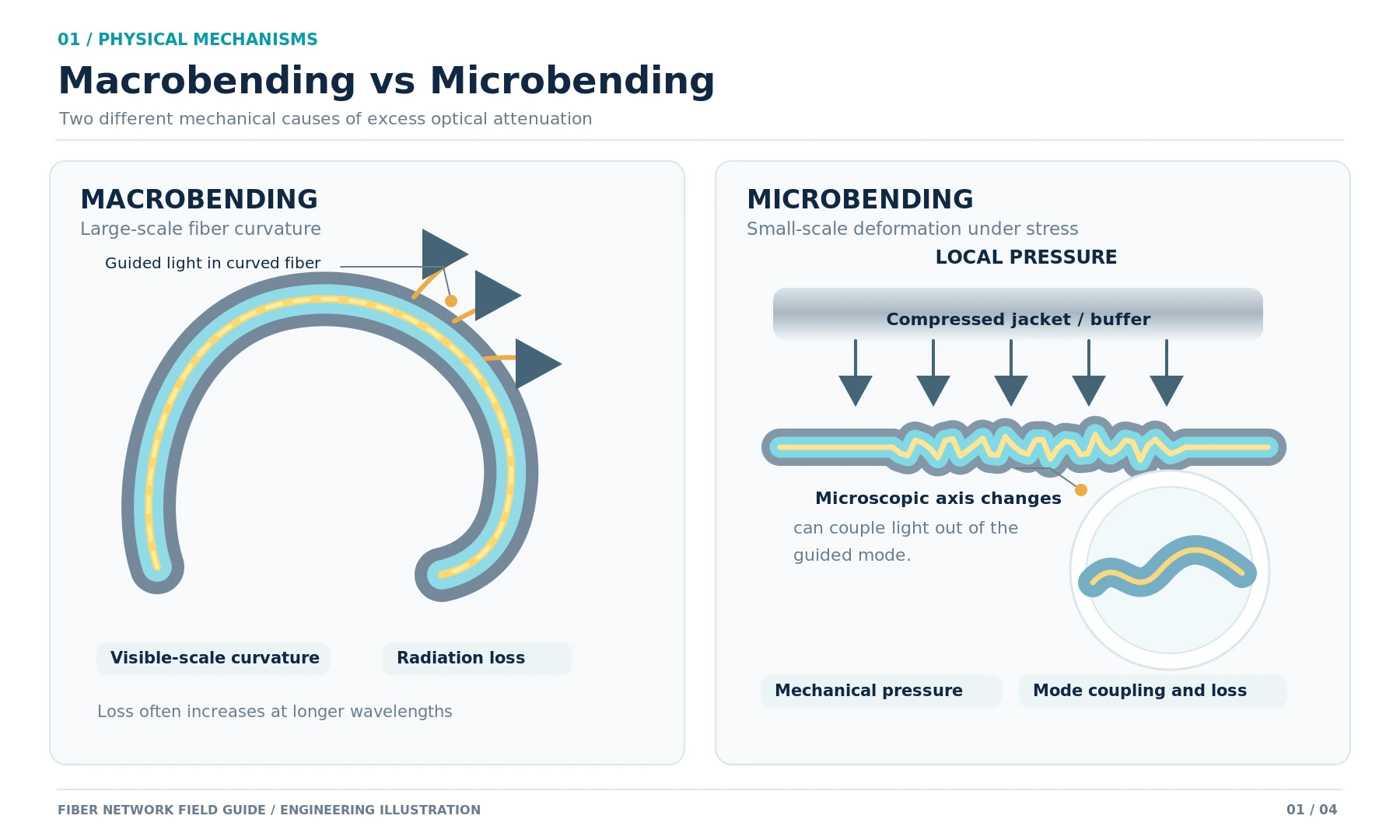
10GBASE-ER commonly operates in the 1550 nm region and is used for links approaching 40 km. The lower fiber attenuation near 1550 nm helps, but connectors, splices, patch panels, bends, repairs, uncertainty, aging margin, and chromatic dispersion still consume system margin.
The cited Cisco ER values produce an 11.1 dB worst-case budget:
-4.7 dBm minimum Tx - (-15.8 dBm receiver sensitivity) = 11.1 dB
Cisco identifies links beyond 30 km as engineered links and requires a 5 dB fixed 1550 nm attenuator for its cited ER modules on links below 20 km. That is a Cisco product rule, not a universal instruction for every ER module.
Review the exact specification before selecting a 10GBASE-ER SFP+. A 40 km label does not prove that a high-loss 35 km route fits the budget, and it does not prove that a short route is safe from receiver overload.
10GBASE-ZR: Verify the Vendor Implementation
10GBASE-ZR modules commonly operate near 1550 nm and are marketed for approximately 70 to 80 km. At 10G, ZR is not one universally identical IEEE optical interface. Two modules with the same "80 km ZR" label can differ in receiver window, FEC behavior, dispersion tolerance, host requirements, power, and temperature rating.
For the cited Cisco commercial ZR reference:
- Tx range is 0 to 4.0 dBm.
- Receiver sensitivity is -24 dBm for the cited non-FEC 10GE condition.
- Receiver overload is -7 dBm.
- Maximum chromatic dispersion is 1600 ps/nm.
- The interface is built to Cisco specifications rather than defined as a 10G Ethernet ZR standard.
Cisco also specifies fixed attenuation by distance for this particular ZR family: 15 dB below 5 km, 10 dB from 5 to 25 km, and 5 dB from 25 to 45 km. These values illustrate the seriousness of short-link overload, but they must not be copied to a different vendor's module without checking its instructions.
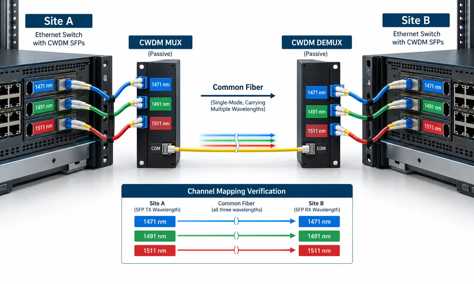
Before selecting a 10GBASE-ZR SFP+, compare both endpoints field by field. When a long route includes passive wavelength filters, amplification, or multiple services, review whether a long-distance DWDM architecture is more appropriate than a stand-alone gray ZR link.
Calculate Both the Lower and Upper Power Limits

1. Calculate the Available Optical Budget
Available budget = minimum transmitter power - receiver sensitivity
Use worst-case values from the exact data sheet. Do not use typical transmitter power when the minimum is available.
2. Calculate the Planned Channel Loss
Planned channel loss = fiber loss + connector loss + splice loss + passive-device loss + engineering margin
Use measured insertion loss when available. Design allowances must be identified separately from field measurements.
3. Calculate the Remaining Margin
Remaining margin = available budget - planned channel loss
A zero-margin design can pass on commissioning day and fail after contamination, repair, temperature change, or component aging.
4. Check Receiver Overload
Maximum expected Rx = maximum transmitter power - minimum possible path loss
The result must remain below the module's maximum receiver input. Juniper's official fiber-optic power-budget planning guide similarly recommends using transmitter and receiver specifications to calculate power budget and margin.
Worked 35 km ER Example
The following is an illustrative engineering exercise, not a claim about an installed FOCC or customer link. Replace every allowance with project measurements, contract limits, and the exact module specification.
| Loss item | Illustrative assumption | Calculated loss |
|---|---|---|
| 35 km fiber at 1550 nm | 0.25 dB/km | 8.75 dB |
| Four mated connector pairs | 0.30 dB per pair | 1.20 dB |
| Eight fusion splices | 0.10 dB per splice | 0.80 dB |
| Engineering and repair margin | 1.00 dB | 1.00 dB |
| Total planned loss | 11.75 dB |
Using the cited Cisco ER reference, the available budget is 11.1 dB. Under these illustrative assumptions, the planned loss is 0.65 dB greater than the available budget:
11.1 dB budget - 11.75 dB planned loss = -0.65 dB margin
This design should not be approved from the 40 km label alone. The next step is not automatically to install ZR. The engineer should first replace assumptions with measured loss, inspect connectors, verify splice records, confirm the actual ER module limits, review dispersion, and decide whether the route or architecture needs to change.

The overload side should also be checked. With a maximum ER Tx of 4.0 dBm and the lowest credible path loss, the calculated receive power must stay below the -1 dBm maximum input of the cited module. Apply any vendor-required attenuation even when the loss-budget calculation appears acceptable.
How to Decide Whether an Attenuator Is Required
- Find the exact module's maximum Tx power and maximum receiver input.
- Measure or conservatively estimate the minimum path loss, not only the expected average loss.
- Calculate the maximum expected receive power.
- Compare the result with the receiver's maximum input and any manufacturer-defined minimum-distance rule.
- Calculate the attenuation required to create safe headroom.
- Select the correct wavelength, connector, polish, and fixed value.
- Measure both endpoints again after installation and record the new baseline.
FOCC's guide to optical attenuators explains their role in signal control. Use the transceiver manufacturer's rules rather than choosing a value from a generic distance table.
Fiber, Connector, and Polarity Requirements
OS2 is a cabling category, while ITU-T G.652 describes single-mode fiber characteristics. They are related but not interchangeable labels. The actual installed fiber, cable construction, attenuation, repairs, and dispersion must be verified. FOCC's comparison of OS1 vs OS2 single-mode fiber provides additional cabling context.
Modern duplex LR, ER, and ZR links normally use two fibers and duplex LC PC/UPC interfaces. Suitable OS2 single-mode patch cords are available for equipment connections, including an LC UPC duplex patch cord.
Do not connect an LC/APC patch cord directly to a PC/UPC transceiver interface unless the module documentation explicitly supports it. The angled and non-angled end faces do not mate correctly and can create high loss, reflection, and unstable performance. FOCC's article on SFP compatibility with APC and UPC explains this issue in more detail.
For a duplex link, local Tx must connect to remote Rx and local Rx to remote Tx. Inspect, clean, and reinspect accessible end faces before replacing a module or moving to a longer-reach optic.
Host and Remote-Module Compatibility
A module can be optically correct and still be rejected or misoperated by the host. Confirm:
- The port supports 10G SFP+ operation and the intended protocol.
- The exact switch, router, line card, and software release support the part number.
- The host accepts the module coding and exposes required DOM fields.
- The port power and thermal limits support the selected optic.
- The temperature rating matches the cabinet or data-center environment.
- Both endpoints use compatible line rates, wavelengths, receiver windows, and FEC behavior.
- ZR interoperability is documented rather than inferred from the distance label.
Cisco provides an official transceiver compatibility matrix, and Juniper provides a hardware compatibility tool. Use the current tool for the actual platform rather than relying on a generic compatible-module claim.
Third-Party Module Acceptance
When an approved third-party module is used, the acceptance plan should include more than initial link-up:
- Inventory and EEPROM recognition after insertion.
- DOM visibility and threshold reporting.
- Stable operation after a cold or warm reboot.
- Interface error counters under representative traffic.
- Optical interoperability with the remote module.
- Temperature stability in the intended environment.
- Revalidation after a planned switch software upgrade.
- Rollback to an approved known-good optic if acceptance fails.
Use DOM as Evidence, Not as the Entire Test
Digital Optical Monitoring can expose Tx power, Rx power, temperature, supply voltage, laser bias current, and alarm or warning thresholds. The official SNIA SFF-8472 specification defines the management interface used by SFP+ modules for monitoring and control.
| Record field | Endpoint A | Endpoint B | Acceptance note |
|---|---|---|---|
| Module part number | Record actual value | Record actual value | Must match approved design and host support |
| Tx power | Record actual dBm | Record actual dBm | Compare with each module's data-sheet range |
| Rx power | Record actual dBm | Record actual dBm | Must remain above sensitivity and below maximum input |
| Temperature | Record actual value | Record actual value | Compare with rating and operating environment |
| Laser bias current | Record actual value | Record actual value | Use as a baseline and trend indicator |
| Supply voltage | Record actual value | Record actual value | Check against module thresholds |
| Alarm or warning status | Record status | Record status | No unexplained active alarms at acceptance |
| Date and traffic condition | Record context | Record context | Required for future comparison |
DOM does not directly prove end-to-end insertion loss, connector quality, reflection, dispersion, error-free operation, VLAN configuration, or application performance.
Acceptance-Test Evidence
| Evidence | What it proves | What it does not prove |
|---|---|---|
| Module inventory and host status | The host recognizes the optic and expected line rate | That the optical path has adequate margin |
| DOM at both endpoints | Real-time module readings and threshold status | Calibrated end-to-end channel loss |
| Light source and power meter | End-to-end insertion loss at the test wavelength | The location of individual events |
| OTDR | Distance and location of reflective or loss events | Complete bidirectional insertion-loss acceptance by itself |
| Interface counters and traffic test | Operational stability and error behavior under traffic | Long-term reliability without monitoring |
FOCC's procedures for fiber optic power-meter testing and testing fiber optic cables by OTDR explain the two complementary test methods. When module recognition, DOM, or link status is unclear, follow the site's guide to troubleshoot a transceiver and switch port.

Common Selection Mistakes
| Mistake | Why it fails | Better approach |
|---|---|---|
| Choosing only by 10, 40, or 80 km label | Distance does not prove the power window, dispersion, or margin | Calculate both budget and overload using the exact data sheets |
| Buying ZR because it appears safest | High launch power can overload a short link, and ZR may be vendor-specific | Use the shortest reach class that safely covers the engineered path |
| Applying Cisco attenuation rules to every vendor | Tx/Rx ranges and minimum-distance rules differ | Use the exact module manufacturer's instructions |
| Checking sensitivity but not maximum input | A strong signal can be as invalid as a weak signal | Verify both sides of the receiver window |
| Treating OS2 as proof of reach | The label does not show actual loss, splices, repairs, or dispersion | Measure and document the installed path |
| Mixing APC with PC/UPC transceiver interfaces | The end-face geometries do not mate correctly | Use the connector polish required by the module |
| Assuming two ZR modules interoperate | Vendor optical, FEC, host, and thermal requirements can differ | Compare both part numbers and require documented interoperability |
| Using DOM as the only acceptance test | DOM is a module reading, not a full channel certification | Combine DOM, insertion-loss testing, OTDR where appropriate, counters, and traffic |
FAQ
Q: Can a 10G ER module be used on a 10 km link?
A: Possibly, but the exact module may require attenuation. Check maximum Tx power, minimum path loss, maximum receiver input, and the manufacturer's minimum-distance rule. LR is normally simpler when it covers the route.
Q: Does an 80 km ZR module always reach 80 km?
A: No. The route must fit the module's loss, receiver, dispersion, FEC, temperature, host, and interoperability requirements with adequate margin.
Q: Can ZR modules from different vendors be connected?
A: Do not assume so. Verify the exact wavelength range, Tx/Rx power, line rate, dispersion, FEC behavior, coding, and documented optical interoperability.
Q: What is the difference between receiver sensitivity and receiver overload?
A: Receiver sensitivity is the weakest supported input under stated conditions. Receiver overload or maximum input is the strongest supported operating input. A valid link must stay between them.
Q: Does DOM replace a calibrated power-meter test?
A: No. DOM reports the module's internal readings. A calibrated light source and power meter measures end-to-end insertion loss, while an OTDR helps locate events.
Final Selection Checklist
- The service is confirmed as 10 Gigabit Ethernet over a supported SFP+ port.
- LR, ER, or ZR is selected from measured route requirements rather than distance label alone.
- Both endpoint part numbers and host software support are documented.
- Minimum Tx, maximum Tx, receiver sensitivity, and maximum receiver input are recorded.
- The complete channel loss and engineering margin fit the available budget.
- The maximum expected receive power is below the receiver limit.
- Any manufacturer-required attenuator is specified and measured after installation.
- Fiber type, connector polish, duplex polarity, and end-face cleanliness are verified.
- Chromatic dispersion and any FEC requirement are acceptable for long ER or ZR links.
- Power consumption and temperature rating fit the host and environment.
- DOM baselines are recorded at both ends.
- Insertion loss, OTDR where appropriate, interface counters, and traffic acceptance are complete.
- Rollback optics and the previous configuration remain available until acceptance.
The best single-mode SFP+ is not the module with the longest advertised reach. It is the supported LR, ER, or ZR implementation that keeps the measured path inside its complete optical and operational limits with enough margin for real network conditions.
summarize
This article compares 10G single-mode SFP+ LR, ER, and ZR modules by reach, wavelength, optical power, receiver limits, dispersion, compatibility, and testing requirements. It explains that module selection should be based on the measured optical budget and receiver power window-not distance labels alone-with LR suited to shorter links, ER to engineered medium-distance links, and ZR to vendor-specific long-distance applications.