A fiber optic loopback is a small passive device that turns an optical port back on itself, sending the transmit (TX) signal straight into the receive (RX) side so the equipment can test its own optics with no remote device at the far end. It is one of the quickest ways to answer a single question on site: is this transceiver or port actually transmitting and receiving, or does the fault lie somewhere down the link?
This guide explains what a loopback does, the LC, SC and MPO/MTP types, the 8/12/24-fiber MPO configurations that trip people up most often, how to pick the right one, the faults that produce misleading results, and where loopback testing ends and tools like OTDR and BERT begin.
What Is a Fiber Optic Loopback, and Why It Matters
A fiber optic loopback, also called a loopback plug, loopback module or loopback adapter, is a passive optical component that connects the transmit side of an interface back to its receive side. When the device fires light out of its transmitter, the loopback returns that light to its receiver, closing the optical path locally. No electronics, no power, no second device.
That simple trick is valuable because it isolates the local interface from everything else. A loopback lets a technician confirm:
- Whether an optical transceiver can transmit and receive on its own.
- Whether a switch, router or line-card port comes up under a local diagnostic.
- Whether the equipment even recognizes an inserted module.
- Whether a local optical check passes before the port is patched into a live network.
- Whether a failure sits inside the local device or further along the fiber path.
A loopback is not a connection product. Unlike fiber patch cords, which join two devices, a loopback folds one port back on itself for diagnostics only. Used as a link it does nothing useful, and a patch cord pressed into service as a loopback usually adds reflections and unstable readings.

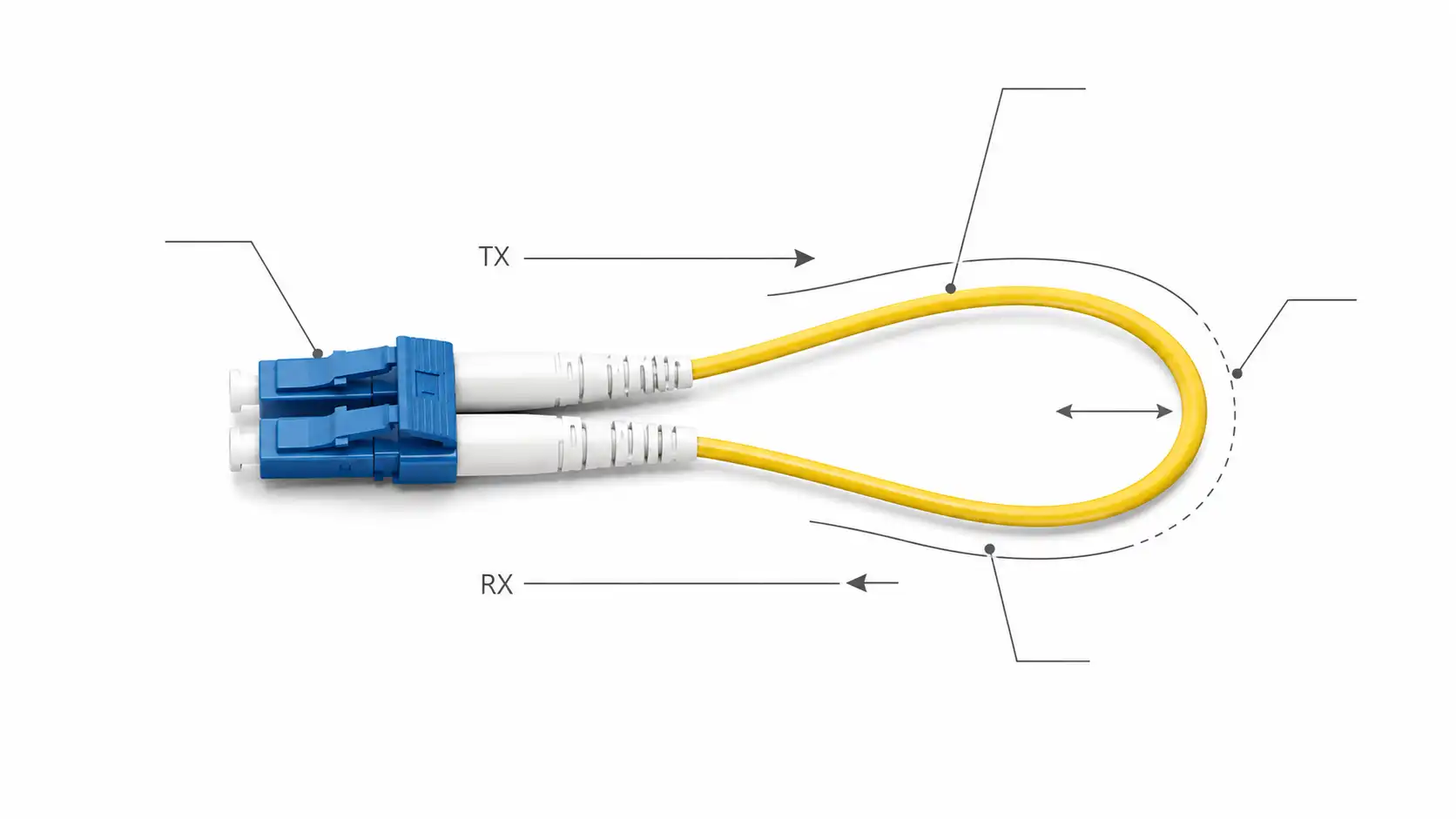
How a Fiber Loopback Works
Most optical interfaces have a separate transmit channel and receive channel. Normally TX sends light to a distant device and RX accepts light coming back from it. A loopback short-circuits that path inside the connector or module:
- The port emits an optical signal from its TX fiber(s).
- The loopback routes that light internally, passively, with no signal regeneration.
- The signal returns to the RX fiber(s) of the same port.
- The equipment or test set checks the returned signal: link state, received optical power, and any error or bit-error counters.
Because the device is receiving its own transmission, a loopback exercises the real TX and RX path rather than taking a static measurement. That makes it strong for isolation: a port that passes a clean loopback has a working local transmitter, receiver and interface under that test, which immediately narrows a fault to the cabling, patch panel or far-end device.
Fiber Loopback Types and Connector Options
Most loopbacks are a short simplex fiber routed inside a compact, rugged housing, terminated so that TX feeds back to RX. They are classified by connector type, fiber mode, polish, and - for multi-fiber versions - fiber count. The table below summarizes the common families.
| Loopback type | Connector(s) | Typical use | Notes |
|---|---|---|---|
| LC / SC loopback | LC, SC | Duplex transceiver and port testing (1G, 10G, 25G) | Compact, low loss, singlemode or multimode |
| MPO / MTP loopback | 8, 12 or 24 fibers | Parallel optics: 40G / 100G and beyond | Polarity, fiber count and pinning all matter |
| FC / ST / E2000 loopback | FC, ST, E2000 | Legacy plant, lab and instrument testing | Match exact connector and polish |
| Custom / attenuated loopback | Various | OEM test rigs, long-reach optics | Built-in attenuation for receiver protection |

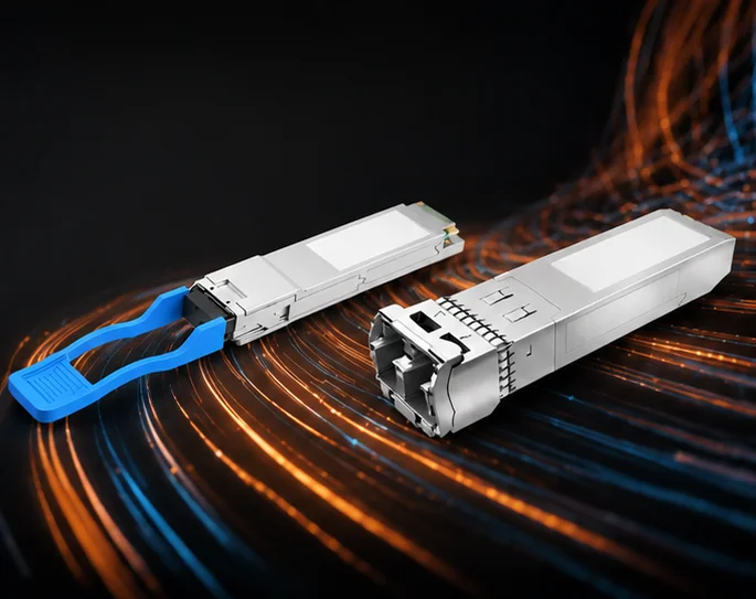
LC and SC Loopbacks
LC is the most common loopback because LC duplex ports dominate SFP, SFP+ and many other optics. An LC loopback drops into a single-lane duplex module and is available in singlemode and multimode, with UPC or APC polish on singlemode versions. SC loopbacks do the same job on SC interfaces still found in telecom, FTTx, media-converter and legacy gear. The two are not interchangeable; the practical difference between LC and SC connectors is size and latch design, and the connector on the loopback must match the port exactly.
MPO / MTP Loopbacks
MPO and MTP loopbacks are multi-fiber modules for parallel-optics interfaces. Instead of one TX-to-RX pair, they route several transmit lanes back to their matching receive lanes inside one connector, which is why fiber count, polarity and pinning have to be right. A purpose-built MPO/MTP fiber loopback module handles that internal mapping; a generic plug with the wrong scheme will fail a perfectly healthy transceiver. The configurations are covered in detail in the next section.
FC, ST and E2000 Loopbacks
These appear in older infrastructure, laboratory systems and test instruments. With legacy equipment, match the connector, polish and fiber type precisely - a mechanically similar connector is not enough if the interface or polish differs.
MPO / MTP Loopback Configurations: 8, 12 and 24 Fiber
An MPO loopback works by mirroring fiber positions: light leaving one transmit position must land on the receive position the transceiver expects. The mapping follows the same reversal logic used by Type B MPO cabling defined in TIA-568.3-D, and the connector interface itself is standardized as Type MPO in IEC 61754-7.

12-Fiber MPO Loopback
In a 12-fiber loopback, every position is paired across the centre line: 1 to 12, 2 to 11, 3 to 10, 4 to 9, 5 to 8, and 6 to 7. This full mirror returns each transmit fiber to its corresponding receive fiber.
8-Fiber MPO Loopback
Eight-fiber parallel optics such as 40GBASE-SR4 and 100GBASE-SR4 use four transmit lanes and four receive lanes - eight active fibers in total, as specified in the IEEE 802.3 parallel-optics standards. An 8-fiber loopback mirrors those four active transmit positions to the four active receive positions. When the optic uses a 12-position ferrule, the four unused fibers sit in the centre of the array and stay dark; the loopback simply leaves them open. Get the active-lane mapping wrong and the link reports down even though the module is fine.
24-Fiber MPO Loopback
A 24-fiber loopback applies the same straight/reversed polarity principle across two rows of twelve, returning each transmit position to its matching receive position. These are used for the highest-density parallel applications.
Gender and Pinning
An MPO loopback has to be the opposite gender to the port it plugs into: the guide pins on one ferrule must seat into the holes on the other, so the two cannot both be pinned or both unpinned. Equipment and transceiver MPO ports are typically pinned (male), so loopbacks are usually supplied unpinned (female) - but confirm your port before ordering. If polarity terms like Type A, B and C are unfamiliar, settle them first; this overview of MPO polarity methods (A, B and C) explains how positions map across a connector.
Field note: when a 40G or 100G SR4 port reports "down" with a brand-new MPO loopback, the cause is far more often a polarity or gender mismatch than a dead port. Verify the loopback gender and lane mapping before you condemn the transceiver.
Singlemode vs Multimode Loopback (and Polish)
Fiber mode is the decision you cannot get wrong. A singlemode loopback belongs on singlemode optics and OS2 fiber; a multimode loopback belongs on OM3 or OM4 multimode optics. A 10GBASE-SR module needs a multimode LC loopback, while a 10GBASE-LR module needs a singlemode one, even though both accept the same LC connector. The connector fitting tells you nothing about whether the mode is right - the practical distinctions between singlemode and multimode fiber govern wavelength and reach, and a mismatch produces excess loss, unstable readings or a false fail.
Polish matters too. On singlemode connectors, UPC (blue) and APC (green) are not compatible - never mate UPC to APC, as the end-face geometry mismatch degrades performance and can damage the ferrule. Match connector, fiber mode and polish before any test.

Advantages and Limitations of Fiber Loopback Testing
Loopbacks earn their place in the toolkit because they are fast, passive, inexpensive and require no remote endpoint. They let you exercise the actual transmit-and-receive path of a port, which is closer to a functional check than a static loss reading, and they make bench QC, burn-in and field fault-isolation quick.
Their limits are just as important. A loopback is sometimes described as "end-to-end" testing, but strictly it verifies the local interface - the transceiver and port talking to themselves - not the full link between two sites. It cannot locate a break in a cable run, and it cannot prove sustained data integrity under load. High-power long-reach optics add another caveat: a near-zero-length loopback can drive the receiver past its maximum input and cause errors, which is why long-reach modules are tested with an attenuated loopback. For anything beyond a local check, a loopback works alongside other methods rather than replacing them.
Common Faults and How to Avoid Them
Dirty End Face
Contamination is the most frequent cause of failed optical tests. A dust cap pulled too early or exposure to a dirty environment leaves debris that scatters light, raises loss, and can transfer onto the mating port. Inspect with a scope, clean with proper fiber tools or lint-free wipes and isopropyl alcohol, then re-inspect - never use paper towels, cotton wool or ordinary swabs. The pass/fail end-face criteria are defined in IEC 61300-3-35, and this guide to inspecting and cleaning connector end faces covers the workflow.
Mechanical Damage
Forcing a connector, or repeatedly inserting and removing it when you cannot see the end face, damages ferrules and can fail in service even if it works at first. Align the connector key and seat the loopback axially without force. On MPO modules, hold the connector body - not the boot or fiber - when inserting and removing.
Macrobend Loss
Tight bends attenuate the signal. Respect the cable's minimum bend radius - for many patch and loopback leads this is roughly 10 to 20 times the outer diameter - and never yank or push the cable, which can scratch or break the fiber.
Insertion Loss and Return Loss Drift
Higher-than-expected insertion loss points to a faulty connector or cable; poor return loss usually means a contaminated or mismatched end face. Use quality loopbacks with low insertion loss and adequate return loss, and verify them periodically so the loopback is not the thing introducing error into your results.
Fiber Loopback vs OTDR vs BERT
A loopback is one tool among several, each with a clear boundary. Confusing them is how good test data gets misread.
| Tool | What it does | When to use it |
|---|---|---|
| Fiber loopback | Returns TX to RX to test the local interface | Transceiver, port and equipment diagnostics |
| OTDR | Locates faults and measures events along the fiber | Cable-route troubleshooting and link characterization |
| BERT | Measures bit errors over time under load | Data-integrity and performance validation |
Put plainly: a loopback confirms the local port, an OTDR characterizes the fiber path and pinpoints breaks, and a BERT verifies that the link carries data cleanly. A port that passes loopback but fails once patched is your cue to reach for the OTDR, not to keep swapping transceivers.
How to Choose the Right Fiber Loopback
Before ordering or testing, match the loopback to the interface on every axis that affects the result:
- Connector type - LC, SC, FC, ST or MPO/MTP, matching the port exactly.
- Fiber mode - singlemode for SM optics, multimode (OM3/OM4) for MM optics.
- Polish - UPC or APC on singlemode; never mix the two.
- MPO fiber count and mapping - 8, 12 or 24 to suit the optic, with the active lanes correctly mirrored.
- MPO gender - opposite to the port; confirm pinned vs unpinned before buying.
- Attenuation - plain for short-reach optics, a rated value for long-reach modules to avoid receiver overload.
- Optical quality - low insertion loss and good return loss so the loopback itself is not the variable.
FAQ About Fiber Optic Loopbacks
Q: What is the purpose of a fiber optic loopback?
A: It returns an optical signal from a port's transmit side to its receive side so a transceiver, port or interface can be tested locally, with no remote device. It is used mainly for transceiver checks, port diagnostics, commissioning and fault isolation.
Q: What types of fiber loopback are available?
A: LC, SC, FC, ST, E2000 and MPO/MTP, in both singlemode and multimode, and with UPC or APC polish on singlemode versions. LC, SC and MPO/MTP are the ones used most for transceiver testing.
Q: How is an MPO loopback used?
A: It tests parallel-optics interfaces such as 40GBASE-SR4 and 100GBASE-SR4 by mirroring the active transmit lanes back to the matching receive lanes. The fiber count, polarity, mapping and gender must all match the optic, which makes MPO loopbacks more configuration-sensitive than LC or SC.
Q: Can I use a singlemode loopback on a multimode transceiver?
A: No. It will mate physically, but the optical behaviour is wrong and the result is meaningless. Match the fiber mode to the optic every time, and match the polish as well.
Q: Do I need an attenuated loopback?
A: It depends on the optic's reach, not its speed. Short-reach optics (SR, SR4) generally pass with a plain loopback. Long-reach optics (ER, ZR, LR4) usually need an attenuated loopback, because a short loopback can drive their receiver past its maximum input. Size the attenuation so received power lands inside the receiver's operating window.
Q: Why does my loopback test fail?
A: In rough order of likelihood: a dirty end face, the wrong loopback type or fiber mode, an MPO polarity, mapping or gender error, a UPC/APC mismatch, missing attenuation on a long-reach optic, a port left administratively down or in the wrong mode, and only then a faulty transceiver or port.
Q: How do I clean a fiber loopback connector?
A: Inspect first, then clean with proper fiber-cleaning tools or lint-free wipes and isopropyl alcohol, and re-inspect before mating. Do not use paper towels, cotton wool or ordinary cotton swabs, which leave fibres and residue.
Q: Is fiber loopback better than OTDR or BERT?
A: Not better - different. A loopback checks the local interface, an OTDR locates faults along the cable, and a BERT validates data quality under load. They complement each other in a full test workflow.
Q: Can a loopback find a break in a cable?
A: No. It tests the local interface, not the fibre run. To locate a break or measure events along a link, use an OTDR.
Conclusion
A fiber optic loopback is a small, passive tool that proves a local optical interface fast and without a remote endpoint, which makes it ideal for transceiver QC, port diagnostics and quick fault isolation. To get a result you can trust, match the connector, fiber mode and polish, and for MPO/MTP also match the fiber count, polarity, lane mapping and gender. Keep end faces clean, use a rated attenuated loopback on long-reach optics, and remember the boundary: the loopback confirms the port, an OTDR characterizes the cable, and a BERT validates the data.