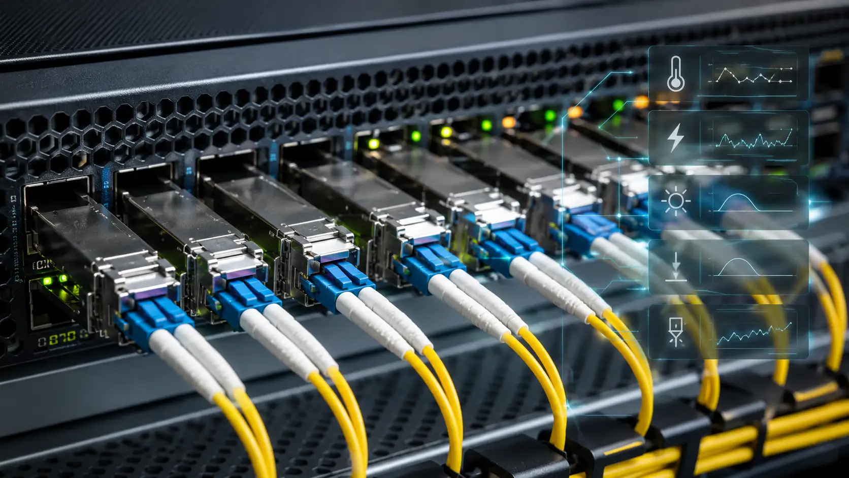
SFP DOM (Digital Optical Monitoring) is a diagnostic feature that lets a switch or router read real-time operating data from an optical transceiver. Instead of only telling you whether a fiber link is up or down, DOM reports how healthy the link actually is: module temperature, supply voltage, transmit (Tx) optical power, receive (Rx) optical power, and laser bias current. Those five values are where most physical-layer problems show up first.
This matters because many fiber faults never start as a clean link failure. A port can stay "up" while Rx power sits a fraction of a decibel above the low-warning threshold, while the module slowly overheats, or while the laser ages and draws more bias current every week. Reading DOM data is how you catch a weak optical link before it turns into an outage, and how you decide whether the problem is local, remote, or in the fiber path.

What Is SFP DOM (Digital Optical Monitoring)?
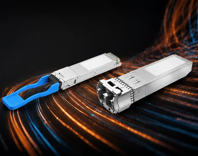
SFP DOM is a monitoring function built into many SFP and SFP+ transceivers, as well as SFP28, QSFP+, and QSFP28 modules. It lets the host device - a switch, router, firewall, or media converter - read diagnostic values directly from the module without ever unplugging the fiber. In effect, the optical module becomes a small sensor reporting on its own health and on the light arriving from the far end.
A DOM-capable module typically exposes:
- Module temperature - how hot the transceiver is running internally.
- Supply voltage - the electrical rail the host is feeding the module.
- Tx bias current - the current driving the laser.
- Tx optical power - the light the module is launching into the fiber.
- Rx optical power - the light the module is receiving from the remote transmitter.
- Warning and alarm thresholds - the high/low limits the switch compares each reading against.
DOM does not replace proper fiber test gear such as an optical power meter or OTDR. What it gives you is fast, no-touch visibility into the physical layer, which is usually enough to localize a problem before you reach for a meter.
DOM vs DDM: Is There a Difference?
In day-to-day networking, DOM and DDM describe the same capability. DOM stands for Digital Optical Monitoring; DDM stands for Digital Diagnostic Monitoring. Some vendors print "DOM supported" on a datasheet, others print "DDM supported," and a few write "DDM/DOM" - but for selection and troubleshooting they point to the same thing: the module's ability to report live diagnostic data to the host.
You may also see a third label, RGD (rugged/industrial temperature grade), listed alongside DOM on certain product pages. If you want a fuller breakdown of how these terms relate, this guide on the DDM, DOM, and RGD functions of SFP modules covers the distinctions. For the rest of this article, "DOM" and "DDM" are used interchangeably.
What Parameters Does SFP DOM Monitor?
DOM data is only useful once you know what each value means and what counts as normal. The catch is that "normal" is not universal: thresholds depend on the module type, wavelength, reach, vendor design, and host platform. Always compare a reading against the module datasheet or the threshold table the switch itself reports.

| DOM parameter | What it means | Why it matters |
|---|---|---|
| Temperature | Internal module temperature | Sustained heat shortens module life and can cause instability or link flaps. |
| Supply voltage | Voltage the host supplies to the module | Out-of-range voltage points to host power or line-card problems, not the optics. |
| Tx bias current | Current used to drive the laser | A slowly rising trend can signal laser aging or thermal stress. |
| Tx optical power | Optical power launched into the fiber | Low Tx power suggests a weakening or failing local transmitter. |
| Rx optical power | Optical power received from the remote side | Low Rx power usually means link loss: dirty connectors, distance, bad fiber, or a weak remote Tx. |
A quick note on dBm and mW
Optical power in DOM is reported in dBm, a logarithmic scale referenced to one milliwatt: 0 dBm equals 1 mW, -10 dBm is 0.1 mW, and -20 dBm is 0.01 mW. Because the scale is logarithmic, roughly every 3 dB halves or doubles the power. A receive reading that slips from -10 dBm to -13 dBm means the module is now seeing about half as much light, even though the number "only" changed by three. This is why there is no single good dBm figure to memorize - the acceptable Rx and Tx window is defined per module in its datasheet.
Temperature
Temperature tells you how hot the transceiver is running inside its cage. A module packed into a dense switch, a hot aisle, or a poorly ventilated cabinet will run warmer than the same part in open air. High temperature does not automatically mean a defective module - blocked airflow, high ambient temperature, neighboring high-power optics, or an overloaded chassis cooling design are all common causes. It is still worth treating as a real warning, because optical components are sensitive to thermal stress over time.
Supply Voltage
The supply voltage reading shows whether the host is feeding the module within its expected electrical range. Voltage problems are less common than low optical power, but they are diagnostically useful precisely because of where they point. If several modules in the same switch or on the same line card report abnormal voltage at once, suspect the host platform or that slot before you start swapping optics - the odds of multiple modules failing identically are low.
Tx Bias Current
Tx bias current is one of the more useful DOM values for long-term health tracking, because it tends to drift rather than jump. A healthy module sits comfortably inside its bias range; as the laser ages or runs hot, it needs more current to hold the same optical output. A bias current that climbs slowly over weeks while temperature and Tx power stay flat is far more telling than any single high reading. That trend is your early-warning signal - a one-off value near the limit is not.
Tx Optical Power
Tx optical power shows how much light the module is launching into the fiber. If it falls below the specified range, the local transmitter is likely weakening. The important discipline here is not to judge the whole link from Tx alone: a module can transmit perfectly while the far end receives poor power because of dirty connectors, excess cable loss, bad splices, the wrong fiber type, or a damaged patch cord somewhere in between.
Rx Optical Power
Rx optical power shows how much light the module receives from the remote transmitter, and it is usually the first value engineers check when a link is unstable. Low Rx power commonly comes from contaminated connector end faces, excessive link distance, too many patch panels or splices, fiber bends or damage, the wrong transceiver reach, a wavelength or fiber-type mismatch, or simply a weak Tx at the remote module.
High Rx power is a problem too, and it is easy to overlook. On a short link, using a long-reach transceiver without padding the signal can overload the receiver. In that case, an inline fiber optic attenuator sized to the link brings Rx back into the module's working range. Both extremes - too little and too much light - push the receiver out of its comfort zone.
Why SFP DOM Matters for Fiber Link Troubleshooting
A link status of "up" does not mean the optical path is healthy. The interface stays up as long as the receiver can recover enough signal, but it can be running on almost no margin. DOM answers the questions that a bare up/down state cannot: Is Rx power creeping toward the warning threshold? Is the module overheating? Is the laser aging? Is the remote side actually sending enough power? Is the fault more likely local, remote, or in the fiber?
This is where DOM earns its place on intermittent problems. A link might only flap when the room warms up, when someone moves a patch cord, or when vibration disturbs a marginal splice. Without DOM the interface just looks "flaky." With DOM you can see whether optical power is drifting toward the edge and act before users notice.
How to Read SFP DOM Values on a Switch
The exact command depends on the vendor and the software version, but the families are familiar. On most enterprise switches you will use something close to one of these:

- Cisco IOS / NX-OS: show interfaces transceiver and show interfaces transceiver detail, or show interface ethernet x/y transceiver details.
- Juniper / Arista: show interfaces diagnostics optics, show chassis hardware, and similar platform variants.
- Linux hosts and many white-box switches: the ethtool utility, using ethtool -m ethX (also written --module-info), which decodes the module EEPROM and, if the driver and module support it, the optical diagnostics.
A typical DOM output lists the current temperature, voltage, bias, Tx power, and Rx power alongside the four threshold levels: high alarm, high warning, low warning, and low alarm. The example below is illustrative - the values are made up to show the shape of the output, not a real module:
Example output (illustrative values only)
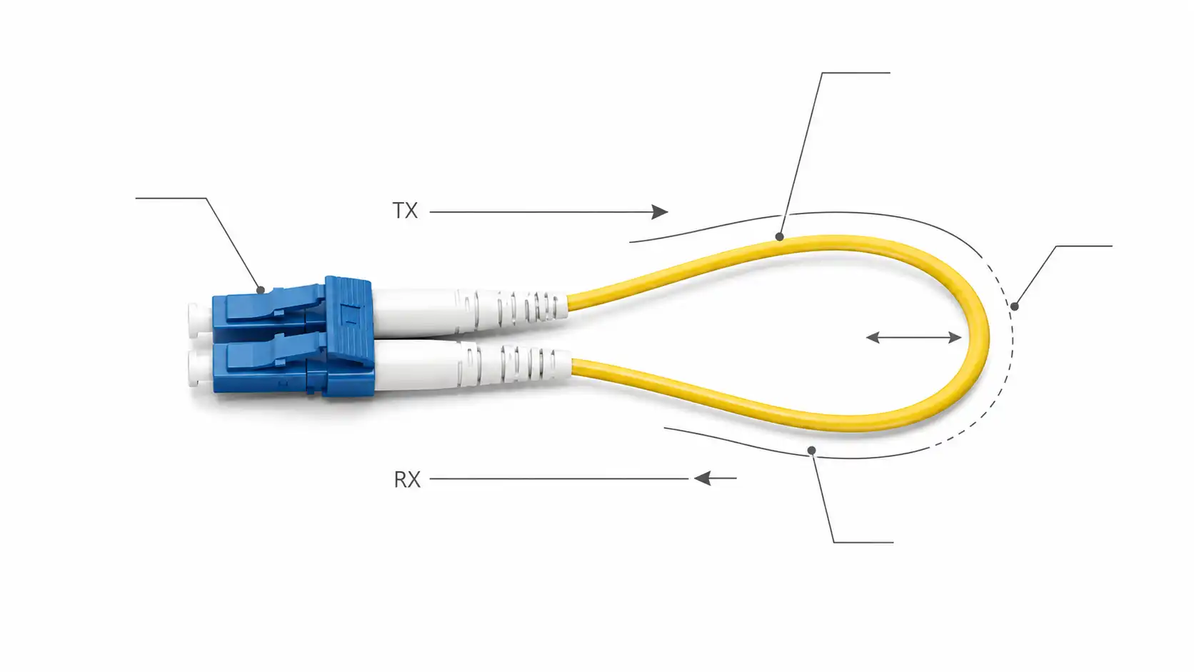
Identifier : 0x03 (SFP)
Connector : 0x07 (LC)
Transceiver type : 10G Ethernet: 10GBASE-LR
Laser wavelength : 1310 nm
Optical diagnostics : Yes (SFF-8472)
Current Low Alarm Low Warn High Warn High Alarm
Module temperature 48.2 C -5.0 C 0.0 C 70.0 C 75.0 C
Supply voltage 3.31 V 3.10 V 3.13 V 3.46 V 3.50 V
Tx bias current 38.4 mA 2.0 mA 4.0 mA 70.0 mA 80.0 mA
Tx optical power -2.6 dBm -8.2 dBm -7.0 dBm 2.0 dBm 3.0 dBm
Rx optical power -16.8 dBm -18.0 dBm -17.0 dBm -1.0 dBm 0.5 dBm
The habit that separates a useful reading from a misleading one is to never judge a module by a single number. Check three things together: the current value, the warning and alarm thresholds it is being measured against, and the trend over time. In the example above, Rx power is technically in range, but it sits only about 0.2 dB above the low-warning threshold - a value worth watching closely, especially if it has been sliding over several weeks.
| Reading | Example value | Relevant threshold | What it suggests | Suggested action |
|---|---|---|---|---|
| Rx optical power | -16.8 dBm | Low warning -17.0 dBm | Almost no margin left | Inspect and clean the fiber path; compare with the remote Tx |
| Tx bias current | 38.4 mA | High warning 70 mA | Well within range; watch the trend | Record a baseline; act only if it keeps rising |
| Module temperature | 48.2 °C | High warning 70 °C | Normal for a populated chassis | No action; keep airflow clear |
| Supply voltage | 3.31 V | 3.13–3.46 V window | Healthy host power | No action |
SFP vs SFP+ vs SFP28 vs QSFP28: what changes in the display
The DOM fields are broadly the same across SFP, SFP+, and SFP28, because all three are single-channel modules with one Tx/Rx pair, so you read one set of values. QSFP+ and QSFP28 are different. They carry four lanes, so a switch usually reports Tx bias, Tx power, and Rx power per lane - four sets of figures - plus a single shared temperature and voltage. When you read DOM on a 40G or 100G QSFP module, expect per-lane data and check each lane individually; one weak lane can drag a parallel link even when the others look fine.
How to Interpret Common SFP DOM Warnings
Low Rx power
Low Rx power means the local module is not receiving enough light from the far end - the single most common DOM warning. Likely causes include dirty connectors, excessive link loss, a weak remote transmitter, bad patch cords, the wrong fiber type, the wrong transceiver reach, or a damaged route. The judgment call that saves the most time: if local Rx power is low but the remote module's Tx power reads normal, the fiber path between them is the first place to inspect, not the optics. Clean and inspect both connector end faces, verify fiber type and wavelength, confirm distance against the loss budget, swap suspect patch cords, and measure with an optical power meter if the path is still in doubt.
High Tx bias current
A high Tx bias reading means the laser is working harder than usual. Treat a single high value against the module's threshold table, but pay real attention to a rising trend. Compare the reading with the module spec, check whether the module is also running hot (heat and bias often move together), review historical data if your monitoring keeps it, and plan a replacement during a maintenance window if bias keeps climbing. A flat, slightly elevated bias is usually fine; a steady upward slope is the signal to act.
High temperature
High module temperature usually traces back to the environment rather than the part: poor airflow, a hot cabinet, dense cabling, or high-power modules crowded together. Check chassis airflow and fan status, clear any obstructions, review the cabinet temperature, and avoid stacking too many high-power optics in one area on platforms with thermal limits. Replace the module only if it stays hot in a normal, well-ventilated environment - at that point the optics, not the room, are the suspect.
DOM shows N/A or unsupported
If DOM reads N/A, unsupported, or unavailable, the transceiver is not necessarily bad. It may simply not support DOM, the host may not read DOM for that module, or the module's coding may not be recognized by the switch. Confirm whether the module supports DOM/DDM, check the switch compatibility list, try the module in another supported port, update device software if the vendor recommends it, and use a transceiver coded for the platform if needed.
Normal Rx power but CRC errors
Sometimes Rx power looks fine yet the interface still logs CRC errors, input errors, or drops. When the light level is adequate but the link is dirty, the cause is usually signal quality rather than simple attenuation: damaged or contaminated connectors, marginal patch cords, incompatible optics, electrical noise, a host-port issue, or borderline high-speed performance. DOM is one input here, not the whole answer - read it together with interface counters, error logs, and a physical inspection.
Low Rx Power Troubleshooting: A Step-by-Step Flow
When DOM flags low Rx power, working a fixed order keeps you from swapping good hardware. A practical sequence:
- Step 1 - Confirm the value and its thresholds. Read the current Rx power and the module's own low-warning and low-alarm limits from the switch or datasheet.
- Step 2 - Compare local Rx with the remote Tx. This single comparison localizes the fault: normal remote Tx with low local Rx points at the path, not the far-end laser.
- Step 3 - Clean and inspect both connector end faces. Contamination is the most common and most reversible cause; this step alone resolves a large share of low-Rx cases. A primer on fiber end-face contamination and how to prevent it is worth keeping on hand for field crews.
- Step 4 - Verify the optical design. Check fiber type, wavelength, reach, and the link's loss budget against what the link actually requires.
- Step 5 - Swap suspect patch cords and re-seat connectors. Move on from passive cabling only after it is ruled out.
- Step 6 - Measure with a power meter or OTDR. Quantify the path loss if the link is still suspect after cleaning and re-seating.
- Step 7 - Replace the module last. Swap optics only after the fiber path and the remote end have been cleared.
A short field example shows why the order matters. On one 10G single-mode link, local Rx power had drifted from roughly -10 dBm at install to about -16 dBm, sitting just above the low-warning threshold while the interface still showed "up." The remote Tx power read normal, which pointed away from the far-end laser. Cleaning and re-seating the LC connectors at a mid-span patch panel brought Rx back to around -10.5 dBm. No module replacement was needed - and if the connectors had been skipped in favor of a quick optic swap, the real fault would have come straight back.

SFP DOM and SFF-8472: What the Standard Means
DOM is not just a marketing label; it rests on a published specification. SFF-8472 defines the diagnostic monitoring memory map and the two-wire management interface that lets a host read operating data and threshold values from an SFP or SFP+ module. That standard is why so many switches can display similar DOM fields across different supported modules - the data layout is common. The specification is maintained by the SFF Technology Affiliate Technical Work Group and published through SNIA's SFF specifications library, which absorbed the original SFF Committee in 2016.
Standard support does not guarantee that every module and every switch behave identically. Compatibility coding, firmware, vendor implementation choices, and platform support still decide whether a given module's DOM data displays cleanly on a given host. SFF-8472 sets the common language; the host and module still have to agree to speak it.
Best Practices for Using SFP DOM in Daily Operations
DOM is most valuable as part of a repeatable process rather than a panic-time spot check. Start by recording a baseline while the link is healthy - note the normal Tx power, Rx power, temperature, and bias current - so future changes are obvious instead of guesswork. From there, watch trends rather than reacting only to alarms: a slow Rx decline or a steady bias rise often tells you more than a single warning event ever will.
Read DOM alongside interface counters. CRC errors, drops, link flaps, and DOM readings together tell a far more complete story than any one of them alone. And keep DOM in its lane - for serious fiber faults, back it with real inspection and measurement using an optical power meter and fiber inspection tools, plus proper connector cleaning. DOM points you to the problem; test gear confirms it.
Integrating DOM with SNMP and NMS monitoring
You do not have to read DOM by hand. Most enterprise switches expose DOM values over SNMP - commonly through the ENTITY-SENSOR MIB or a vendor MIB - so an NMS or telemetry collector can poll temperature, voltage, bias, and Rx/Tx power on a schedule and alert when a reading crosses a threshold. On newer platforms, streaming telemetry does the same at higher frequency. Wiring DOM into your NMS turns it from a manual check into continuous monitoring with a recorded baseline, which is what makes "catch it before the outage" realistic at scale.
FAQ
Q: Is SFP DOM the same as DDM?
A: In practical networking, yes. Both describe digital diagnostic monitoring - the module reporting live temperature, voltage, bias, and Tx/Rx power to the host. Vendors differ on which term they print.
Q: How do I enable DOM on a switch?
A: On most platforms DOM is read with a show or diagnostic command rather than "enabled" - for example the Cisco show interfaces transceiver detail family, Juniper's optics diagnostics commands, or ethtool -m on Linux. A few platforms require enabling transceiver monitoring in configuration first, so check your switch's documentation. The module itself must support DOM/DDM for any of these to return data.
Q: Do all SFP modules support DOM?
A: No. Many modern optical modules support DOM/DDM, but not every one does. Some older modules, low-cost parts, copper SFPs (1000BASE-T), and passive direct-attach cables provide limited diagnostics or none at all, since they have no laser to monitor.
Q: What is Tx bias current in an SFP, and why does it matter?
A: Tx bias current is the electrical current driving the module's laser. It matters mainly as a trend: a bias current that rises steadily over time while temperature and Tx power stay stable can indicate the laser is aging, making it a useful early-warning signal for planned replacement.
Q: What is a good Rx power level for an SFP?
A: There is no universal number. The acceptable receive-power window depends on the transceiver type and vendor spec. Always compare the reading against the module datasheet or the threshold table the switch reports, not a generic figure.
Q: What causes low Rx power on an SFP module?
A: Common causes are contaminated connector end faces, excessive link distance, too many patch panels or splices, fiber bends or damage, the wrong transceiver reach, a fiber-type or wavelength mismatch, or a weak Tx at the remote module. Compare local Rx with the remote Tx to narrow it down before replacing anything.
Q: Why does my switch show DOM as N/A?
A: DOM can read N/A if the module does not support diagnostics, if the switch does not read DOM for that module, if the module coding is not recognized, or if the platform software cannot decode the data. It does not, on its own, mean the module is faulty.
Q: What does an SFP DOM alarm mean?
A: An alarm means a reading has crossed the module's high-alarm or low-alarm limit - a more serious threshold than a warning. It calls for prompt investigation: identify which parameter alarmed (Rx power, temperature, bias, and so on) and work that specific cause rather than treating every alarm the same way.
Q: Can DOM data be monitored by SNMP or an NMS?
A: Yes. Most enterprise switches expose DOM values over SNMP (often via the ENTITY-SENSOR MIB or a vendor MIB), and newer platforms can stream them through telemetry. That lets an NMS poll and alert on temperature, voltage, bias, and Rx/Tx power automatically.
Q: Can DOM predict a module failure?
A: DOM can flag early warning signs - particularly through temperature, Rx power trends, and Tx bias current trends - but it cannot predict every failure. It gives engineers far better visibility than link status alone, which is usually enough to act before an outage.
Q: Should I replace a module when Rx power is low?
A: Not immediately. Low Rx power is often caused by the remote transmitter, dirty connectors, fiber loss, distance, or patch-cable issues. Clean and inspect the fiber path first, compare local and remote DOM readings, and replace hardware only after the path and far end are cleared.
Key Takeaways
SFP DOM gives network teams a practical window into the health of optical transceivers and fiber links. By reading temperature, supply voltage, Tx bias current, Tx power, and Rx power - and by reading them as a set, against thresholds, over time - you can find most physical-layer problems before they become complete outages. For troubleshooting, DOM explains why a link can be "up" yet unstable. For operations, it turns guesswork into trend monitoring. For purchasing, DOM/DDM support and correct platform coding should be standard requirements on any link that matters.
The simplest next step is to check whether your current optical modules support DOM, record the normal values for your healthy links, and choose compatible, properly coded DOM-capable transceivers when you upgrade or expand. The visibility costs nothing once the modules support it, and it pays for itself the first time it saves a truck roll.