A fiber optic circulator is a passive, non-reciprocal device that directs light from one port to the next port in a defined sequence. In a common three-port design, light entering Port 1 exits Port 2. Light returning to Port 2 is then routed to Port 3 instead of traveling back to Port 1.
This directional behavior is useful whenever an optical system must separate outgoing and returning light. Common examples include single-fiber bidirectional links, reflective Fiber Bragg Grating systems, OTDR and reflectometry, double-pass optical amplifiers, fiber sensing, and optical coherence tomography.
This guide explains the operating principle, port map, main types, applications, selection criteria, and acceptance tests. A circulator is one of several passive optical devices, and it must be selected as part of the complete source, fiber, detector, connector, and measurement architecture.

Quick Answer: What Does a Fiber Optic Circulator Do?
A three-port optical circulator normally provides two essential low-loss paths:
- Port 1 to Port 2: sends source light toward a link or reflective component.
- Port 2 to Port 3: sends returning light toward a receiver or measurement instrument.
Light entering Port 2 does not retrace the Port 1-to-Port 2 path. It is redirected to Port 3. That is why a circulator can separate counter-propagating signals without simply discarding the returning light.
| Optical path | Typical interpretation | Relevant specification |
|---|---|---|
| 1 → 2 | First intended transmission path | Insertion loss |
| 2 → 3 | Second intended transmission path | Insertion loss |
| 3 → 1 | Available only in a fully circulated design | Insertion loss, if specified |
| 2 → 1 | Unwanted reverse leakage | Isolation |
| 1 → 3 | Unwanted skip-port leakage | Directivity or crosstalk |
What Is a Fiber Optic Circulator?
IEC 62077:2022 describes fiber optic circulators as passive, non-reciprocal devices with three or more ports that transmit optical power directionally. The ports may be optical fibers or fiber optic connectors.
"Non-reciprocal" is the key term. In a reciprocal component, reversing the propagation direction normally allows light to retrace the same optical path. A circulator behaves differently: the reverse-traveling signal is sent to a different port.
The component does not amplify the signal, generate a wavelength, correct transceiver polarity, or replace a WDM device. It provides controlled routing between optical ports. The RP Photonics Encyclopedia article on Faraday Circulators by Dr. Rüdiger Paschotta describes the same sequential routing principle and its relationship to Faraday isolators.
How Does a Three-Port Optical Circulator Route Light?
The port arrows in the product drawing are more important than the physical numbering alone. A typical arrangement places the source at Port 1, the shared fiber or reflective element at Port 2, and the detector at Port 3.
Full Circulator vs Quasi-Circulator
A fully circulated three-port device can provide 1→2, 2→3, and 3→1 paths. A quasi-circulator, sometimes described in standards as an incompletely circulated device, may provide only the paths required by the intended application.
IEC 61753-091-02:2022, for example, addresses non-connectorized, single-mode, three-port incompletely circulated circulators for controlled environments. This is why the presence of three physical ports does not prove that all three sequential paths are usable or have the same limits.
Before ordering, record every required input-to-output path. If the system only needs 1→2 and 2→3, a quasi-circulator may be sufficient. If Port 3 must also route light to Port 1, the data sheet must explicitly specify that path.
Fiber Optic Circulator Working Principle
Most conventional fiber optic circulators use magneto-optic non-reciprocity based on the Faraday effect. A Faraday rotator changes the polarization direction of light in a magnetic field. Unlike an ordinary reciprocal waveplate, the rotation does not cancel when the light travels through the device in the opposite direction.
Practical designs combine the Faraday rotator with waveplates, polarizers, birefringent beam displacers, collimating optics, and precision alignment structures. The optical arrangement makes forward- and backward-traveling light reach different output fibers.

Simplified Forward Path
- Light entering Port 1 is collimated.
- The design separates or manages the polarization components.
- Waveplates and the Faraday rotator establish the required polarization state.
- The beams are recombined and focused into Port 2.
Simplified Return Path
- Returning light enters Port 2 and travels through the optical assembly in the reverse direction.
- The non-reciprocal rotation does not undo the original polarization change.
- The resulting polarization and spatial path differ from the Port 1-to-Port 2 route.
- The light is focused into Port 3 instead of Port 1.
The exact internal construction varies. System designers normally do not need to reproduce the internal optics, but they do need to understand that wavelength, polarization, alignment, temperature, optical power, and connector reflections can change the measured performance.
Main Types of Fiber Optic Circulators
Three-Port and Multiport Circulators
A three-port unit is the usual choice for separating outgoing and returning light. Four-port and higher-port versions support additional sequential paths but may increase package complexity and total system loss. More ports are useful only when the architecture requires them.
Polarization-Independent Circulators
A polarization-independent design accepts changing input states of polarization, which is useful in ordinary single-mode links where bending, stress, temperature, and movement can alter the state of polarization. The data sheet should still define polarization-dependent loss and any polarization-mode-dispersion limit that matters to the application.
Polarization-Maintaining Circulators
A polarization-maintaining optical circulator is intended to preserve a defined polarization axis in sensing, interferometric, coherent, and laser systems. It must be used with correctly aligned polarization-maintaining fiber.
Connector keying, splice rotation, slow-axis or fast-axis requirements, launch polarization, and polarization extinction ratio all matter. A PM component cannot correct an incorrectly aligned source or splice.
Manufacturer documentation such as the Thorlabs polarization-maintaining circulator range also shows why wavelength, connector, axis alignment, and path-specific specifications must be checked by part number.
Wavelength-Specific, Broadband, and High-Power Versions
Circulators may be optimized for telecom bands, sensing wavelengths, laser wavelengths, or broadband imaging sources. A nominal 1310 nm or 1550 nm label does not prove acceptable performance across a wider band.
Broadband OCT circulators are a product-specific category. A narrowband telecom device should not be used with a broadband source unless the guaranteed wavelength-dependent loss, polarization behavior, return loss, and dispersion are suitable. High-power versions also require explicit continuous-power and peak-power ratings rather than a generic "high power" description.

Key Fiber Optic Circulator Specifications
| Specification | What it describes | Why it matters |
|---|---|---|
| Operating wavelength and bandwidth | The qualified spectral range | Loss, isolation, PDL, and reflections can change with wavelength |
| Insertion loss | Power lost through an intended path such as 1→2 | Consumes the link or measurement budget |
| Isolation | Suppression of reverse leakage such as 2→1 | Protects the source and separates counter-propagating signals |
| Directivity | Suppression of skip-port leakage such as 1→3 | Limits source leakage into the detector path |
| Return loss | Ratio between incident power and reflected power at the device interface | Important for reflection-sensitive lasers and measurements |
| PDL | Change in attenuation as input polarization changes | Important in polarization-independent systems |
| PER | Ability of a PM component to preserve the intended polarization | Important in PM sensing, lasers, and interferometers |
| PMD | Differential delay associated with polarization modes | Can matter in high-speed or precision systems |
| Optical power handling | Maximum permitted continuous and, where applicable, peak power | Prevents optical or thermal damage |
| Fiber and connector | SMF, PMF, specialty fiber, connector type, and polish | Must match the source, detector, and installed interfaces |
| Environmental range | Operating and storage temperature plus other qualified conditions | Determines suitability for the deployment environment |
These measurements are not interchangeable. IEC 61300-3-4:2023 describes methods for measuring attenuation of optical components, while IEC 61300-3-6:2008 addresses return-loss measurement. IEC 61300-3-2:2009 covers polarization-dependent loss, and IEC 61300-3-55:2020 covers PER and keying accuracy for PM passive components.
FOCC's single-channel insertion-loss tester and polarization extinction ratio tester illustrate the different measurement functions required for ordinary loss and PM performance.
How to Read an Optical Circulator Data Sheet
A product name such as "1550 nm three-port circulator" is not a complete specification. Read the data sheet in the following order.
| Data-sheet field | Question to answer | Common mistake |
|---|---|---|
| Port diagram | Which input-to-output paths are guaranteed? | Assuming every three-port device supports 3→1 |
| Typical vs guaranteed values | Which limits are maximum or minimum under stated conditions? | Building a design from a typical value |
| Test wavelength or band | Are specifications valid across the full source spectrum? | Using a center-wavelength value for a broadband source |
| Path-specific performance | Are 1→2 and 2→3 losses identical or separately specified? | Applying one path value to every direction |
| Polarization conditions | Is the device PI, polarizing, or PM, and how are PDL or PER defined? | Using a PI unit where axis preservation is required |
| Connector and fiber | What fiber type, connector, polish, key, and pigtail are supplied? | Mating APC and UPC or mismatching PM axes |
| Power and environment | What continuous, peak, temperature, and package limits apply? | Assuming all units with the same wavelength have equal ratings |
| Test conditions | What launch, reference, detector, and environmental conditions produced the value? | Comparing specifications measured under different conditions |
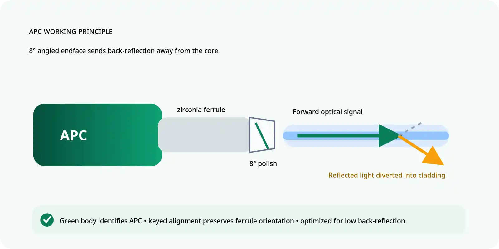
Where reflections matter, match the connector polish required by the architecture. FOCC's guide to APC vs UPC connector polish explains why angled and non-angled interfaces should not be directly mated.
Optical Circulator vs Isolator, Coupler, Switch, and WDM
| Device | Primary function | Reverse-traveling light | Typical use |
|---|---|---|---|
| Optical circulator | Routes light sequentially between ports | Redirected to another port | BiDi links, reflective devices, OTDR, sensing |
| Optical isolator | Allows forward transmission and suppresses reverse transmission | Blocked, absorbed, or strongly attenuated | Laser and amplifier protection |
| Optical coupler | Splits or combines optical power | Follows reciprocal split paths | Power distribution and combining |
| Optical switch | Selects one of several optical routes | Depends on the switch state | Protection switching and test automation |
| WDM MUX/DEMUX | Combines or separates signals by wavelength | Routed according to wavelength filters | CWDM and DWDM transmission |
FOCC's explanations of optical couplers and isolators, the optical switch, and CWDM and DWDM wavelength multiplexing provide the wider device context. A circulator routes mainly by propagation direction; a WDM device routes mainly by wavelength.

Main Fiber Optic Circulator Applications
Single-Fiber Bidirectional Transmission
A circulator can allow a transmitter and receiver to share one fiber. At one endpoint, the transmitter connects to Port 1, the shared fiber connects to Port 2, and the local receiver connects to Port 3. The same principle can be used at the remote end.
This arrangement does not automatically create a compatible full-duplex link. The design must account for both transmitter wavelengths, receiver sensitivity and overload, circulator loss, isolation, directivity, connector return loss, Rayleigh backscatter, and remote-end compatibility.
When paired wavelengths are available, a BiDi module or WDM architecture may be simpler. Compare the circulator design with available fiber optic transceivers before adding external passive components.
Fiber Bragg Gratings and Reflective Filters
A circulator is particularly effective with a reflective optical component:
- The source enters Port 1 and exits Port 2.
- Port 2 sends the source spectrum toward the FBG or reflective filter.
- The selected wavelength is reflected back toward Port 2.
- The circulator directs that reflected signal to Port 3 and the detector.
- Non-reflected wavelengths continue through the original fiber path.
The FBG bandwidth, source spectrum, circulator bandwidth, path loss, isolation, directivity, connector reflection, and detector range must be evaluated together.
OTDR and Optical Reflectometry
Reflectometry systems transmit a pulse and detect the returning signal from the same fiber. A circulator can route the outgoing pulse from Port 1 to Port 2 and the returning light from Port 2 to the detector at Port 3.
EXFO's official explanation of OTDR fundamentals distinguishes Rayleigh backscatter from Fresnel reflections and explains how strong reflective events create dead zones. The circulator's own loss, reflection, isolation, and directivity can therefore influence the near-end response and measurement floor.
FOCC's modularized OTDR page shows an instrument-oriented application, while the guide to testing fiber optic cables with an OTDR covers link-level test practice.
Double-Pass Optical Amplifiers
In a double-pass architecture, the signal travels from Port 1 to Port 2, passes through a gain medium, reflects from an approved element, passes through the gain medium again, and returns through Port 2 to Port 3.
The second pass can change the available gain, but it also changes amplified spontaneous emission, gain saturation, reflected pump behavior, stability, accumulated loss, and receiver power. The circulator must be evaluated as part of the complete optical amplifier design.
Fiber Sensing and Optical Coherence Tomography
Reflective fiber sensors use a circulator to share one fiber between the source and detector. Depending on the system, the measured quantity may be strain, temperature, pressure, vibration, acoustic activity, or structural movement.
OCT systems can use broadband circulators to send source light toward a sample and route the returned light to a detector or interferometer. The required device must support the full source spectrum and acceptable wavelength-dependent loss, polarization behavior, dispersion, and reflection performance.
Application-to-Specification Matrix
| Application | Highest-priority specifications | Main design risk |
|---|---|---|
| Single-fiber bidirectional link | Insertion loss, isolation, directivity, return loss, power window | Local source leakage or receiver overload |
| FBG or reflective filter | Operating band, insertion loss, return loss, directivity | Reflected signal outside the guaranteed band |
| OTDR or reflectometry | Isolation, directivity, return loss, bandwidth, detector dynamic range | Near-end artifacts and raised measurement floor |
| Double-pass amplifier | Power handling, insertion loss, isolation, return loss | Instability, excess ASE, or component overload |
| PM sensing or interferometry | PER, keying accuracy, insertion loss, wavelength range | Axis misalignment and reduced interference visibility |
| OCT or broadband imaging | Spectral bandwidth, wavelength-dependent loss, dispersion, PDL | Image degradation across the source spectrum |
When a Fiber Optic Circulator Is Not Required
- Use an isolator when the goal is only to suppress back-reflection and the returned light does not need to be recovered.
- Use a WDM MUX/DEMUX when signals must be separated primarily by wavelength.
- Use a coupler or splitter when one signal must be divided among several paths.
- Use an optical switch when the route must change dynamically.
- Do not add a circulator when its insertion loss would violate the optical budget.
- Do not add an external circulator when the transceiver or instrument already contains the required directional optics.
How to Select a Fiber Optic Circulator
1. Draw the Required Port Map
Identify the source, shared fiber or reflective component, detector, and every required direction. Confirm whether a full or incompletely circulated device is needed.
2. Define the Complete Wavelength Range
Record the center wavelength, minimum and maximum wavelength, source spectral width, WDM channels, sensor reflection band, and any temperature-related wavelength shift.
3. Define Fiber and Polarization Requirements
Specify SMF, PMF, or specialty fiber. For PM systems, record the required axis, connector key, PER limit, splice orientation, and launch polarization.
4. Build the Optical Budget
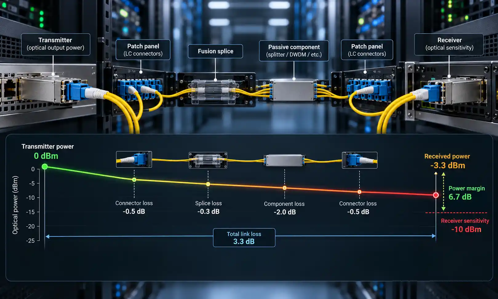
Remaining margin = available system budget − fiber loss − connector loss − splice loss − circulator loss − other passive loss − engineering margin
Use the maximum guaranteed insertion loss for each intended circulator path. Do not use a typical value when a worst-case value is available.
5. Specify Isolation and Directivity Separately
Isolation describes reverse leakage toward the previous port. Directivity describes skip-port leakage toward a non-sequential port. Both can affect source stability, receiver noise, and measurement accuracy.
6. Check Connectors, Power, and Environment
Record connector type, polish, pigtail length, jacket, continuous and peak power, operating temperature, storage temperature, package requirements, and cleaning method.
7. Define Factory and Incoming-Test Evidence
Specify the required test wavelength, port paths, limits, tester information, serial traceability, and electronic report format before issuing the purchase order.
Illustrative FBG Specification Template
The following is a procurement template, not a claim about a measured FOCC customer system.
| Field | Illustrative requirement |
|---|---|
| Architecture | Source at Port 1, FBG sensing fiber at Port 2, detector at Port 3 |
| Port type | Three-port quasi or incompletely circulated device is acceptable if only 1→2 and 2→3 are required |
| Wavelength range | Must cover the complete source and FBG reflection range |
| Fiber | Single-mode or PM fiber as required by the sensing architecture |
| Insertion loss | Maximum guaranteed value defined separately for 1→2 and 2→3 |
| Isolation | Minimum value defined for the unwanted reverse path |
| Directivity | Minimum value defined for source leakage into the detector path |
| Return loss | Minimum value defined at the required wavelength |
| Connector | APC or UPC selected to match the system without direct polish mismatch |
| Test report | Serial number, path map, wavelength, IL, isolation, directivity, RL where required, tester, date, and pass/fail limits |
Optical Circulator Installation and Acceptance Testing
Inspect, Clean, and Reinspect
Connector contamination can increase loss and reflection and can make a good circulator appear defective. Follow an inspect-clean-reinspect process before establishing references or connecting the device. FOCC's guide explains how to clean fiber optic connectors before testing.
Establish the Reference and Measure Intended-Path Loss
- Use a stable source at the required wavelength and a calibrated optical power meter.
- Establish the reference power with the approved reference cords and method.
- Insert the circulator in the intended path, such as 1→2.
- Record the output power and calculate the path loss.
- Repeat for 2→3 and for 3→1 only when that path is specified.
Insertion loss = reference power − measured output power
Use the same wavelength, launch condition, connector condition, and reference method stated by the acceptance plan. FOCC's guide to fiber optic power-meter testing provides additional instrument context.
Measure Isolation and Directivity
For isolation, launch light into the reverse direction being evaluated, such as Port 2, and measure leakage at the previous port, such as Port 1. For directivity, measure leakage at the skip port, such as Port 3 when launching into Port 1.
The source stability, detector noise floor, adapters, termination of unused ports, and total measurement dynamic range must be sufficient for the specified limit. A reading at the detector floor does not by itself prove the actual isolation value.
Verify Return Loss and PM Performance
Return loss requires an approved reflectance or return-loss method rather than inference from insertion loss. For a PM device, align the launch axis, confirm connector keying, and measure PER using the project method. Record the axis convention in the test report.
Minimum Acceptance Record
| Record item | Required information |
|---|---|
| Identification | Manufacturer, part number, serial number, port map, fiber, connector, and polish |
| Test conditions | Wavelength, source, meter, reference method, adapters, and environmental conditions |
| Intended paths | Measured IL and limit for every required path |
| Leakage paths | Isolation and directivity path, measured result, and detector floor |
| Reflection | Return loss result and method where required |
| PM performance | Axis orientation, keying accuracy, PER result, and limit where applicable |
| Traceability | Tester model, serial number, calibration status, operator, date, and electronic result file |
Common Problems and Troubleshooting
| Observed problem | Likely cause | Recommended check |
|---|---|---|
| Strong signal appears at the wrong output | Incorrect port map or a product numbering assumption | Verify the arrows and test each path independently |
| Insertion loss is high on every path | Contaminated connectors, polish mismatch, poor reference, or wrong wavelength | Inspect and clean, confirm APC/UPC, then repeat the reference |
| IL passes but receiver noise is high | Insufficient isolation or directivity | Measure the relevant leakage paths with adequate dynamic range |
| Results change when the input fiber moves | Polarization dependence or stressed fiber | Check PDL requirements and stabilize the launch condition |
| PM system shows low interference visibility | Axis misalignment, low PER, or incorrect connector keying | Verify launch axis, splice rotation, keying, and PER |
| Broadband source works only over part of its spectrum | Circulator bandwidth is too narrow or wavelength-dependent loss is excessive | Measure the spectral transfer behavior across the full source range |
| Detector saturates in a reflective system | Unexpected return power or insufficient attenuation | Calculate maximum return power and protect the receiver according to its data sheet |
FAQ
Q: Is an optical circulator the same as an optical isolator?
A: No. An isolator suppresses reverse-traveling light. A circulator redirects that light to another usable port.
Q: Does a fiber optic circulator amplify the signal?
A: No. It is a passive routing device and introduces insertion loss. Optical gain requires an amplifier.
Q: Can a circulator replace a WDM multiplexer?
A: No. A circulator routes mainly by propagation direction, while a WDM device separates or combines signals by wavelength.
Q: Can one circulator be used at both 1310 nm and 1550 nm?
A: Only when its guaranteed wavelength range and performance explicitly cover both regions. A nominal center wavelength is not enough.
Q: Does a three-port circulator always support Port 3 to Port 1?
A: No. That path may exist in a fully circulated unit but can be unavailable in a quasi or incompletely circulated design.
Q: What is the difference between isolation and directivity?
A: Isolation usually describes reverse leakage, such as 2→1. Directivity describes skip-port leakage, such as 1→3. They must be specified and measured separately.
Q: Can an optical circulator be used with multimode fiber?
A: Only when the device is specifically designed and qualified for the required multimode architecture. A standard single-mode circulator should not be treated as a multimode component.
Q: Which connector polish should be used?
A: Use the connector and polish defined by the complete system. APC can reduce interface reflection in suitable applications, but APC and UPC interfaces should not be directly mated.
Final Procurement Checklist
- Required port map and full or incompletely circulated operation
- Number of ports and package format
- Operating wavelength and complete bandwidth
- Single-mode, PM, multimode, or specialty fiber
- Maximum insertion loss for each intended path
- Minimum isolation and minimum directivity
- Minimum return loss
- Maximum PDL or minimum PER, where applicable
- Continuous and peak optical power limits
- Connector type, polish, keying, pigtail, and jacket
- Operating and storage environment
- Factory report, serial traceability, and incoming-test method
The correct fiber optic circulator is not selected by wavelength or port count alone. Start with the required signal paths, then match the bandwidth, fiber, polarization, path loss, isolation, directivity, return loss, optical power, connector system, environment, and test evidence.