When a high-speed MTP/MPO port fails, the first question is often not "which cable should I replace?" but "is the problem coming from the transceiver, the switch port, or the fiber link?"
A 24 fiber MTP female OM4 loopback cable is designed for this exact situation. By routing the optical signal from the transmitter side back to the receiver side, it allows engineers to verify transceiver and port performance without building a full end-to-end fiber link. For data centers, telecom labs and equipment manufacturers, this small test cable can reduce troubleshooting time, simplify port validation and help avoid unnecessary module replacement.
Why Transceiver and Port Testing Needs a Loopback Cable

Before a high-speed optical link is deployed, engineers need to confirm whether the transceiver, switch port, and signal path are working correctly. In many cases, a failed link does not immediately tell you where the problem is coming from. It may be caused by a faulty optical module, an abnormal port, incorrect cabling, contaminated connector end faces, or excessive insertion loss. A fiber optic loopback cable provides a simple and efficient way to isolate the problem. By routing the transmitted optical signal directly back to the receiver side of the same port, it allows the transceiver and equipment interface to perform a local self-test without connecting to a remote device.
For MTP/MPO-based high-density interfaces, this testing method is especially useful. A 24 fiber MTP female OM4 loopback cable can be used to verify whether the transmit and receive channels are functioning properly, check port connectivity, support transceiver production testing, and speed up field troubleshooting. During the test, the optical signal emitted from the module is returned through the internal fiber mapping of the loopback cable. Test instruments can then monitor both the transmitted power and the returned received power, helping engineers evaluate basic link performance before a full network connection is established.
The key performance indicators of a loopback cable include insertion loss, return loss, fiber mapping accuracy, connector end-face quality, and overall link integrity. For multimode loopback assemblies, low insertion loss and stable return loss are important because they reduce test uncertainty and help avoid false fault judgments. In practical data center, lab, and equipment manufacturing environments, loopback testing can shorten troubleshooting time, reduce unnecessary module replacement, and improve deployment reliability.
What is a 24-core MTP female connector OM4 loopback optical cable?
A 24 fiber MTP female OM4 loopback cable is a high-density multimode test cable designed for transceiver, switch port, and MTP/MPO interface verification. It is built with OM4 50/125µm multimode fiber and a 24-fiber MTP/MPO connector structure, allowing the transmitted optical signal to be routed back to the receiving channels within the same interface. This makes it a practical tool for local loopback testing without the need for a remot
MTP is a high-performance branded version of the MPO connector family and is widely used in high-density parallel optical applications. MTP/MPO connectors are generally available in male and female versions. An MTP does not have guide Mincludes two guide pins to help align the fiber array when two connectors are mated. Correct connector gender is important because the guide pins help maintain precise fiber core alignment and reduce the risk of excessive insertion loss during testing.
In a 24 fiber MTP OM4 loopback assembly, the internal fiber mapping is designed to return the Tx channels back to the corresponding Rx channels, enabling the port or transceiver to perform a self-test. Depending on the equipment interface, the product can be configured as an MTP female loopback assembly or customized with different gender combinations, mapping designs, housing structures, and cable lengths.
OM4 multimode fiber is suitable for high-speed short-reach optical testing because it offers higher bandwidth and stable performance at 850nm. According to typical OM4 specifications, the effective modal bandwidth at 850nm can reach ≥4700 MHz·km, while the attenuation is commonly controlled within multimode link requirements. For data center and lab environments, the loopback cable is usually supplied with an LSZH jacket and can be customized in common lengths such as 1m, 3m, 5m, 10m, or project-specific lengths.
A reliable MTP OM4 loopback cable should not only match the correct fiber count and connector gender, but also provide stable optical performance. Important quality factors include insertion loss, return loss, fiber mapping accuracy, connector end-face quality, and ferrule alignment. For professional transceiver and port testing, manufacturers often control typical insertion loss at a low level and provide test reports for IL, polarity or mapping, and end-face inspection to ensure consistent test results.
Why Choose a 24-Fiber MTP Loopback Cable Instead of a 12-Fiber Version?

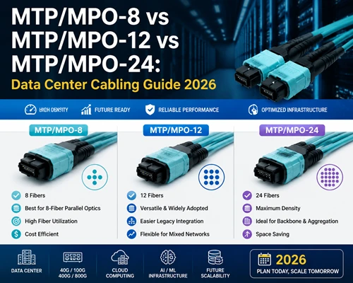
Both 12-fiber and 24-fiber MTP loopback cables are used for transceiver testing, port diagnostics, and high-density optical interface verification. However, they are not designed for the same testing density or equipment architecture. A 12-fiber MTP loopback cable is often sufficient for common SR4-based applications, while a 24-fiber MTP loopback cable is more suitable for higher-density parallel optics, multi-channel lab testing, production inspection, and selected high-speed transceiver platforms that require more fiber lanes.
| Comparison Item | 12-Fiber MTP Loopback Cable | 24-Fiber MTP Loopback Cable |
|---|---|---|
| Fiber Density | 12 fibers, commonly used for SR4-style parallel optics where 8 active fibers may be used | 24 fibers, offering higher lane density for multi-channel and high-density interface testing |
| Typical Equipment | Commonly used with 40G/100G modules such as QSFP+ and QSFP28 SR4 | Used for higher-density MTP/MPO ports, production testing, lab validation, and selected 100G/400G/800G test environments depending on interface design |
| Testing Efficiency | Suitable for standard port-level loopback testing | Allows more fiber channels to be tested in one assembly, improving testing throughput |
| Cost | Lower cost due to fewer fibers and simpler connector structure | Higher unit cost, but more efficient for dense multi-channel testing |
| Scalability | Suitable for existing 10G/40G/100G network maintenance and validation | Better suited for high-density network equipment, future expansion, and large-scale transceiver testing |
| Recommended Scenario | Enterprise networks, standard data centers, SR4 transceiver testing | Hyperscale data centers, equipment manufacturing, optical module labs, and high-density port validation |
Higher Channel Density and Interface Compatibility
The main advantage of a 24-fiber MTP loopback cable is its higher fiber density. Compared with a 12-fiber version, it provides twice the number of fiber paths in a single compact connector interface. This is useful when engineers need to test high-density MTP/MPO ports, multi-lane optical modules, or equipment platforms where more parallel channels must be verified at the same time.
For traditional 40G/100G SR4 links, a 12-fiber MTP loopback cable is often enough because only part of the fiber array is actively used for transmit and receive channels. In contrast, a 24-fiber MTP OM4 loopback cable is more suitable when the test environment requires higher lane density, more complex fiber mapping, or compatibility with selected high-speed transceiver interfaces. Before ordering, the exact module interface, fiber count, connector gender, and lane mapping should always be confirmed.
Improved Testing Efficiency
In production testing, laboratory validation, or large-scale data center maintenance, testing efficiency matters. A 24-fiber MTP loopback cable can return more optical channels within one assembly, reducing the need for repeated cable changes and manual reconnections.
This is especially valuable for optical module manufacturers, switch vendors, system integrators, and data center teams that need to test many ports or modules in a short time. Instead of testing fewer lanes per cycle, a 24-fiber loopback solution can improve testing throughput and help standardize the validation process.
Cost and Scalability
A 24-fiber MTP loopback cable usually costs more than a 12-fiber version because it uses more fibers and a higher-density connector structure. However, for high-speed and high-density testing environments, the cost should not be evaluated only by the unit price of the cable. The more important factors are testing efficiency, port compatibility, reduced setup time, and long-term scalability.
For customers who only need to test standard 40G/100G SR4 ports, a 12-fiber loopback cable may be the more economical choice. For customers working with high-density parallel optics, multi-channel MTP/MPO interfaces, or next-generation equipment validation, a 24-fiber OM4 loopback cable can provide better flexibility and reduce the need to frequently change test assemblies.
Typical Applications in Data Centers and Laboratories
In optical transceiver production testing, the loopback cable can be inserted into the optical module for automated inspection: the optical signal output from the transmitter is returned to the receiver side of the module through the loopback cable, while test instruments or automated test equipment (ATE) record the bit error rate and received optical power, completing verification of the module's transmit and receive performance. SpringOptical case references indicate that using MPO loopback modules for 400G switch acceptance testing in data center environments can save about 30% of testing time.
Testing steps:
- Clean the port and the end face of the loopback cable in accordance with IEC 61300-3-35 requirements.
- Insert the 24-fiber MTP female loopback cable into the port under test, ensuring that the guide pin alignment is correct and the connection is secure.
- Start the optical module self-test or external test equipment, such as an optical signal generator, bit error rate tester, OTDR, or other instruments.
- Collect test data: measure the received optical power after loopback, bit error rate (BER), jitter, and other performance indicators.
- If required, use an optical loss test set (OLTS) or OTDR together with the loopback test to perform auxiliary testing on other link sections.
Notes and troubleshooting: Before testing, confirm that the polarity of the loopback cable is correct and that there is no fiber mapping mismatch. Common issues include contaminated end faces, broken fibers, or connector damage. If there is no response during testing, first replace the loopback cable or port module with a known-good unit to locate the fault. If insertion loss is abnormally high, check whether the fiber end face has scratches or whether the cable has bending damage. If only some channels have no signal, verify whether the polarity mapping is consistent. Loopback testing can also be used together with standard patch cord testing to further isolate whether the problem comes from the loopback cable or from the port itself.
Looking for a manufacturer of 24-core MTP female OM4 loopback optical cables?
FOCC can supply 24 fiber MTP female OM4 loopback cables for transceiver testing, MTP/MPO port diagnostics and high-density data center maintenance. Configurations can be customized according to connector gender, fiber mapping, jacket material, length, labeling and packaging requirements. Each assembly can be tested for insertion loss, polarity/mapping and connector end-face quality before shipment.