AI Data Center Upgrades-Why Do Physical Layer Details Matter More?
With the massive explosion of large language models and AI compute clusters, AI data centers are driving an unprecedented surge in high-speed optical interconnect demands. As network architectures rapidly evolve toward 800G and even 1.6T Ethernet, the optical power budget allocated for the physical layer is being compressed to its absolute physical limits. Under these tight conditions, link budget margins, end-face cleanliness, and long-term connection stability are receiving more critical focus than ever before.
From a macro perspective, a short fiber pigtail is not a core backbone component of a 1.6T main link. However, it plays an irreplaceable role in precision link testing, high-density ODF (Optical Distribution Frame) fusion splicing, routine fiber termination, and high-frequency network maintenance. Any minute instance of excessive insertion loss or back-reflection can turn into a hidden catalyst for network instability or link flapping within a massive compute cluster.
Which AI-Related Scenarios Suit FC/APC Pigtails?
In high-performance optical network deployments, defining the exact application boundaries of each component is essential for stability. As a highly stable mechanical connection component, the FC/APC single-mode pigtail is specifically engineered for the following AI-related and
precision foundational network environments:
- Precision Testing Instrument Interfaces: Perfectly matches the external reference interfaces of continuous-wave (CW) lasers, high-precision optical power meters, and Optical Time Domain Reflectometers (OTDRs), providing exceptional repeatability and a high mating lifecycle.
- ODF Patch Panel Fusion Splicing: Explicitly designed for the confined spaces inside high-density ODF cabinets, splice trays, and fiber distribution units, enabling a seamless transition from backbone fiber cables to equipment ports.
- Low-Reflection Single-Mode Links Between Devices: Deployed in core switch rooms or central offices for single-mode fiber patch links that are highly sensitive to back-reflection noise.
- CATV / PON / Access Network Testing: Effectively eliminates back-reflection noise in high-power multi-channel analog/digital video streaming networks and Passive Optical Networks (PON), ensuring baseline system stability.
- Edge Server Rooms and Campus Networks: Well-suited for modular edge data center terminations and the cross-connection of fiber backbones across enterprise-level AI campus networks.
focc Manufacturing Team Special Reminder: This product is NOT intended for chip-to-chip interconnects inside GPUs, is NOT used as a main link direct patch cord for 1.6T optical modules, does NOT involve internal routing for CPO (Co-Packaged Optics) main connections, and is NOT recommended for ultra-compact board-level routing inside high-density liquid-cooled servers. Please ensure each optical component is deployed strictly within its engineered boundaries to maximize physical layer performance.
Why Does the APC End-Face Help Reduce Reflection?
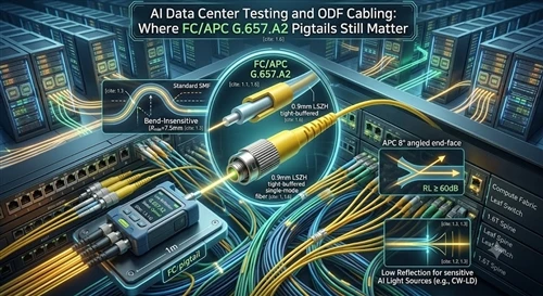
In high-speed or high-power optical networks, Return Loss (RL) serves as a defining metric for physical layer connection quality. The classic FC connector featured on this pigtail uses a high-precision ceramic ferrule with an APC (Angle Physical Contact, 8° Angled) ultra-fine machine-polished end-face.
Unlike traditional flat UPC (Ultra Physical Contact) polishing, the 8° angled design forces the vast majority of back-reflected light generated at the connection interface to reflect away from the fiber core and escape harmlessly into the cladding. This structural characteristic allows the link to reliably achieve a telecom-grade return loss specification of ≥ 60 dB. In volume manufacturing, we strictly verify this high-return-loss performance through 100% factory optical testing to prevent reflection noise from interfering with sensitive laser sources.
G.657.A2 Bend-Insensitive Fiber Is Ideal for Compact Spaces
Physical space inside modern data centers comes at a premium. The internal confines of ODF cabinets, high-density splice trays, termination boxes, and residential weak-current enclosures are notoriously cramped and limited.
To resolve this spatial anxiety, this pigtail is built with premium G.657.A2 bend-insensitive single-mode fiber (core diameter 8.3 μm, cladding outer diameter 125 μm). The physical properties of this fiber make it highly resistant to radiation losses caused by tight bends, meaning it effectively suppresses macro-bending attenuation. During high-density fiber management and routing, it guarantees superb signal integrity. The exact allowable bending radius and precise technical metrics strictly adhere to our official product datasheet, ensuring stress-free cable routing inside crowded enclosures.
The 0.9mm LSZH Structure Fits Perfect for Fusion Splicing and Indoor Cabling
The external structural engineering of a fiber cable directly dictates its field installation efficiency and environmental safety characteristics:
- 0.9mm Tight-Buffered Configuration: The cable utilizes a typical indoor simplex tight-buffered format with a nominal outer diameter of 0.9 ± 0.05 mm. This thin structure is incredibly lightweight and flexible, and the tight buffer layer offers smooth, consistent stripability. This allows field technicians to perform fast, high-quality heat fusion splicing or mechanical cold splicing within cramped termination spaces.
- LSZH Low Smoke Zero Halogen Outer Jacket: The jacket is extruded from a halogen-free, flame-retardant compound heavily filled with inorganic flame retardants (such as aluminum hydroxide and magnesium hydroxide). In the event of extreme high-temperature fires in a server room, it emits only a negligible amount of faint smoke and absolutely zero toxic, corrosive halogen gases (like chlorine or bromine). This not only protects personnel during evacuation but also prevents acidic mist from depositing onto and permanently destroying multi-million-dollar server chips.
💡 Field Installation Tip: While 0.9mm tight-buffered fiber offers great convenience for indoor routing and splice trays, it is NOT the same as an outdoor high-tensile cable. Because it lacks heavy aramid strength members (Kevlar) and rugged outer armoring, its tensile strength is physically limited. It is NOT suitable for high-force pulling or unprotected open-air routing without protective conduits or cable trays. During installation and non-static handling, ensure the bending radius remains at least 30 times the cable diameter to prevent micro-bending losses or structural damage.
Which Parameters Should Be Confirmed When Procuring This Type of Pigtail?
To help system integrators and technical procurement teams conduct smooth compatibility evaluations, we recommend cross-checking the following structured parameters during volume purchasing or project bidding:
| Procurement Item | Recommended Confirmation Content |
| Connector Type | FC/APC (with heavy-duty M8 × 0.75 mm metal threaded locking mechanism and anti-rotation positioning key) |
| Fiber Core Type | G.657.A2 single-mode fiber (8.3 μm core diameter, 125 μm cladding diameter) |
| Cable Outer Diameter | 0.9 mm tight-buffered structure |
| Jacket Material | LSZH (Low Smoke Zero Halogen, flame-retardant and eco-friendly compound) |
| Cable Length | 1 meter standard, or flexibly customized based on network topology designs |
| Insertion Loss (IL) | Confirm if individual actual test values are provided per patch cord (typical target ≤ 0.20 dB) |
| Return Loss (RL) | Confirm support for APC process with verified actual test return loss ≥ 60 dB (per IEC 61300-3-6) |
| End-Face Quality | Confirm if 100% scratch-free and contamination-free inspections are conducted per IEC 61300-3-35 |
| End-Face Geometry | Confirm if 3D geometric interferometer parameters (Radius of Curvature, Apex Offset, Fiber Height) are monitored |
| Commercial Packaging | Individually sealed anti-static bag packaging, complete with an exclusive data label and traceable test report |
| Compliance & Certifications | Verify third-party documentation for RoHS, REACH environmental compliance, and CPR building material flame-retardant ratings |
What Support Can FOCC Provide?
As a direct source manufacturer dedicated to premium fiber optic interconnect solutions for many years, FOCC safeguards your network infrastructure with telecom-grade quality control and deep technical expertise. For high-standard data center builds and enterprise telecom projects, we offer comprehensive manufacturing-level and customized support:
- Comprehensive Connector Portfolios: Full customization capabilities for FC/APC, SC/APC, LC/APC, E2000/APC, and other high-precision connector variants to match any equipment patch panel configuration.
- Flexible Line Structures: Availability of 0.9mm tight-buffered pigtails, as well as 2.0mm and 3.0mm outer diameter ruggedized cordage configurations, wrapped in either premium flame-retardant LSZH or standard PVC jacket types.
- Tailored Lengths and Specifications: Beyond our standard 1-meter configurations, we easily accommodate custom lengths (such as 1.5m, 2m, 5m, etc.) tailored to your exact cabinet cable management layouts, minimizing excess cable slack.
- 100% Factory-Level Testing: Every single item leaving our factory undergoes a strict dual-inspection workflow: an industrial-grade 3D geometric interferometer test and a 400x electronic microscope end-face verification, with an individual IL/RL test report attached for full data traceability.
- OEM Private Labeling and Packaging: Customized OEM/ODM commercial packaging layouts and dedicated barcode tracking labels to facilitate effortless inventory audits and digital warehouse management during volume procurement.
In the AI compute era, where networks are being pushed to their ultimate physical constraints, every short physical connection counts. Click the official product link below to download our exhaustive technical whitepapers, or reach out directly to our engineering experts for customized quotes and sample evaluations!
FAQ
Q: Since single-mode fiber has a longer transmission distance and better performance, can I directly plug single-mode optical modules in the data center into multimode fiber?
A: Absolutely not. The core diameter of a single-mode optical module is typically only 8.3 μm, while the core diameter of multimode fiber is typically 50 μm or 62.5 μm. Connecting a single-mode optical module to multimode fiber will result in significant insertion loss due to the severe core diameter mismatch, leading to severe packet loss or even complete network malfunction. During data center cabling and testing, optical modules and patch cords/pigeons must be perfectly matched between single-mode and multimode.
Q: The 0.9mm narrow diameter structure is very convenient for fusion splicing, but can it be used for unprotected patch cord installation?
A: Absolutely not. The 0.9mm tight-buffered structure (GJFJV) is designed for high-density termination and fusion splicing of fiber coils. It is extremely lightweight and flexible, and the tight-buffered layer is very easy to peel off. However, it must be clear that it lacks an outer aramid reinforcement (Kevlar) and heavy armor protection. If directly exposed to the outside of the equipment room and subjected to strong pulling or high-strength cable ties, the fiber can easily suffer physical damage or irreversible micro-bending loss. During installation, cable trays must be used for protection, and the bending radius in a non-static state should not be less than 30 times the outer diameter.
Q: In a sea of colorful fiber optic cables, what is the practical management value of the internationally standard "yellow sheath"?
A: In high-density cabling systems with thousands of interwoven cores in data centers, yellow is the internationally recognized official identification color for single-mode fiber. It provides strong visual separation from multimode OM4 (magenta) or OM3 (light blue) patch cords. This allows maintenance personnel to easily identify specific single-mode links during routine patch cord changes or high-frequency testing, completely preventing network incidents caused by human error in disconnecting adjacent fibers from a visual management perspective.