Polarization-maintaining fiber, often called PM fiber or HiBi (high-birefringence) fiber, is a specialty single-mode fiber engineered to preserve the linear polarization state of light along a defined axis. It is the fiber of choice whenever a system's performance depends on a stable, known polarization state - fiber optic gyroscopes, interferometric sensors, coherent detection, lithium niobate modulators, narrow-linewidth fiber lasers, quantum communication links, and OCT imaging engines all rely on it.
Unlike standard single-mode fiber, PM fiber does not try to eliminate polarization effects. It deliberately introduces strong, stable birefringence so that two orthogonal polarization modes are decoupled. When linearly polarized light is launched along one of the fiber's principal axes, it stays there - even under bending, vibration, and temperature drift that would scramble polarization in ordinary single-mode patch cords.
This guide explains how PM fiber works, the trade-offs between PANDA and bow-tie designs, how to compare PER specifications honestly, when PM fiber is actually necessary (and when it isn't), and what engineers should verify before ordering a PM patch cable or assembly.
What Is Polarization-Maintaining Fiber?
A polarization-maintaining fiber is a single-mode optical fiber with intentionally engineered internal stress or geometry that creates a large, stable difference in refractive index between two orthogonal polarization axes. This difference - birefringence - keeps the two polarization modes from exchanging energy.
The fiber is known by several names in industry literature and datasheets: PM fiber, polarization-preserving fiber, polarization-maintaining single-mode fiber, and HiBi fiber. The last term, used in academic work, captures what makes PM fiber different from ordinary single-mode fiber: not the number of guided spatial modes, but the magnitude of the birefringence.
In standard single-mode fiber, residual birefringence is small and unpredictable. Bend a coil, change the ambient temperature, or twist the cable, and the output polarization state drifts. For most data center links this does not matter - receivers integrate over polarization or use polarization-diversity optics. For systems where polarization carries phase, amplitude, or measurement information, that drift is the failure mode PM fiber is built to eliminate.
Why Polarization Stability Matters in Optical Systems
The electric field of light oscillates in a particular direction; that direction is its polarization. A long list of optical devices respond differently to different polarization states:
- Lithium niobate (LiNbO₃) Mach-Zehnder modulators are intrinsically polarization-dependent. Drift in input polarization shows up directly as modulation-depth and extinction-ratio degradation on the transmitter output.
- Fiber optic gyroscopes (FOG) measure rotation through the Sagnac effect. Polarization coupling between the two counter-propagating beams introduces non-reciprocal phase errors that the loop cannot distinguish from real rotation, producing measurable bias drift.
- Coherent optical receivers mix the incoming signal with a local oscillator. Although coherent transceivers use polarization-diversity hybrids, the local oscillator path itself often needs a stable polarization reference, and PM fiber is standard between the LO laser and the hybrid.
- Interferometric sensors and OCT engines rely on consistent fringe visibility; uncorrelated polarization drift in the two arms collapses the interference contrast.
In all of these, replacing PM fiber with standard SMF doesn't break the link - it makes performance unrepeatable. That's the harder failure to debug, which is why engineers specify PM fiber from the start rather than retrofit it later.
How PM Fiber Actually Works

Birefringence: The Core Mechanism
Birefringence means a material has two different refractive indices for two orthogonal polarization directions. Light polarized along one axis travels at a slightly different phase velocity than light along the other. The difference is small - typically a few parts in 10⁴ - but it is large compared to the random, stress-induced birefringence of ordinary fiber, and that's what matters.
Energy coupling between two modes requires them to be phase-matched over some length. The stronger the birefringence, the more rapidly the two modes accumulate phase difference, and the harder it becomes for environmental perturbations (bends, twists, temperature gradients) to couple energy from one to the other. A useful figure of merit here is the beat length LB = λ / Δn, typically 2–5 mm for high-quality PANDA fiber at 1550 nm. Short beat length means strong polarization holding.
Fast Axis and Slow Axis
PM fiber has two principal polarization axes, conventionally labeled the fast axis (lower refractive index, higher phase velocity) and the slow axis (higher refractive index, lower phase velocity). By convention in most commercial PM fiber assemblies, linearly polarized light is launched along the slow axis, and connector keys are oriented to the slow axis unless otherwise specified.
This convention matters in procurement. If your transmitter expects slow-axis output but the assembly is built to fast-axis convention, the launch into the next stage will be 90° rotated. Always confirm axis convention in the datasheet - not all manufacturers are explicit about it, and "slow axis aligned to key" is the safest standard.
Launch Alignment and Extinction Ratio
PM fiber only delivers polarization stability if input light is aligned with a principal axis. If the launch is rotated by an angle θ relative to the slow axis, a fraction sin²(θ) of the power couples into the orthogonal axis. From that point on, the two components propagate with different phase velocities and the output state depends on length, temperature, and wavelength - exactly what PM fiber is meant to prevent.
The polarization extinction ratio (PER), expressed in dB, measures how much of the output power remains in the intended polarization versus the orthogonal one. Good commercial PM patch cables achieve 25–30 dB PER under controlled launch and quiet mechanical conditions; high-performance assemblies for sensing applications push 35 dB and above. But PER is a system measurement, not a fiber-only specification. The same fiber will show 30 dB PER on a stable optical bench and 18 dB after being routed around a chassis corner with a pinched bend.
PANDA, Bow-Tie, and Elliptical-Core: Which PM Fiber Design Fits Where?
All commercial PM fiber designs work by breaking the circular symmetry of the core's stress field. The differences come down to how that asymmetry is built in, and what that costs in PER, attenuation, and price.
PANDA PM Fiber
PANDA (Polarization-maintaining AND Absorption-reducing) fiber places two circular stress-applying parts (SAPs) on either side of the core, doped with boron to have a thermal expansion coefficient different from the silica cladding. When the preform cools after drawing, the SAPs apply asymmetric stress that creates strong, stable birefringence.
PANDA dominates the commercial PM market for three reasons: the geometry is well-suited to high-volume production, the cleaving and splicing behavior is predictable, and the design works across the standard telecom and sensing wavelength windows (typically optimized for 780 nm, 850 nm, 980 nm, 1060 nm, 1310 nm, and 1550 nm variants). For most modulator-pigtail, FOG, and coherent applications, PANDA is the default.

Bow-Tie PM Fiber
Bow-tie fiber uses two stress regions shaped like wedges or sectors that meet near the core, producing higher peak stress than PANDA for the same fiber diameter. This typically gives shorter beat lengths and higher inherent PER, which is why bow-tie is often preferred in high-end sensing - gyroscopes for navigation-grade inertial measurement units, hydrophone arrays, and Faraday-effect current sensors.
The trade-off is that bow-tie geometry is harder to splice consistently and is offered by fewer suppliers, so unit cost and lead times can be higher.
Elliptical-Core and Photonic-Crystal PM Fiber
Some PM fibers use a non-circular core (form birefringence) or a microstructured air-hole cladding (photonic crystal fiber) instead of stress elements. These specialty designs serve applications where stress-rod fibers struggle: high-power delivery where SAPs limit damage threshold, unusual wavelengths in the mid-IR or visible, or systems that need very low bend-induced birefringence change. For typical industrial and telecom buyers, PANDA and bow-tie cover almost every requirement.
PM Fiber vs Standard Single-Mode Fiber vs Polarizing Fiber
These three fiber types are routinely confused in purchasing conversations. They are not interchangeable.
- Standard single-mode fiber guides one spatial mode with low loss. Polarization is preserved on millisecond timescales but drifts over seconds to minutes due to thermal and mechanical changes. Suitable for everything from FTTH drop cables to data center interconnects, but unsuitable wherever a downstream component depends on a fixed polarization state.
- Polarization-maintaining fiber guides one spatial mode and preserves a linearly polarized state when light is properly launched. Both polarization axes are transmitted with low loss; the fiber's job is to keep them from mixing.
- Polarizing (PZ) fiber guides one spatial mode but actively attenuates one polarization. The unwanted axis sees high loss (often 30 dB/m or more), so the output is single-polarization regardless of input. Used where the system must reject one polarization, not preserve both.
The decision logic: if your problem is "polarization keeps drifting," choose PM fiber. If your problem is "I have polarized noise I need to suppress at the output," choose polarizing fiber. If neither problem exists, standard SMF is cheaper, easier to splice, and easier to source.
When Do You Actually Need PM Fiber?
This is the question that gets misanswered most often in BOM reviews. PM fiber is two to five times the cost of standard SMF and significantly harder to splice and terminate. Specifying it where it isn't needed is wasted budget; specifying SMF where PM is required is a debugging nightmare. Use the following as a first-pass decision matrix:
- Laser source to LiNbO₃ external modulator: PM fiber is essentially required. Modulator efficiency is polarization-dependent and the input must be aligned to the device's TE axis.
- Fiber optic gyroscope / Sagnac interferometer: PM fiber throughout the sensing coil. Polarization non-reciprocity is one of the dominant FOG bias error sources.
- Narrow-linewidth laser to acousto-optic modulator or frequency shifter: Usually PM fiber - diffraction efficiency depends on input polarization.
- Coherent transceiver internal LO path: PM fiber from local oscillator laser to the optical hybrid is standard.
- OCT or interferometric biomedical imaging: PM fiber maintains fringe contrast; without it, polarization drift modulates image quality.
- Standard data communication / Ethernet / FTTH: Standard OS2 single-mode fiber is sufficient. Receivers do not care about input polarization.
- Long-haul DWDM transmission: Standard SMF. Modern coherent DSP corrects for polarization rotation in real time.
- Single short PM jumper in an otherwise SMF system: Almost certainly pointless. Polarization scrambles before and after the PM segment unless the entire optical path is PM-aware.
The last point is worth emphasizing because it is the most common procurement mistake. PM fiber only helps if the system upstream can deliver aligned linear polarization to the fiber input and the system downstream requires that polarization state. A single PM jumper sandwiched between SMF segments adds cost without function.

How to Choose a PM Fiber or PM Patch Cable
PM fiber selection is a multi-parameter problem. The following checklist reflects what engineers should verify on the supplier's datasheet before placing an order.
1. Operating Wavelength and Cutoff
PM fiber is wavelength-specific. A fiber designed for 1550 nm operation will not run single-mode at 980 nm - it will guide higher-order modes and PER will collapse. Confirm the operating wavelength against the fiber's cutoff wavelength (which should be at least 100 nm below your shortest operating wavelength). Common designs include PM630 (visible/780 nm), PM980 (980 nm pump lasers), PM1060 (Yb fiber lasers), PM1310, and PM1550.
Mode field diameter (MFD) matters when splicing PM fiber to a different fiber type - a large MFD mismatch produces both splice loss and reduced PER.
2. PER Target - and Test Conditions
This is where datasheet comparison goes wrong most often. Vendor A may quote 25 dB PER at 1550 nm and Vendor B may quote 30 dB PER, but if they tested under different launch conditions, connector types, fiber lengths, and ambient temperatures, the numbers are not comparable. Before comparing PER values, verify:
- Test wavelength
- Launch method (free-space polarizer vs. PM input pigtail)
- Connector type and polish (FC/APC tends to give cleaner PER readings than FC/PC due to back-reflection effects)
- Axis alignment method and tolerance during connectorization
- Fiber length and whether the test was performed on a coiled or straight sample
- Temperature during measurement
A 25 dB PER spec tested with proper launch alignment on a 2 m cable in a stable environment can be a better real-world product than a 30 dB spec measured under unstated conditions.
3. Connector Type and Key Orientation
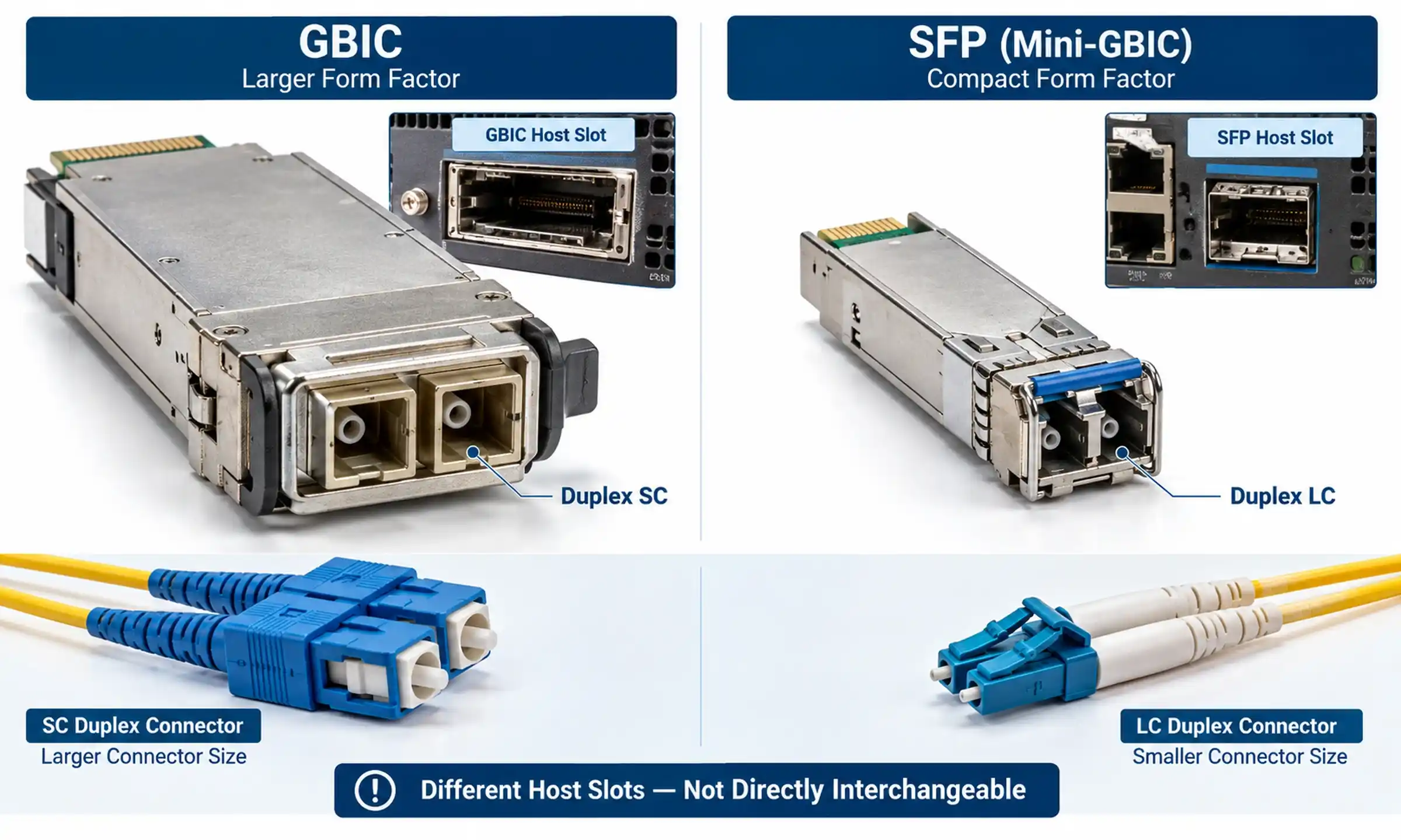
PM connectors look identical to standard connectors but include a defined axis-to-key relationship. Standard options include FC/PC, FC/APC, SC/APC, and LC/APC for PM applications, with FC/APC being most common in lab and sensing environments due to its mechanical stability and low back-reflection. APC is generally preferred over PC for laser-based systems because back-reflections can destabilize narrow-linewidth sources.
When ordering PM patch cables, confirm with your supplier: which axis is keyed (slow axis is the convention), what the angular alignment tolerance is (typically ±1° to ±3°), and whether the same convention is applied consistently across both connectors of the assembly.
4. Insertion Loss and Return Loss
Insertion loss for a quality PM patch cable should be ≤0.5 dB per connector pair. Return loss for APC-terminated PM cables should be ≥60 dB; for PC connectors, ≥40 dB. These numbers matter more in laser systems than in sensing systems - for an FOG, the dominant concern is PER, not 0.1 dB of extra IL.
5. Bend Radius and Mechanical Handling
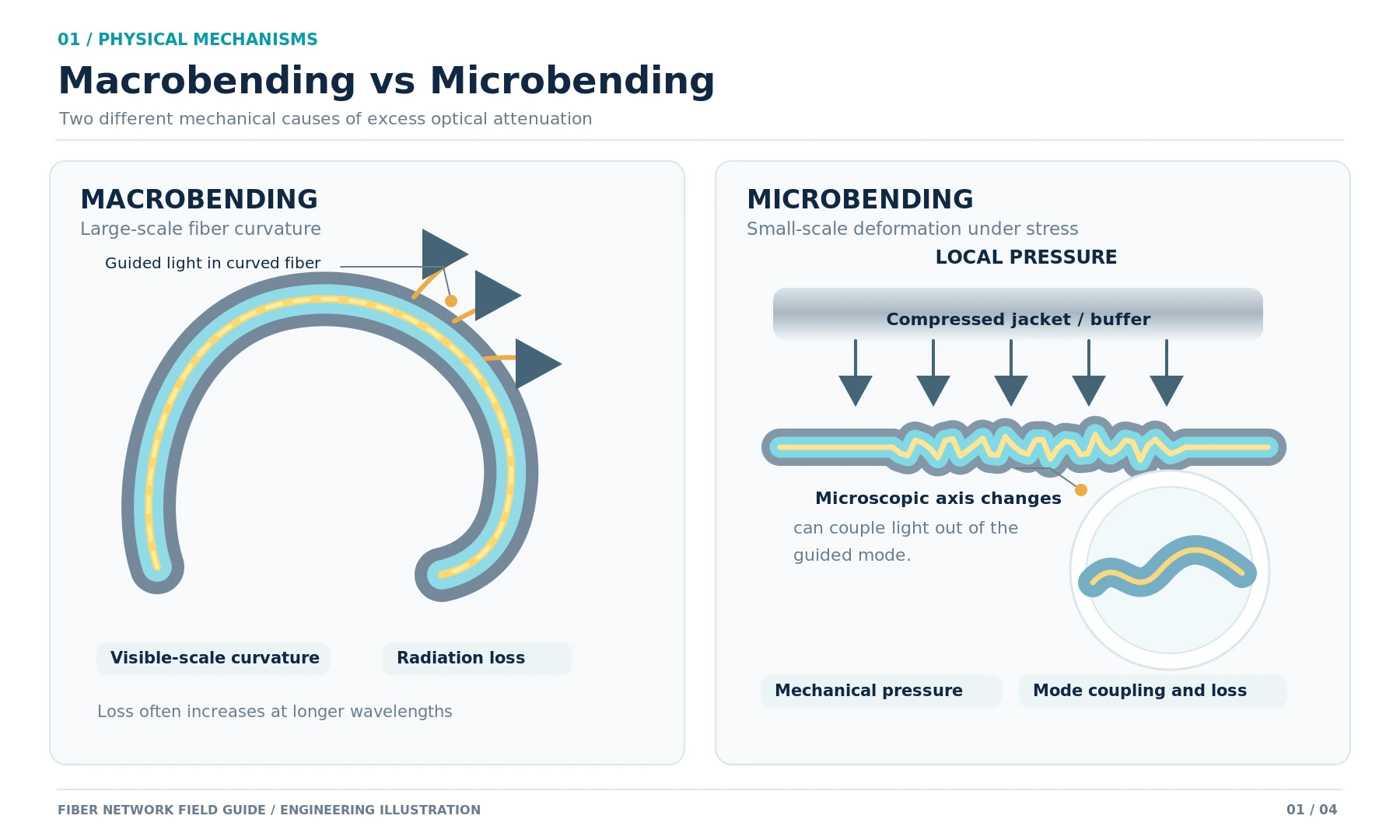
PM fiber's birefringence comes from internal stress, so external stress directly degrades performance. Stay well above the manufacturer's minimum bend radius (typically 30 mm for short-term and 60 mm long-term in standard PM fiber), avoid clamping near connectors, and never route PM patch cables through tight cable management with kinked sections. A perfect 30 dB PER cable will read 15 dB after one careless installation.
6. Splicing Requirements
Splicing PM fiber requires a fusion splicer with active axis alignment capability - typical mass-market splicers cannot align stress-rod orientation reliably enough to maintain PER across the splice. Expect 0.05–0.15 dB splice loss and a PER degradation of 0.5–2 dB per splice with a properly tuned PM-capable splicer. If your application requires splicing PM to standard SMF, expect the splice to behave as a polarization scrambler - only one of the two PM modes survives intact.
Common PM Fiber Mistakes and What They Actually Cost
Treating PM Fiber as a Drop-In SMF Replacement
The most expensive mistake. PM fiber only delivers value when the entire system is designed around polarization control: the source must produce linearly polarized light, the launch must be axis-aligned, and the receiver or downstream device must care about the output polarization. Drop one PM patch cable into an SMF system and you've spent extra money for zero benefit.
Ignoring Connector Key Orientation Across Assemblies
If a system uses three PM jumpers between source and modulator, all three must use the same axis convention. A 90° offset in any connector pair rotates the polarization, and the modulator sees a 90° error - for a typical LiNbO₃ modulator this drops the modulated output to nearly zero.
Overbending Near Connectors
The boot of a PM connector concentrates stress at the fiber's most sensitive location. A bend kink within 50 mm of the connector can drop PER by 5–10 dB even if the bend radius elsewhere in the cable is generous. Use 30 mm or larger bend protection at every PM connector.
Comparing PER Across Vendors Without Test Conditions
Already covered above, but worth repeating because it's a recurring purchasing failure. Insist on test condition disclosure or perform incoming inspection PER tests under your own controlled launch.
Buying "PM Compatible" Components That Aren't
Standard fiber couplers, splitters, and isolators are not PM unless explicitly built as PM-rated devices. A PM patch cable feeding a non-PM 1×2 splitter destroys polarization at the splitter - the rest of the PM optical path is wasted. When building a PM system, verify every passive component is PM-rated and specify its axis convention.
FAQ: PM Fiber Selection and Use
What is a good PER value for a PM fiber patch cable?
For general commercial use, 22–25 dB PER is acceptable. For modulator pigtails, target 25–28 dB. For high-end sensing (gyroscopes, interferometric current sensors), specify 28–35 dB and verify under controlled launch conditions. A PER above 35 dB on a connectorized patch cable is exceptional and usually requires controlled handling.
Should PM fiber be aligned to the slow axis or the fast axis?
Slow axis alignment is the industry convention for connector keying and most product datasheets assume slow-axis launch. Fast-axis assemblies exist for specific applications (some laser designs) but should be explicitly called out in the order. When in doubt, confirm in writing with the supplier.
Can PM fiber be spliced to standard single-mode fiber?
Yes, but the splice acts as a polarization scrambler - only the launched-axis component continues to behave as polarization-maintained on the PM side; on the SMF side, polarization will drift normally. Use this for terminating a PM section into an SMF link (e.g., when launching into a measurement instrument), not for extending PM behavior across the splice.
What happens if PM fiber is bent too tightly?
Bend-induced stress couples energy between the two polarization axes and reduces PER. Mild over-bending produces gradual PER degradation that may recover when the bend is released; severe or repeated tight bends can cause permanent stress modification in the fiber, particularly near connectors. Always honor the manufacturer's minimum bend radius.
How do I specify PM connector key orientation when ordering?
State: (1) which axis (slow or fast - almost always slow), (2) which connector(s) on the assembly the convention applies to (typically both ends, same convention), and (3) the angular tolerance (e.g., ±2°). Reputable suppliers will confirm this on the order acknowledgment.
Is PM fiber the same as single-mode fiber?
PM fiber is a subset of single-mode fiber. All commercial PM fibers are single-mode at their design wavelength, but not all single-mode fibers are polarization-maintaining. The "single-mode" classification refers to the number of spatial modes; "polarization-maintaining" describes additional birefringence engineering.
Why does PM fiber cost more than standard fiber?
Preform fabrication is more complex (stress rods must be precisely placed before drawing), drawing tolerances are tighter, and connectorization requires axis-aligned polishing on specialized equipment. PM splicing requires more expensive splicers and trained operators. The cost premium typically runs 2–5× standard SMF for the fiber itself, with finished PM patch cable assemblies priced significantly above standard fiber patch assemblies.
Can PM fiber be used for long-distance telecom transmission?
Technically yes, but it isn't done in practice. Standard SMF combined with coherent DSP handles polarization recovery in software at far lower system cost. PM fiber for long-haul transmission would multiply cable, connector, and splicing costs without commercial benefit.
Engineering Summary: When to Specify PM Fiber
PM fiber is the right choice when three conditions are simultaneously true: the optical source produces linearly polarized light, the receiving device or downstream component is polarization-sensitive, and the entire optical path between them is PM-rated and axis-aligned. It is the wrong choice when any of those conditions break down - a single PM jumper between two SMF segments is wasted budget, and a PM source feeding a non-PM splitter is wasted source.
When specifying PM fiber assemblies, treat PER as a system parameter rather than a fiber parameter. Verify the test conditions behind every datasheet number, confirm connector axis convention in writing, design the cable routing to honor bend radius near connectors, and ensure every passive component in the optical chain is PM-rated. Get those four things right and PM fiber delivers exactly what it promises: a polarization state that arrives at the receiver in the same orientation it left the source, regardless of what the environment is doing to the cable in between.
For deeper technical reference on stress-rod fiber design and PER measurement methodology, manufacturer datasheets from Thorlabs PM fiber documentation and the original research on PANDA fiber by Hosaka et al. remain the standard references. For PM patch cable, pigtail, and coupler procurement, our polarization-maintaining product series covers FC, SC, and LC connector variants across common wavelength bands, with PER testing performed under disclosed launch conditions.