When you compare OTDR vs light source and power meter testing, the right choice depends on what you need to prove about the fiber link. The two instruments answer different questions, and on most professional projects you will use both at different stages.
Use a light source and power meter - or an optical loss test set (OLTS) - when you need the total end-to-end insertion loss of a link, for example to confirm it meets a loss budget before handover. Use an OTDR when you need to know where something is happening along the fiber: a bad connector, a high-loss splice, a tight bend, a break, an unexpected reflection, or an unknown patch point.
LSPM/OLTS proves the link passes; an OTDR helps you understand and locate what is inside it. The sections below break down what each tool measures, how to choose between OTDR, LSPM, and OLTS, and how the two fit into one acceptance-and-troubleshooting workflow.

OTDR vs Light Source and Power Meter (LSPM/OLTS)
A light source and power meter measures how much optical power is lost from one end of the link to the other - a single, direct number for total loss. An OTDR sends light pulses into the fiber, analyses the reflected and backscattered light, and produces a trace that maps events along the route.
| Testing need | Better tool | Why |
|---|---|---|
| Measure total insertion loss | Light source and power meter / OLTS | Direct end-to-end loss measurement against the loss budget |
| Certify installed cabling (Tier 1 / basic) | OLTS / LSPM | The recognised method for attenuation, length, and polarity |
| Locate a fault or break | OTDR | Shows the distance to the event |
| Find a bad splice or connector location | OTDR | Identifies and positions individual events |
| Investigate reflectance problems | OTDR | Shows reflective events and where they are |
| Fast pass/fail across many links | OLTS | Usually quicker for acceptance of large counts |
| A link that passes loss but performs poorly | OTDR | Reveals hidden reflectance or event-level issues |
| Document high-value or complex routes | Both | Total loss plus an event-level baseline trace |
What Does a Light Source and Power Meter (LSPM) Measure?
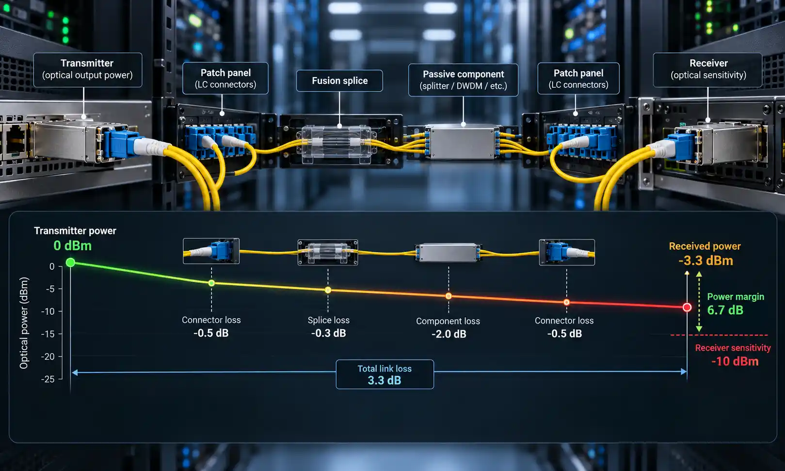
A light source and power meter set, often shortened to LSPM, uses two instruments. The light source launches a stable optical signal into one end of the fiber, and the power meter reads the received power at the other end. The result is shown as loss in decibels (dB) or received power in dBm.

It Measures End-to-End Insertion Loss
The core question an LSPM answers is simple: how much optical power does the full link lose? Every connector, splice, bend, adapter, and length of fiber adds loss, and if the total exceeds the allowed link budget the network may not run reliably. The accepted reference method tests the cable plant with a stable source and an optical power meter, measuring the difference in power when the link is inserted into the setup.
LSPM vs OLTS: What Is the Difference?
People often use "LSPM" and "OLTS" interchangeably, but there is a practical distinction. A basic LSPM is typically a separate handheld source plus a separate power meter, read manually. An optical loss test set (OLTS) is a more capable, often two-ended, automated version: it adds pass/fail limits, dual-wavelength testing, bidirectional measurement, length and polarity checks, and report generation. For certifying many links quickly, an OLTS or an automated insertion loss tester saves significant field time over a manual source-and-meter pair, while measuring the same thing - total loss.
Why It Matters for Acceptance Testing
For newly installed cabling, LSPM or OLTS testing is the standard way to confirm a link meets its loss limit. Under ANSI/TIA-568.3-D and ISO/IEC 14763-3, this end-to-end loss measurement is treated as Tier 1 (basic) certification, covering attenuation, length, and polarity. It is the evidence most clients expect on handover, and it is the number that ties directly to the project loss budget.
What It Cannot Tell You
The limitation of a light source and power meter is that it returns a total, not a map. If a link fails, you know the loss is too high - but not whether the cause is a dirty connector, a tight bend, a poor splice, a damaged section, or a wrong patch. To find the location, you need an OTDR.
What Does an OTDR Measure?
An OTDR, or optical time-domain reflectometer, is a diagnostic instrument. As described in the reference definition of an optical time-domain reflectometer, it injects a series of short light pulses into the fiber and extracts, from the same end, the light scattered (Rayleigh backscatter) or reflected back from points along the route. From that return signal it builds a trace of events versus distance.

It Measures Distance and Event Location
An OTDR estimates the distance to connectors, splices, bends, breaks, and the fiber end. That is what makes it valuable for troubleshooting. If a route fails after installation, an OTDR can tell you whether the problem is roughly 30 metres from the patch panel, 500 metres into an outdoor span, or near the far-end termination - so a technician walks to the right place instead of inspecting the whole run.
It Shows Event Loss
An OTDR also estimates the loss of individual events, which helps pinpoint which splice, connector, or bend is responsible for abnormal loss. An LSPM can tell you the link has too much loss; the OTDR helps you see where that loss is concentrated.
It Helps Identify Reflectance and Return Loss
Reflectance matters most in high-speed single-mode networks with tight power budgets and high-power lasers, where a single reflective connector can degrade performance even if total loss is within limits. An OTDR is useful here because it can both detect and position reflective events. If you want a refresher on how these figures relate, see the explanation of insertion loss and return loss and how each is expressed.
What Affects OTDR Accuracy
An OTDR does not measure end-to-end loss the same direct way an LSPM does; its loss values are calculated from backscatter and reflections, so setup quality drives accuracy. Results are influenced by launch cable length, use of a receive cable, pulse width, wavelength, dead zones, dirty end faces, fiber-type mismatch, and whether the test runs in one direction or both. A proper launch cable lets the OTDR see the first connector, and a receive cable lets it characterise the far-end connector; this is also why technicians use launch fiber to overcome OTDR dead zones. For the most accurate event loss, splices are often measured in both directions and averaged, because a single direction can hide or exaggerate a splice.
OTDR vs LSPM/OLTS
| Item | Light source and power meter / OLTS | OTDR |
|---|---|---|
| Main purpose | Measures total link loss | Locates and characterises events |
| Result type | End-to-end loss value | Distance-based trace |
| Best for | Acceptance, certification, loss-budget verification | Troubleshooting, fault location, event documentation |
| Access needed | Usually both ends | Often one end; a receive cable improves end-event visibility |
| Shows event location | No | Yes |
| Shows per-event splice/connector loss | No | Yes |
| Shows reflectance location | No (specialised tools may give return loss) | Yes |
| Speed across many links | Usually faster | Usually slower, especially bidirectional |
| Interpretation | Simple pass/fail or loss value | Requires reading a trace or event map |
| Replace the other? | Cannot locate faults alone | Should not replace LSPM/OLTS for standard acceptance unless specified |
How to Choose Between OTDR, LSPM, and OLTS
Most selection decisions come down to a few questions about the link and the deliverable. If you are newer to trace-based testing, it helps to first review what an OTDR is and how it works before choosing one for a project.
- Do you only need to prove the link meets its loss budget? Use an LSPM or OLTS. This is the acceptance test.
- Do you need to find where a problem is located? Use an OTDR. It maps the event to a distance.
- Do you need formal certification or handover documentation? Follow the project specification - in most cases an OLTS loss report is required, with OTDR traces as supporting documentation.
- Is the link short and simple (a few connectors, pass/fail only)? An OTDR may add time without replacing the loss test, so LSPM/OLTS alone is often enough.
- Is the link long, branched, high-value, or high-speed? Plan to use both, and keep the OTDR trace as a baseline.
Which Tool to Use by Application
New Fiber Installation Acceptance
Start with an LSPM or OLTS to prove the installed link meets its insertion-loss limit. Add an OTDR when the project is long, high-value, or likely to need future troubleshooting records. On a 144-fiber backbone handover, for instance, the OLTS report demonstrates pass/fail compliance, while OTDR traces give the maintenance team a reference to locate future degradation.
Troubleshooting a Failed Fiber Link
If a link fails its loss test, the OTDR is usually the better next step because it shows where the loss is. Common causes it can locate include dirty or damaged connectors, a poor mechanical connection, a bad fusion splice, a macrobend or microbend, a fiber break, an unexpected patch point, and a high-reflectance event. The practical sequence is to confirm the failure with the LSPM/OLTS, then run the OTDR to find the cause.
Data Center and High-Speed Links
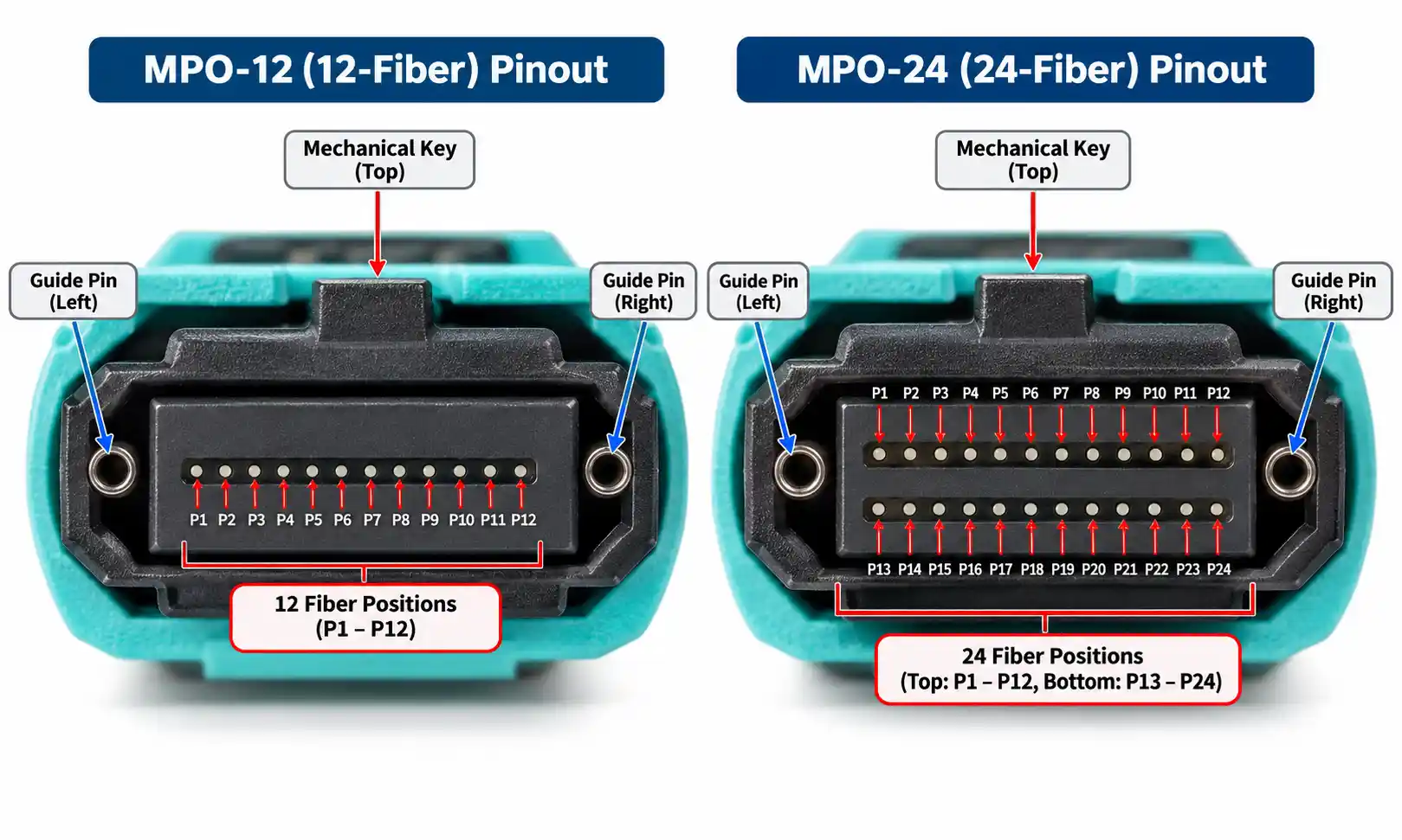
Data-center links often combine tight loss budgets with many connector points, so both total loss and event-level quality matter. A link can pass total loss yet still contain a high-reflectance connector that hurts performance in some high-speed single-mode applications. In MPO-based environments, technicians frequently pair fast pass/fail acceptance with an MPO optical power meter for loss and an OTDR for reflectance, event mapping, and troubleshooting.
FTTH and Access Networks
In FTTH and access networks the OTDR is especially useful, because routes can be long, branched, outdoor, and spliced, and locating a fault distance saves hours of field work. Power-meter testing still matters for checking received optical power at ONTs, splitters, and customer endpoints. When a subscriber connection fails, an OTDR helps locate the break, while structured PON fault scenarios and troubleshooting guidance helps interpret what the trace is showing on a split network.
Long-Distance Backbone Fiber
For long-haul fiber, the OTDR shows fiber length, splice points, attenuation slope, and unexpected events over distance, and it is ideal for building a baseline trace before the link enters service. A light source and power meter is still needed wherever the project requires direct end-to-end loss verification, so commissioning records for a backbone typically keep both the loss report and the OTDR baseline.
Can an OTDR Replace a Light Source and Power Meter?
In most professional workflows, no. The two tools answer different questions. The LSPM/OLTS answers whether the whole link meets the allowed loss budget; the OTDR answers where the events, losses, and reflections are located.
This distinction is important for certification. Industry testing guidance treats end-to-end loss measurement as the Tier 1 acceptance test and OTDR characterisation as Tier 2 (extended) testing. The Fiber Optic Association is explicit in its installation and testing guidance that OTDRs are used to verify installation quality or to troubleshoot, but OTDR testing should not be used on its own to determine cable-plant loss for acceptance. TIA and IEC standards take a similar position, which is why an OTDR-only submission may not be accepted unless the project specification clearly allows it.
What to Include in a Fiber Test Report
- Link identification, end points, and fiber type (single-mode or multimode, and grade).
- OLTS or LSPM loss result per wavelength, with the project loss-budget limit and pass/fail.
- Length and polarity results.
- OTDR trace and event table where Tier 2 testing applies, with per-event loss and reflectance.
- Reference method used and the test standard followed.
- Connector inspection records and any defects found.
- Tester model, calibration date, and launch/receive cord details.
- Date, technician, and any notes on conditions or exceptions.
Common Mistakes to Avoid
Using an OTDR Alone for Certification
An OTDR is powerful, but it is not always accepted as a standalone certification tool. Check the project specification before submitting OTDR-only reports.
Ignoring Launch and Receive Cables
Without a proper launch cable, the OTDR cannot characterise the first connector; without a receive cable, it cannot properly evaluate the far-end connector.
Testing Dirty Connectors
Dirty end faces create high loss and reflectance and can spread contamination. Always inspect and clean before testing.
Testing at the Wrong Wavelength
Test at the wavelength the application or specification requires. Multimode and single-mode links use different wavelengths and setups, and multimode loss testing should use encircled-flux-compliant sources for consistent results.
Looking Only at Total Loss
A link can pass total loss yet still hide a poor connector, an unexpected event, or a high-reflectance point. For critical links, an OTDR adds the visibility a loss test cannot.
How We Approached This Comparison
The split between end-to-end loss testing (Tier 1) and OTDR characterisation (Tier 2) follows ANSI/TIA-568.3-D and ISO/IEC 14763-3, with measurement procedures drawn from the TIA-526 / OFSTP-7 and OFSTP-14 methods, connector inspection from IEC 61300-3-35, and encircled-flux launch conditions from IEC 61280-4-1. Where a project specification differs from general guidance, the specification and the applicable standard always take precedence, and an OTDR-only result should not be assumed acceptable for certification unless the specification allows it.
FAQ
Q: Is an OTDR better than a light source and power meter?
A: Neither is universally better. An OTDR is better for locating faults and events; a light source and power meter is better for measuring total end-to-end insertion loss. The right tool depends on the testing goal.
Q: Do I need both an OTDR and an LSPM?
A: For simple loss checks, an LSPM or OLTS may be enough. For troubleshooting, long routes, high-speed links, backbone fiber, customer acceptance, or detailed documentation, using both is usually the stronger approach.
Q: What is the difference between LSPM and OLTS?
A: An LSPM is generally a separate source and power meter read manually. An OLTS is a more automated, often two-ended test set that adds pass/fail limits, dual-wavelength and bidirectional testing, length and polarity checks, and reporting. Both measure total insertion loss.
Q: Can a power meter find a fiber break?
A: A power meter can show that little or no light reaches the far end, but it cannot tell you where the break is. An OTDR can estimate the distance to the break.
Q: Can an OTDR measure insertion loss?
A: An OTDR can estimate event loss and link loss, but it calculates those values from reflected and backscattered light. A light source and power meter measures end-to-end optical loss directly, which is why loss testing is the accepted acceptance method.
Q: What is the difference between Tier 1 and Tier 2 fiber testing?
A: Tier 1 (basic) testing measures end-to-end insertion loss, length, and polarity with an OLTS or LSPM. Tier 2 (extended) testing adds OTDR characterisation of individual events such as splices and connectors. Tier 2 supplements Tier 1; it does not replace it.
Q: Why does my OTDR need a launch cable?
A: The launch cable moves the OTDR's dead zone off the first connector so the instrument can measure that connector accurately. A receive cable does the same for the far-end connector.
Q: Should I test an OTDR in both directions?
A: For accurate per-event loss, yes. A splice can read differently from each direction, so bidirectional traces are averaged to remove that directional effect.
Q: Which tool is better for FTTH testing?
A: For service activation, a power meter checks optical power levels at the ONT or splitter. For locating cable faults, splice issues, or route problems, an OTDR is more useful.
Q: Which tool is better for data center fiber testing?
A: For data-center acceptance, an OLTS is usually preferred for fast insertion-loss testing. An OTDR is useful for finding reflective events, bad connectors, hidden patch points, and other event-level problems.
Q: What wavelengths should I test at?
A: Multimode links are typically tested at 850 nm and optionally 1300 nm; single-mode links at 1310 nm and commonly 1550 nm. Always follow the wavelengths the application or specification requires.
Q: Is an OTDR-only report enough for certification?
A: Usually not. Most standards and specifications treat the OLTS/LSPM loss result as the acceptance test and the OTDR trace as supporting documentation. Confirm the project specification before relying on an OTDR-only report.
Conclusion
The choice between OTDR vs light source and power meter is not about which tool is better - it is about which question you need to answer. A light source and power meter tells you how much optical power the full link loses. An OTDR tells you where the loss, reflection, bend, splice, or fault events are located.
For basic loss verification, use a light source and power meter or OLTS. For troubleshooting and event mapping, use an OTDR. For critical links, high-speed networks, long-distance routes, and formal handover documentation, use both - direct end-to-end loss measurement for acceptance, and OTDR visibility for everything you need to locate and maintain.