When an MTP/MPO link stays dark during turn-up, the first suspect is not always the cable itself. The trunk may be clean, the transceiver may be correct, and the cassette may still be usable. In many cases, the problem is that the installed polarity path does not match the channel design.
This is where MTP PRO polarity change can help. It gives trained installers a controlled way to correct certain connector-level polarity mismatches in the field, as long as the installed assembly supports the change and the project specification allows it. It should not be treated as a shortcut around polarity planning. It is a field correction option for a verified mismatch after the link has already been routed, dressed, connected, and tested.

Quick Answer: What Is MTP PRO Polarity Change?
MTP PRO polarity change is a connector-level field configuration feature. It changes the connector keying orientation used for polarity control; it does not rebuild the cable, resplice fibers, change the cassette's internal mapping, or redesign the full channel.
US Conec describes MTP PRO connectors as supporting field polarity change and field pin change while maintaining connector integrity. Its official product information also describes the polarity change as a color-coded operation that does not require removing the connector housing. The related MTP PRO polarity and pin removal field tool is intended for this type of controlled field operation.
For an installed MTP/MPO cable assembly, the practical value is simple: if the cable is already in place and the mismatch is proven to be at the connector configuration level, MTP PRO polarity change may prevent unnecessary replacement work.

Why Polarity Errors Are Harder to Fix After Installation
Polarity mistakes are much easier to prevent during design than to correct after installation. Once a pre-terminated MTP/MPO trunk cabling assembly has been pulled through overhead trays, dressed into cabinets, and connected to patch panels or cassettes, replacing it can disturb more than one link.
In a high-density MTP/MPO environment, polarity is not decided by one connector alone. The final Tx-to-Rx path may involve the trunk cable, adapter orientation, connector gender, cassette mapping, harness or fanout mapping, transceiver lane assignment, and the patching method. If one part of that path follows a different assumption from the rest of the channel, several lanes can fail at once.
The TIA FOTC summary of ANSI/TIA-568.3-E notes that different array polarity methods may not be interoperable and recommends selecting one method in advance and maintaining it consistently throughout the installation. MTP PRO polarity change does not replace that planning. It helps only when the installed assembly and the documented channel plan can still be brought into alignment through a controlled connector-level change.

What MTP PRO Polarity Change Can and Cannot Change
MTP PRO polarity change can adjust a compatible connector's polarity configuration. It cannot fix every MTP/MPO link fault. Before touching the connector configuration, the installer should understand which part of the channel is actually wrong.

| It can help when | It cannot fix when |
|---|---|
| The installed connector configuration does not match the verified channel plan. | The entire polarity design is wrong, undocumented, or based on mixed methods. |
| The installed cable uses compatible MTP PRO connectors and supports field polarity change. | The cable is not MTP PRO or the project specification does not allow field modification. |
| The mismatch is confirmed by polarity testing or port-map verification. | The real problem is contamination, high insertion loss, damaged fiber, wrong fiber type, or wrong transceiver type. |
| The correction is limited to the connector-level polarity configuration. | The cassette, trunk, adapter, and transceiver lane assignment follow different design assumptions. |
| The change can be tested, labeled, and documented after correction. | The final configuration cannot be recorded in the as-built documentation. |
MTP PRO Polarity Change vs Pin Change
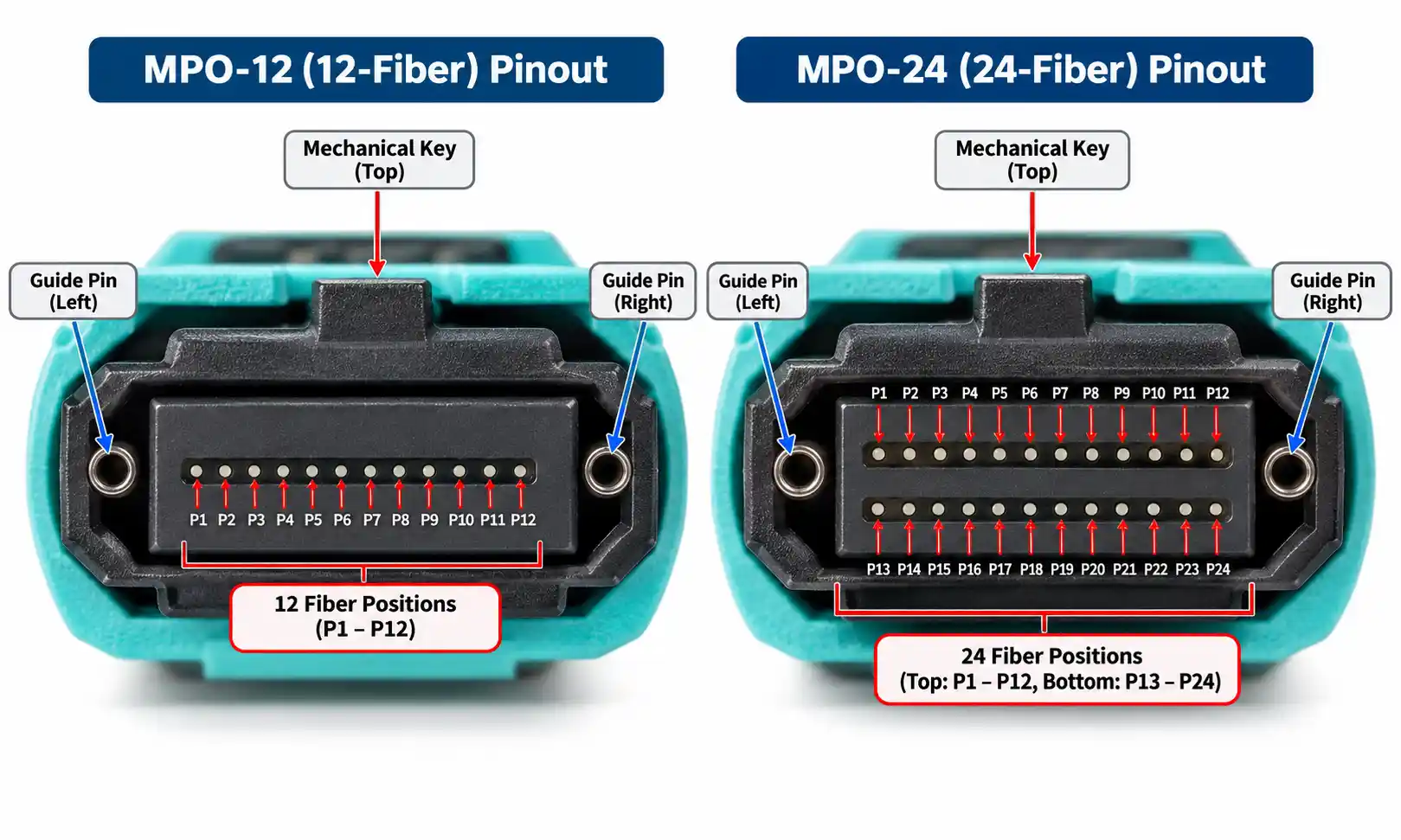
Polarity change and pin change should not be treated as the same correction. In MTP/MPO systems, polarity is about maintaining the intended Tx-to-Rx signal path. Pin configuration is about whether the connector is pinned or unpinned so that two MTP/MPO connectors can mate correctly.
A polarity change may be relevant when the lane path is reversed or does not match the documented polarity method. A pin change may be relevant when the connector gender does not match the mating interface. If a pinned connector is mated to another pinned connector, the connectors may not mate correctly. If an unpinned connector is mated to another unpinned connector, alignment can be unreliable or impossible.
For this reason, connector gender should be checked together with polarity. If the site uses mixed trunks, cassettes, patch cords, and equipment ports, review the connector configuration before deciding whether the issue is polarity, gender, mapping, or another fault. Related component choices can also be checked under fiber optic connectors.
How to Confirm an MTP/MPO Polarity Mismatch
A dark link does not automatically prove a polarity problem. According to Fluke Networks fiber cleaning and inspection guidance, contaminated connections remain a leading cause of fiber-related problems and test failures. Cleaning and inspection should come before any polarity modification.
Use this workflow before changing connector polarity:

- Check the design record. Confirm the intended polarity method, fiber count, connector gender, cassette mapping, adapter orientation, and port map.
- Inspect and clean connector end faces. Do this before remating the connectors. A dirty MPO end face can create loss or reflection problems that look like a link failure.
- Confirm adapter and port orientation. Adapter orientation can affect key alignment. Related components can be reviewed under fiber optic adapters.
- Verify connector gender. Pinned and unpinned connectors must be matched correctly.
- Check continuity and routing. A visual fault locator can help locate obvious breaks, incorrect routing, or continuity issues in some troubleshooting situations.
- Test loss and polarity. Use project-approved test equipment to separate insertion loss problems from polarity problems. General background on field testing can be found in fiber optic testing equipment and guidelines.
- Change polarity only after confirmation. If the loss result is within the project acceptance criteria but the polarity map fails against the documented port map, then a connector-level polarity correction may be appropriate.
Quick Diagnosis: Polarity Issue or Something Else?
| Symptom | Likely issue | What to check before changing polarity |
|---|---|---|
| Several lanes fail at the same time, but insertion loss is within the project loss budget. | Possible polarity mismatch or lane mapping mismatch. | Compare the polarity test result with the port map and cassette mapping. |
| Loss is high or unstable after mating. | Contamination, damaged end face, poor mating, or cable damage. | Inspect, clean, remate, and retest insertion loss. |
| The connectors do not mate correctly. | Possible gender mismatch. | Check pinned and unpinned connector pairing before changing polarity. |
| Only one side of the channel is changed or replaced. | Mixed design assumptions between old and new components. | Check trunk type, cassette mapping, adapter orientation, and transceiver interface. |
| A breakout application works on one end but not the other. | Harness, fanout, or cassette mapping may not match the intended path. | Verify whether the channel uses harness cables, fanout cables, or module breakout. |
Where MTP PRO Polarity Change Is Most Useful
1. A Routed Trunk Has a Confirmed Connector-Level Mismatch
The clearest use case is an installed trunk that is difficult to replace but still compatible with field polarity change. For example, a pre-terminated trunk has already been routed through trays, dressed into cabinets, and connected to panels. Reordering the cable would delay the project, but testing shows that the connector configuration does not match the documented channel plan.

2. Cassette and Trunk Mapping Do Not Align
A trunk may be technically usable but mapped differently from the cassette layout expected in the project. If the link connects to an MPO/MTP LGX module cassette and the lane path does not line up, first verify the cassette mapping and port map. MTP PRO polarity change may help only if the mismatch is truly at the compatible connector level.
3. Breakout Links Need a Verified Correction Path
In breakout applications, the installer should confirm whether the link uses MPO/MTP harness cables, MPO/MTP fanout cables, or a cassette-based breakout. These assemblies may map fibers differently depending on whether the channel is designed for direct array-to-array transmission, equipment-side patching, or module breakout.
4. High-Speed Turn-Up Is Delayed by a Verified Polarity Problem
Polarity errors are especially disruptive in parallel optics. A 40G or 100G SR4 channel uses multiple lanes, so one polarity or mapping error can affect more than a single duplex pair. The TIA FOTC 100GBASE-SR4 application overview describes 100GBASE-SR4 as using short-wavelength parallel transmission over four lanes of multimode optical fiber cabling. When deploying 40G QSFP transceivers or 100G QSFP28 transceivers with MTP/MPO interfaces, polarity verification should be part of turn-up, not an afterthought.
MTP PRO Polarity Change Decision Checklist
Before approving a field polarity change, confirm all of the following:
- The installed cable assembly uses compatible MTP PRO connectors.
- The project specification allows field polarity configuration.
- The intended polarity method and port map are documented.
- The connector end faces have been inspected and cleaned.
- Insertion loss is within the project acceptance criteria or has been separately explained.
- The polarity test or port-map verification confirms a connector-level mismatch.
- The correction does not conflict with cassette mapping, adapter orientation, or transceiver lane assignment.
- The correct MTP PRO field tool is available.
- The technician is trained to follow the connector supplier's instructions.
- The final configuration can be labeled, tested, and recorded.
If any of these items cannot be confirmed, do not treat polarity change as the default fix. Investigate the channel design, cable condition, component compatibility, and project requirements first.
Example: Fixing an MTP/MPO Polarity Mismatch During 100G Turn-Up

Consider a data center team adding a 12-fiber MTP trunk between two high-density patch panels. The trunk has already been routed through overhead trays and dressed into cabinets. Each end connects to an LGX cassette, and the planned application is 100G SR4.
During turn-up, four lanes do not come up. The team does not immediately change polarity. First, they inspect and clean the connector end faces. Then they verify that the transceivers match the planned application, confirm that the trunk is connected to the correct cassette ports, and run insertion loss testing. The loss result is within the project loss budget, but the polarity test shows that the Tx lanes are not reaching the expected Rx lanes according to the documented port map.
| Step | Finding | Decision |
|---|---|---|
| End-face inspection | No visible contamination after cleaning and inspection. | Continue troubleshooting. |
| Transceiver check | The modules match the intended 100G SR4 application. | Do not replace the transceivers. |
| Insertion loss test | Loss is within the project acceptance criteria. | High loss is not the primary fault. |
| Polarity test | The lane map does not match the documented channel plan. | Connector-level polarity correction may be allowed. |
| Field correction | The installed trunk uses compatible MTP PRO connectors. | Use the proper field tool, then retest and document the result. |
In this situation, replacing the trunk would require reopening the route and disturbing nearby cabling. A conversion jumper might bring the link up, but it would add another mapping point that must be maintained in future records. If the project permits field configuration, MTP PRO polarity change can be the cleaner correction because the final state can be retested, labeled, and documented.
MTP PRO Polarity Change vs Other Correction Methods
| Correction method | Best used when | Main risk |
|---|---|---|
| Reorder the cable | The installed cable does not match the design, or field modification is not allowed. | Longer lead time, higher cost, and possible project delay. |
| Use a conversion jumper | A fast temporary fix or approved permanent conversion is needed. | Extra channel component, additional insertion point, and future documentation confusion. |
| Manual connector rework | A qualified specialist performs controlled rework under approved conditions. | Fiber exposure, mechanical damage, or connector performance risk if done incorrectly. |
| Use MTP PRO polarity change | The assembly supports field polarity change and the mismatch is confirmed. | Wrong correction if testing, documentation, or design verification is incomplete. |
What to Document After the Field Change

Every MTP PRO polarity change should leave a clear record. Without documentation, the next technician may treat the changed connector as a factory-default assembly and undo the correction by accident.
Record the following items after the field change:
- Cable ID or trunk ID
- Cabinet, panel, and port numbers at both ends
- Original connector configuration
- Final connector configuration
- Reason for the change
- Tool used for the field operation
- Technician name or team record
- Date of change
- Pre-change polarity test result
- Post-change polarity test result
- Post-change insertion loss result
- Updated label reference
- Updated port map or as-built drawing reference
If the site requires formal certification, use approved testing equipment or an MPO/MTP polarity testing machine to verify the corrected link before it is released for service. Related tools may also be reviewed under fiber tool kits.
When MTP PRO Polarity Change Is Not the Right Fix
MTP PRO polarity change should not be used as a general workaround for every MTP/MPO link problem. It is not the right fix when:
- The design team has not confirmed the intended polarity method.
- The trunk, cassette, adapter, and transceiver lane assignment are based on different design assumptions.
- The installed cable assembly does not support MTP PRO field polarity change.
- The connector is damaged, contaminated, or outside acceptable optical performance.
- The issue is high insertion loss rather than polarity.
- The project specification requires factory-fixed assemblies only.
- The final configuration cannot be labeled, tested, and documented.
In these cases, replacing the assembly, correcting the channel design, or using an approved conversion component may be safer than changing polarity in the field.
Best Practices After MTP PRO Polarity Change
- Retest immediately. Confirm both polarity and insertion loss after the adjustment.
- Inspect the connector again. Handling during troubleshooting can introduce new contamination.
- Update labels. Mark the changed connector or port clearly enough for future maintenance.
- Revise the port map. Make sure the final lane path is reflected in the project documentation.
- Save test records. Keep polarity and loss results with the project file.
- Standardize future additions. New trunks, cassettes, harnesses, fanouts, and patch cords should follow the same verified polarity plan.
FAQ: MTP PRO Polarity Change
Q: What is the best cable for solar panels?
A: For the DC side of a PV system, use a PV-rated solar DC cable or PV wire that meets the required voltage, temperature, UV resistance and certification for the project market.
Q: What size solar cable should I use?
A: Cable size depends on current, voltage drop, route length, conductor material, ambient temperature, grouping and installation method. Do not choose cable size only by habit.
Q: Is H1Z2Z2-K better than PV1-F?
A: H1Z2Z2-K is commonly used in modern European and IEC-based PV projects, while PV1-F may still appear in older or project-specific specifications. The better choice depends on the project standard and local acceptance.
Q: What is the difference between PV wire and solar cable?
A: The terms are sometimes used loosely, but in procurement they should be tied to standards and market requirements. UL PV Wire is common in North American projects, while H1Z2Z2-K solar cable is common in IEC or European specifications.
Q: Can I use normal electrical wire for solar panels?
A: For exposed outdoor PV DC circuits, normal electrical wire is usually not a suitable replacement unless the project design and local code clearly allow it. PV cables are designed for sunlight, weather and PV operating conditions.
Q: Why are solar cables often red and black?
A: Red and black help identify DC polarity. Red is commonly used for positive and black for negative, but installers should always follow project drawings, labels and local practice.
Q: Are solar connectors as important as the cable?
A: Yes. A poor connector or poor crimp can create heat, water ingress or failure. Always check connector compatibility, ratings and installation instructions.
Q: Can solar cables be buried underground?
A: Only use a cable underground if its construction, sheath, protection method and project standard allow it. Some cables require conduit or additional mechanical protection.
Q: Do solar projects need communication cables?
A: Many PV projects need communication cables for inverter monitoring, data loggers, weather stations, trackers, alarms and SCADA systems. Larger projects may require more robust data cabling than small rooftop systems.
Q: How can I reduce voltage drop in a solar cable run?
A: You can reduce voltage drop by shortening the cable route, increasing conductor size, reducing current per cable where the design allows, or adjusting the system design under engineering guidance.
Conclusion
MTP PRO polarity change can reduce avoidable MTP/MPO cabling rework when an installed, compatible assembly has a confirmed connector-level polarity mismatch. Its value is strongest when the cable is already routed, the mismatch is verified, and replacing the trunk would delay the project or disturb nearby links.
The safest workflow is to confirm the channel plan, inspect and clean the connectors, test loss and polarity, verify that the issue is truly polarity-related, use the proper MTP PRO field tool, retest after the change, and update all records. Used this way, MTP PRO polarity change is not a shortcut around good cabling design. It is a practical field correction method that helps high-density fiber systems remain easier to install, verify, and maintain.