Choosing the right solar cables is one of the most important steps in a safe and efficient PV project. Solar panels and inverters often get most of the attention, but cables connect every part of the system: modules, strings, combiner boxes, inverters, transformers, grounding networks and monitoring equipment.

The quick answer is this: choose solar cables by application first, then confirm the cable size, voltage rating, installation environment, certification and supplier documents. A cable that is suitable for a short rooftop string may not be suitable for a long ground-mounted route. A cable accepted in one market may not pass inspection in another.
Practical rule: start with the system layout and cable schedule, not only with cable price. A good solar cable selection process should connect engineering requirements with real procurement details.
Quick Answer: What Cables Do You Need for a Solar Project?
Most solar projects use several cable types, not just one. The exact list depends on the system size, voltage, layout and local requirements, but the main cable groups are usually the same.
| Cable Type | Typical Application | Key Selection Points |
|---|---|---|
| Solar DC cable / PV wire | Module interconnection, string wiring, string to combiner box, combiner box to inverter | Voltage rating, UV resistance, weather resistance, ampacity, temperature rating, connector compatibility |
| Solar AC cable | Inverter output to distribution board, transformer or grid connection point | AC voltage, load current, short-circuit condition, flame rating, installation method |
| Grounding cable | Module frames, mounting structures, inverter grounding, equipment bonding | Low-resistance path, corrosion resistance, bonding method, local code |
| Communication / control cable | Inverter monitoring, data logger, SCADA, tracker control, weather station | Signal distance, shielding, outdoor protection, interference resistance |
| Overhead or MV cable | Grid connection, longer-distance power transmission, large PV plants | Voltage level, mechanical strength, route length, grid requirement |
| Solar connectors and extension leads | Module connection, string extension, inverter input connection | Connector compatibility, crimping quality, waterproof rating, cable diameter range |
For the power side of the system, solar DC and AC cables carry electrical energy. For the monitoring side, communication cables carry data. In commercial and utility-scale projects, both sides should be planned together because poor communication cabling can make troubleshooting, inverter monitoring and plant maintenance much harder.

Why Solar Cable Selection Matters
Solar cables operate in demanding conditions. Many DC cables are exposed to sunlight, heat, rain, humidity, dust, wind and mechanical stress for many years. If the cable is not designed for PV use, the system may face insulation aging, voltage drop, overheating, connector failure or inspection problems.
Cable selection also affects energy performance. A cable with excessive resistance wastes energy as heat. The loss may be small in a short residential route, but it can become more important in commercial rooftops or utility-scale plants with long cable runs.
The goal is not to choose the thickest cable automatically. The goal is to choose a cable that matches the circuit current, voltage, route length, installation method, environmental exposure and required standard.
Step 1: Map the Cable Segments in Your PV System
Before choosing a cable type or cable size, map every cable segment in the PV system. Each segment has a different function.

Module to Module and String Wiring
This section normally uses solar DC cable or PV wire with compatible PV connectors. The cable must be rated for outdoor use, direct sunlight, temperature variation and the system voltage.
This is also where connector quality matters. A good cable with a poor crimp or incompatible connector can still become a failure point.
String to Combiner Box
For systems with multiple strings, DC cables run from the string end to the combiner box. Cable length becomes important here because longer routes increase voltage drop.
A short rooftop route and a long ground-mounted string route should not be treated the same. Route length, current and installation temperature should be checked before finalizing the cable size.
Combiner Box to Inverter
This section may carry higher current than a single string. It is often the first point where engineering calculation becomes more important than choosing a common cable size by habit.
For this route, check ampacity, voltage drop, grouping, temperature derating and protective device coordination.
Inverter to AC Distribution Board or Transformer
After the inverter converts DC power into AC power, AC cable is used to transmit power to the distribution board, transformer or grid connection point. The AC side should be selected according to AC voltage, current, short-circuit requirements, installation method and local electrical code.
Grounding, Monitoring and Control Routes
Grounding conductors provide a low-resistance path for fault currents and help protect people and equipment. Communication and control cables do not transmit power, but they are important for monitoring, control, fault alarms and system maintenance.
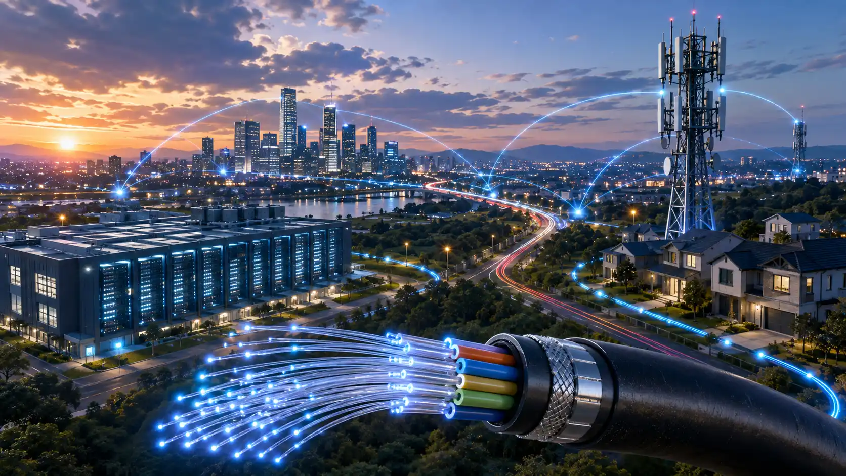
In larger PV projects, the communication network may connect inverters, data loggers, weather stations, trackers and SCADA systems. Poor communication cabling may not reduce actual power generation, but it can affect monitoring accuracy, troubleshooting speed and maintenance efficiency. For long-distance plant monitoring, fiber optical cable is often preferred because it supports longer transmission distance and stronger resistance to electromagnetic interference than copper data cable.
Step 2: Choose the Cable Type by Application
A practical way to avoid mistakes is to choose cables by application rather than by appearance.

| Application | Recommended Cable Type | What to Check |
|---|---|---|
| Panel interconnection | Solar DC cable / PV wire | UV resistance, voltage rating, temperature rating, connector compatibility |
| String to combiner box | Solar DC cable | Current, route length, voltage drop, outdoor rating |
| Combiner box to inverter | Larger DC cable if required | Ampacity, voltage drop, grouping, installation method |
| Inverter AC output | Solar AC cable or suitable LV power cable | AC voltage, current, insulation, flame rating, local standard |
| Transformer or substation connection | LV or MV cable | Voltage level, short-circuit capacity, burial or tray installation |
| Module frame grounding | Grounding cable | Bonding method, corrosion resistance, local code |
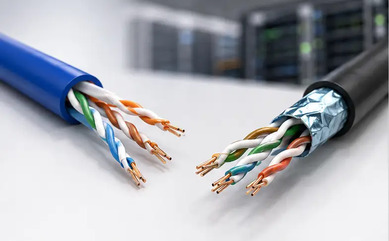
| Monitoring and communication | Communication/control cable, Ethernet cable or fiber cable | Distance, signal stability, shielding, routing separation |
| Long-distance overhead line | AAC, AAAC, ACSR or project-specified conductor | Span, mechanical strength, weather condition, grid requirement |
| Long-distance overhead line | AAC, AAAC, ACSR or project-specified conductor | Span, mechanical strength, weather condition, grid requirement |
For exposed outdoor PV DC circuits, do not replace PV cable with ordinary building wire unless the project design and local code clearly allow it. PV cables are designed for solar environments, while ordinary wires may not have the same UV, moisture, temperature or mechanical performance.
For outdoor data links, pre-terminated outdoor cable assemblies can reduce field termination work and improve installation consistency. For shorter indoor or cabinet-level connections, a suitable network cable may be enough if the distance and electromagnetic environment allow it.
Step 3: Size Solar Cables Correctly
Cable size should not be selected only by habit. A 4mm² cable may be suitable in one string circuit but unsuitable in another. A 6mm² cable may reduce voltage drop on a long route, but it may be unnecessary for a short route.
The right size depends on current, cable length, voltage drop, conductor material, temperature and installation method.
Start With Circuit Current
For a DC string, check the module current and the number of strings connected in parallel. For an inverter AC output, check the maximum AC output current of the inverter.
Do not size the cable from the inverter model name alone. Use the electrical values in the project design or manufacturer datasheet.
Check Voltage Drop
Voltage drop is one of the most common reasons for upsizing solar cables. The longer the cable run and the higher the current, the greater the voltage drop.
Longer cable route + higher current + smaller conductor = higher voltage drop.
A cable may be safe from an ampacity perspective but still be too small if the voltage drop is too high. Many project specifications define an acceptable voltage drop target, so the buyer should not assume one fixed value for every project.

Measure the Real Route Length
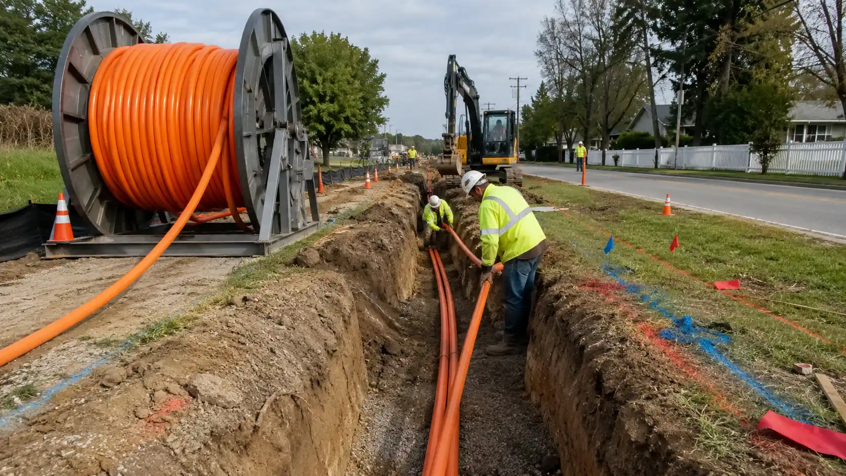
Use the actual cable path, not only the straight-line distance on the layout drawing. Rooftop cable routes may go around walkways, parapets, cable trays and inverter locations. Ground-mounted projects may have long string routes from module rows to combiner boxes or inverter stations.
For long routes, voltage drop often becomes the main sizing driver.
Apply Temperature and Grouping Factors
Solar cables often operate in hot environments. Rooftop cables may be exposed to high surface temperature, and cables grouped in conduit or tray may have reduced heat dissipation.
If the cable is installed in conduit, bundled with other cables, exposed to high ambient temperature or routed near heat sources, derating should be checked before finalizing the size.

Consider Copper vs Aluminum
Copper is common for PV DC circuits because it has good conductivity and flexibility. Aluminum may be used in larger AC or utility-scale routes to reduce cost and weight, but it usually requires a larger cross-sectional area and compatible terminals.
Do not substitute aluminum for copper only to reduce price. Confirm conductor compatibility, terminal type, installation practice and local approval.
Practical Sizing Example
Suppose two string routes carry the same current. Route A is short and close to the inverter. Route B is longer and runs across a hot rooftop before reaching the combiner box.
Even if both routes carry the same current, Route B may need a larger cable size because voltage drop and thermal conditions are less favorable. This is why a purchasing list should not specify only "PV cable 4mm²" or "PV cable 6mm²" without route length and installation details.
Step 4: Check Solar Cable Standards and Certifications
Solar cable standards vary by market. A cable accepted in one country may not be accepted in another. Always confirm the project country, project specification, utility requirement and authority having jurisdiction before ordering.

| Market / Project Type | Common Standard or Requirement | Buyer Should Verify |
|---|---|---|
| European and IEC-based projects | IEC 62930, EN 50618, H1Z2Z2-K where required | Certificate validity, cable marking, voltage rating, temperature rating |
| North American projects | UL 4703 PV Wire, NEC/NFPA 70 project requirements | UL listing, conductor type, wet/dry temperature rating, voltage rating |
| PV connector systems | UL 6703 or IEC connector-related requirements where specified | Connector rating, cable diameter compatibility, crimping method |
| Export projects | Local project approval and utility requirements | Certificate copy, test report, sample approval, cable marking |
Buyer note: do not rely only on the product name printed in a quotation. Ask for the certificate, datasheet, cable marking, test report and project approval documents before placing an order.
Step 5: Compare H1Z2Z2-K, PV1-F and UL PV Wire
H1Z2Z2-K, PV1-F and UL PV Wire are often mentioned in solar cable purchasing, but they are not interchangeable in every project.

| Cable Name | Typical Context | What Buyers Should Check |
|---|---|---|
| H1Z2Z2-K | Common in European and IEC-based PV projects | EN 50618 or IEC 62930 certificate, voltage rating, temperature rating, cable marking |
| PV1-F | Still requested in some older or project-specific specifications | Whether the project still accepts PV1-F or requires H1Z2Z2-K |
| UL PV Wire | Common in North American PV projects | UL listing, NEC acceptance, conductor material, voltage rating |
Step 6: Plan Cable Routing and Protection
Good cable selection can still fail if cable routing is poor. Cable routing should protect the cable from sharp edges, standing water, abrasion, excessive bending, mechanical impact and long-term UV exposure.
- Keep string cables neat, supported and easy to inspect.
- Avoid leaving connectors under tension.
- Use conduit, tray or protective sleeves where physical damage is possible.
- Maintain the cable manufacturer's minimum bend radius.
- Separate power cables from communication cables where interference is a concern.
- Label strings, combiner inputs, inverter outputs and monitoring lines clearly.
- Document the cable route for inspection and maintenance.
For commercial and utility-scale projects, cable routing should be documented in drawings so that installation, inspection and maintenance teams follow the same plan. For monitoring or data transmission in exposed outdoor areas, indoor/outdoor fiber cables or rugged outdoor fiber assemblies may be more suitable than ordinary indoor patch cables. For harsh field environments, FTTA outdoor solutions can provide useful references for waterproof, outdoor-rated fiber connection design.

Step 7: Do Not Ignore Connectors and Pre-Assembled Leads
A PV cable is only as reliable as its termination. Many solar cable failures happen at the connector or crimping point, not in the middle of the cable.
When choosing solar connectors or pre-assembled extension leads, check:
- Rated voltage and current
- Connector compatibility
- Cable outer diameter range
- Waterproof and dustproof performance
- Crimping method and tool requirement
- Polarity identification
- Manufacturer installation instructions
- Whether different connector brands are allowed to mate in the project
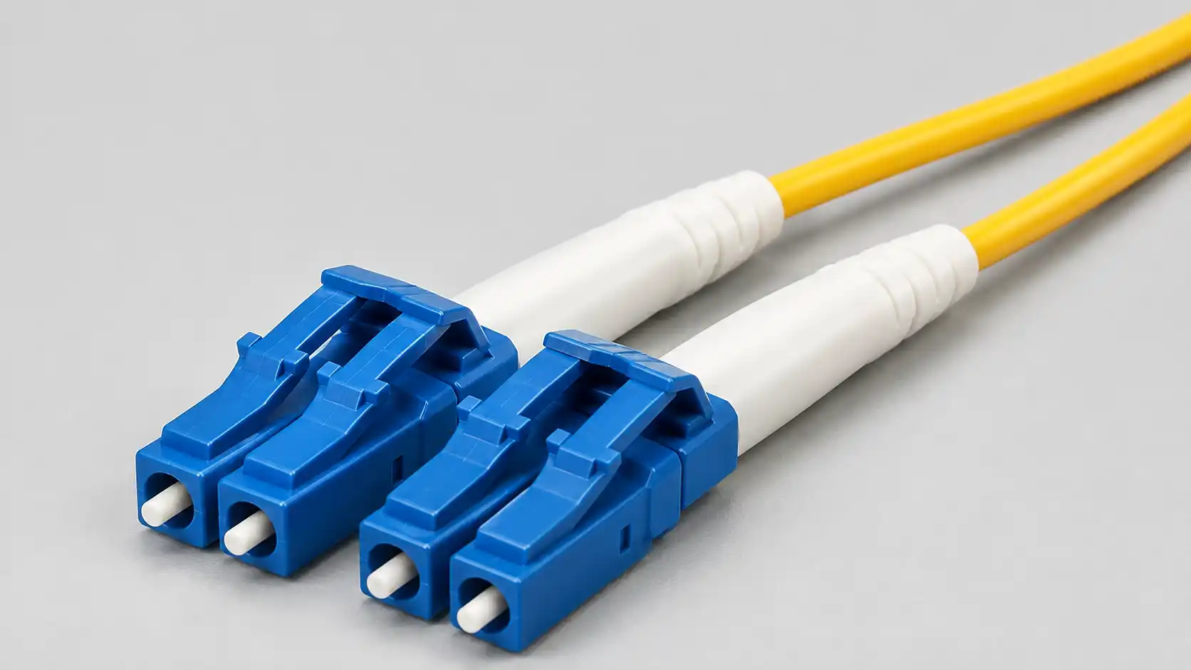
UL notes that solar component certification can include PV connectors and related products, including solar materials and components certification. For fiber-based monitoring networks, the choice of fiber optic connectors, fiber optic adapters and fiber termination boxes can affect installation speed, serviceability and long-term reliability.
Factory-assembled solar extension cables can reduce field labor and improve consistency, but they should still be ordered according to exact cable length, connector type, polarity, cable size and project standard.

Step 8: Select Communication and Control Cables for Monitoring
Communication cables do not directly transmit solar power, but they are important for system monitoring and maintenance. They may carry inverter data, power output information, fault alarms, tracker signals, weather station data or SCADA communication.
For small rooftop systems, communication cabling may be simple. For larger commercial or utility-scale projects, the communication network should be planned with the same care as the power cabling.
Check:
- Transmission distance
- Indoor or outdoor installation
- EMI environment
- Shielding requirement
- Copper or fiber selection
- Connector type
- Spare capacity for future expansion
- Protection against water and mechanical damage
If the communication cable fails, the solar plant may still generate power, but operators may lose visibility of system status, alarms and performance data. For long-distance plant monitoring, OS2 singlemode patch cords and compatible fiber optic transceivers are common choices when the network design requires singlemode fiber links. For exposed outdoor interfaces, waterproof fiber optic connectors may be considered where the project environment requires sealed connections.
Buyer Checklist: What to Confirm Before Ordering Solar Cables
Before requesting a quote, prepare enough project information. A vague inquiry such as "quote 6mm² solar cable" may lead to the wrong cable, wrong certificate or wrong packaging.
| Information to Provide | Why It Matters |
|---|---|
| Project country or target market | Determines certification and approval requirements |
| Cable application | DC string, AC output, grounding, communication or overhead route |
| System voltage | Confirms voltage rating |
| Current value | Supports ampacity selection |
| One-way route length | Needed for voltage drop evaluation |
| Installation method | Open air, conduit, tray, direct burial or rooftop installation |
| Environmental condition | UV, humidity, salt spray, high temperature or mechanical stress |
| Required certificate | Prevents wrong-market purchasing |
| Connector type | Affects cable diameter compatibility and installation quality |
| Packing length and reel type | Helps installation planning and logistics |
| Test report or quality documents | Supports project inspection and approval |
Common Mistakes When Choosing Solar Cables
| Mistake | Why It Is a Problem | Better Practice |
|---|---|---|
| Choosing only by price | Low-quality or wrong-standard cable may fail inspection or age quickly | Compare certificate, material, rating and documents |
| Using one size for all routes | Long routes may have excessive voltage drop | Check current, length and voltage drop by circuit |
| Replacing PV cable with ordinary wire outdoors | Ordinary wire may lack UV and weather resistance | Use PV-rated cable where required |
| Ignoring temperature derating | Cable may overheat in real conditions | Check ambient temperature, rooftop exposure and grouping |
| Mixing incompatible connectors | May cause overheating, water ingress or inspection issues | Confirm connector compatibility and crimping method |
| Poor cable labeling | Maintenance and troubleshooting become difficult | Label strings, AC circuits, grounding points and communication links |
| Buying without checking local standards | Cable may not pass inspection | Confirm standards before ordering |
| Forgetting communication cables | Monitoring and fault diagnosis may be unreliable | Plan data cabling together with power cabling |
Example Solar Cable Selection Scenarios
Residential Rooftop PV System
A residential rooftop system usually needs PV DC cable for panel connections, solar extension leads if the inverter is not close to the array, AC cable from the inverter to the distribution board and grounding cable for module frames and equipment.
The main concerns are UV exposure, rooftop temperature, connector quality, neat routing and local electrical inspection.
Commercial Rooftop PV System
A commercial rooftop project may have more strings, longer routes, higher current and a more complex monitoring network. Voltage drop, cable trays, conduits, labeling, fire-rated routing and inverter communication should be reviewed before procurement.
For this type of project, buyers should confirm both power cable specifications and communication cable requirements.
Utility-Scale Ground-Mounted PV Plant
A utility-scale plant may require DC string cables, combiner-to-inverter cables, LV or MV AC cables, grounding conductors, communication cables, weather station wiring and sometimes overhead conductors.
Cable selection should be engineering-led. Procurement should be based on drawings, cable schedules, certificates, test reports, installation conditions and project-specific approval requirements.
FAQ
Q: What is the best cable for solar panels?
A: For the DC side of a PV system, use a PV-rated solar DC cable or PV wire that meets the required voltage, temperature, UV resistance and certification for the project market.
Q: What size solar cable should I use?
A: Cable size depends on current, voltage drop, route length, conductor material, ambient temperature, grouping and installation method. Do not choose cable size only by habit.
Q: Is H1Z2Z2-K better than PV1-F?
A: H1Z2Z2-K is commonly used in modern European and IEC-based PV projects, while PV1-F may still appear in older or project-specific specifications. The better choice depends on the project standard and local acceptance.
Q: What is the difference between PV wire and solar cable?
A: The terms are sometimes used loosely, but in procurement they should be tied to standards and market requirements. UL PV Wire is common in North American projects, while H1Z2Z2-K solar cable is common in IEC or European specifications.
Q: Can I use normal electrical wire for solar panels?
A: For exposed outdoor PV DC circuits, normal electrical wire is usually not a suitable replacement unless the project design and local code clearly allow it. PV cables are designed for sunlight, weather and PV operating conditions.
Q: Why are solar cables often red and black?
A: Red and black help identify DC polarity. Red is commonly used for positive and black for negative, but installers should always follow project drawings, labels and local practice.
Q: Are solar connectors as important as the cable?
A: Yes. A poor connector or poor crimp can create heat, water ingress or failure. Always check connector compatibility, ratings and installation instructions.
Q: Can solar cables be buried underground?
A: Only use a cable underground if its construction, sheath, protection method and project standard allow it. Some cables require conduit or additional mechanical protection.
Q: Do solar projects need communication cables?
A: Many PV projects need communication cables for inverter monitoring, data loggers, weather stations, trackers, alarms and SCADA systems. Larger projects may require more robust data cabling than small rooftop systems.
Q: How can I reduce voltage drop in a solar cable run?
A: You can reduce voltage drop by shortening the cable route, increasing conductor size, reducing current per cable where the design allows, or adjusting the system design under engineering guidance.
Conclusion
Choosing solar cables for a PV project requires a full-system view. Start with the project layout, identify every cable segment, choose the cable type by application, size the cable by current and voltage drop, check temperature and installation conditions, verify the required standard and confirm supplier documents before ordering.
For small rooftop systems, connector quality, UV exposure and neat routing may be the main concerns. For commercial and utility-scale projects, voltage drop, cable management, grounding, documentation and communication cabling become more important.