
A CWDM SFP module is a fixed-wavelength optical transceiver used to send data over single-mode fiber as part of a Coarse Wavelength Division Multiplexing system. Its job is simple to state: let you carry several independent optical links over the fiber you already have, instead of pulling new cable.
For many enterprise, campus, metro, and data center interconnection projects, CWDM is attractive because it expands fiber capacity with passive optical parts rather than a complex active transport platform. But a single module is not a bandwidth booster on its own. A CWDM link only works when the wavelength, distance, optical budget, MUX/DEMUX channel plan, and switch compatibility are designed together. This guide walks through each of those decisions, including a full CWDM SFP wavelength chart and a worked optical-budget example.
Match the module wavelength to the MUX/DEMUX port exactly, prove the optical budget before you buy, and confirm the coding your switch expects.
What Is a CWDM SFP Module?
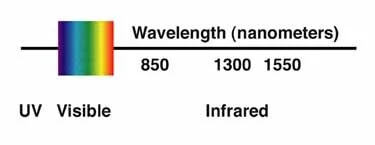
A CWDM SFP module transmits and receives on one fixed CWDM wavelength. Instead of the common 850 nm, 1310 nm, or 1550 nm windows, CWDM optics are spread across a wider grid, nominally 1270 nm to 1610 nm. Each module occupies a single wavelength channel; when several modules on different wavelengths feed a CWDM MUX/DEMUX, their signals share one single-mode fiber link.
In practice, three characteristics define the module:
- It operates on one fixed CWDM wavelength.
- It uses a standard SFP or SFP+ electrical interface, depending on the data rate.
- It normally works alongside passive CWDM MUX/DEMUX hardware when multiple wavelengths share one fiber route.
A single CWDM pair can run as a plain point-to-point link, but CWDM earns its keep when several wavelengths are combined onto the same fiber pair.
How a CWDM SFP Module Works in a Fiber Link
A CWDM system separates traffic by colour of light. Rather than one optical signal per fiber pair, different services or links are assigned to different wavelengths and then combined:
- A switch or router drives an electrical signal into the CWDM SFP module.
- The module converts it to light at a fixed wavelength, for example 1470 nm or 1550 nm.
- A CWDM multiplexer combines several wavelengths into one composite optical signal.
- The combined signal travels across single-mode fiber.
- A CWDM demultiplexer splits the wavelengths apart at the far end.
- The matching module receives its own wavelength and converts the light back to electrical data.
The transceiver handles electrical-to-optical conversion; the CWDM MUX/DEMUX handles combining and separating wavelengths. Because that multiplexer is passive, it needs no power, software, or active wavelength control. That passivity is the main reason CWDM is chosen to raise fiber utilisation without the operational overhead of a DWDM transport layer.

CWDM Wavelengths Explained
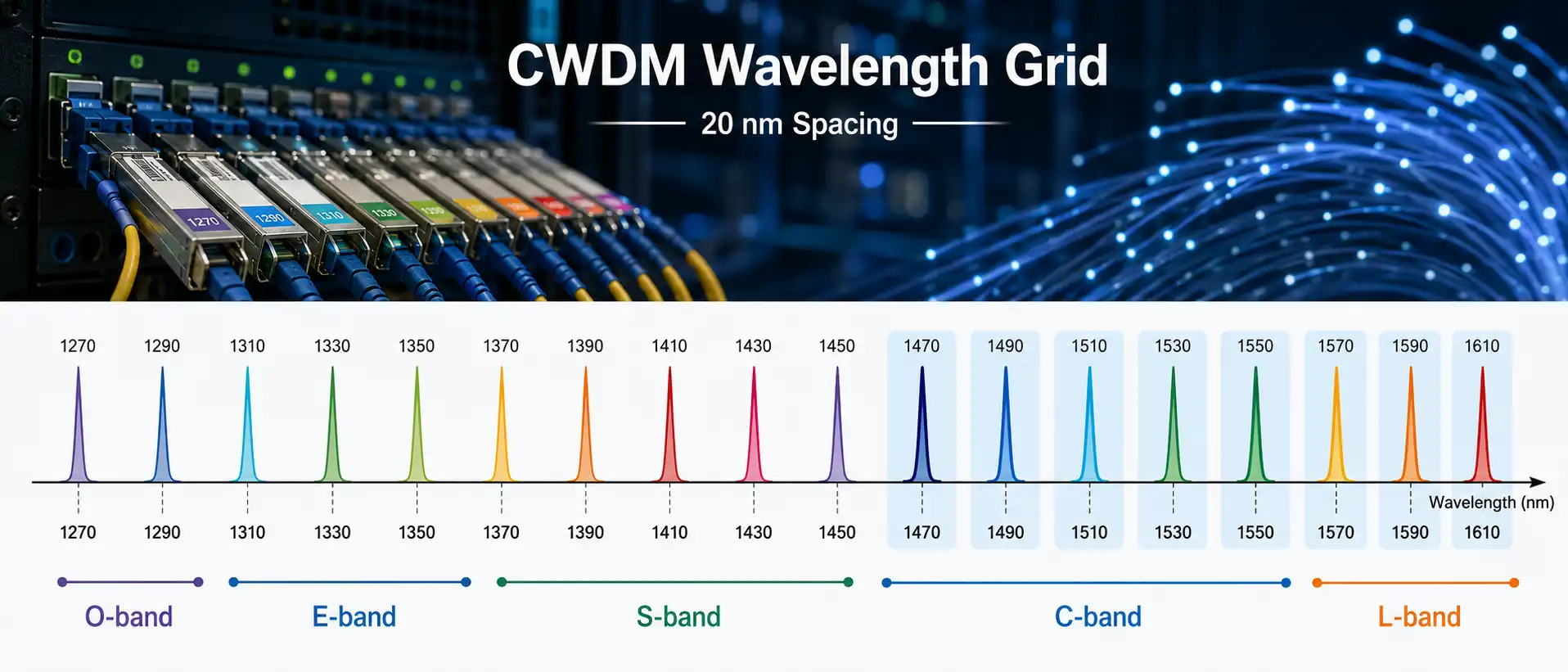
Wavelength planning is the part of CWDM that most often decides whether a deployment succeeds. The coarse grid is defined by the ITU-T G.694.2 recommendation, which sets a 20 nm channel spacing and a nominal range of 1270 nm to 1610 nm. The wide spacing is exactly what lets CWDM use simpler, uncooled optics and passive filters instead of the tightly controlled lasers a dense grid requires. Full specifications are published in the ITU-T G.694.2 standard.
CWDM SFP Wavelength Chart

| Nominal wavelength | ITU band | Typical use / note |
|---|---|---|
| 1270 nm | O-band | Available on all single-mode fiber; common in 8-channel low-band plans |
| 1290 nm | O-band | Low-band channel |
| 1310 nm | O-band | Overlaps the classic 1310 nm window |
| 1330 nm | O-band | Low-band channel |
| 1350 nm | O-band | Low-band channel |
| 1370 nm | E-band | Near the legacy water-peak region; verify fiber type |
| 1390 nm | E-band | Highest legacy water-peak loss on older fiber |
| 1410 nm | E-band | E-band channel; verify fiber type |
| 1430 nm | E-band | E-band channel; verify fiber type |
| 1450 nm | E-band | E-band channel; verify fiber type |
| 1470 nm | S-band | Start of the most commonly deployed range |
| 1490 nm | S-band | Widely used 8-channel plan member |
| 1510 nm | S-band | Widely used 8-channel plan member |
| 1530 nm | C-band | Low attenuation; widely deployed |
| 1550 nm | C-band | Lowest-loss window; widely deployed |
| 1570 nm | L-band | Low attenuation; long-reach friendly |
| 1590 nm | L-band | Long-reach friendly |
| 1610 nm | L-band | Top of the CWDM grid |
One practical detail is worth flagging before you commit to a channel plan. On older G.652 fiber, the E-band channels between roughly 1370 nm and 1450 nm sit on the "water peak," where attenuation is much higher, so many deployments simply avoid them and start at 1470 nm. Low-water-peak fiber that conforms to G.652.C or G.652.D largely removes that peak and lets all 18 channels carry traffic. If a design depends on the lower channels, confirm which fiber generation is actually in the ground.
Why Wavelength Matching Matters
For a link to come up, the module wavelength must match the channel on the MUX/DEMUX. If one end uses a 1470 nm module, that signal has to enter the 1470 nm port locally and exit the 1470 nm port remotely. Plug it into the wrong port and the link stays dark even when distance, connector, and switch are all correct. It is worth understanding how the ports on a CWDM MUX/DEMUX map to wavelengths before patching, because this is the single most common cause of a "new CWDM link that won't pass traffic."
Good documentation prevents most of this. For every link, record the service or port name, the local device and port, the remote device and port, the CWDM wavelength, the MUX/DEMUX port, the fiber route, and the module data rate and reach. That one record saves hours later.
Key Specifications to Check Before Buying CWDM SFP Modules
A module should never be chosen by wavelength alone; the right choice depends on the whole link. Different readers weigh these specs differently: a network engineer focuses on the optical budget and the wavelength map, a buyer confirms coding, reach, temperature, and connector type, and an IT manager is really asking whether CWDM is cheaper than installing new fiber. All three views are covered below.
Data Rate and Form Factor
Common options are 1G CWDM SFP for Gigabit access and aggregation, and 10G CWDM SFP+ for campus backbone, metro Ethernet, and data center interconnection. The form factor must match the port: a 10G SFP+ slot needs a 10G SFP+ module, not a 1G SFP.
Above 10G, be careful with the word "CWDM." Higher-speed links may use SFP28, QSFP+, or QSFP28 optics, and a term like "CWDM4" refers to a four-lane 100G optical architecture rather than the classic 20 nm CWDM SFP grid described here. If a 25G, 40G, or 100G design is in scope, check the exact optical standard the equipment expects rather than assuming every "CWDM" optic interoperates.
Transmission Distance and Optical Budget
Distance ratings such as 10 km, 20 km, 40 km, or 80 km are only starting points. The real question is whether the optical power budget can absorb every loss in the path. Following the Fiber Optic Association's loss-budget method, add up fiber attenuation over the full length, connector loss, splice loss, patch-panel loss, the insertion loss of the CWDM MUX and DEMUX, and an engineering margin for ageing and maintenance, then compare that total against the module's rated budget.
A short worked example makes the point. Take a 20 km single-mode route at roughly 0.35 dB/km, which is about 7 dB of fiber loss. Add a few connections at about 0.5 dB each, the insertion loss of the CWDM MUX/DEMUX pair (read the actual figure from the datasheet, as passive multiplexers add real loss), and the commonly used 3 dB margin for transmitter ageing and future repairs. The fiber distance is the easy part; once the passive devices and margin are included, a module merely "rated for 20 km" may not have enough budget for that specific link.
Fiber Type and Connector
CWDM SFP modules are designed for single-mode fiber, and most use duplex LC interfaces, though the exact connector should always be checked against the module datasheet and the patching environment. As noted earlier, the fiber generation also affects which channels are usable. On connector polish, do not assume compatibility: in many transceiver deployments UPC or PC patch cords are used, while APC may not be supported by the transceiver interface. Match the polish across the module, patch cord, adapter, and MUX/DEMUX port rather than mixing them and hoping.
DOM/DDM Monitoring
DOM or DDM lets the switch read live operating values: transmit optical power, receive optical power, module temperature, supply voltage, and laser bias current. This is especially useful on CWDM links because many channels share one fiber. When a channel becomes unstable, the DDM/DOM readings help tell whether the cause is low receive power, excess loss, wrong patching, or a failing module, instead of guessing.
Switch Compatibility and Coding
Even with the correct form factor, switch compatibility still matters. Some switches require vendor-specific coding, firmware support, or particular port configuration. Before ordering, confirm the switch brand and model, port speed, required coding, DOM/DDM support, operating temperature, supported distance, and any MSA or vendor compatibility requirement. This step matters most for replacements, mixed-vendor networks, and third-party compatible optics, so when in doubt, verify against the switch vendor's compatibility list and the transceiver supplier's coding options.
CWDM SFP vs Standard SFP vs BiDi SFP vs DWDM SFP
The four options solve different problems.
| Option | Best for | Main advantage | Main limitation |
|---|---|---|---|
| Standard SFP | Simple point-to-point links | Lowest complexity | One link per fiber pair |
| BiDi SFP | Saving a fiber strand on one link | Uses a single fiber instead of two | Usually one bidirectional link, not multi-channel growth |
| CWDM SFP | Several links over existing single-mode fiber | Good balance of capacity, simplicity, and cost | Needs wavelength planning and a MUX/DEMUX for multi-channel use |
| DWDM SFP | High-density or long-haul transport | Much higher channel density and amplifiable reach | Higher cost and greater optical design complexity |
Choose standard SFP when fiber is plentiful and the design is simple, BiDi when the goal is to save one strand on a single link, CWDM when several independent links must share one route, and DWDM when you need high channel counts, amplified long-haul reach, or carrier-grade scaling. For a deeper look at where the two multiplexing approaches diverge on spacing, cost, and complexity, see this comparison of how CWDM and DWDM differ.
CWDM SFP Selection Matrix
For common situations, this matrix maps a need to a sensible starting configuration and the one check that most often gets missed.
| Your situation | Reasonable starting point | Key check |
|---|---|---|
| Campus 10G uplinks, fiber-constrained | 10G CWDM SFP+ with a 4- or 8-channel MUX/DEMUX | Optical budget across the full path, with margin |
| Single fiber strand available | Single-fiber CWDM design (transmit and receive on the same strand) | Confirm the MUX/DEMUX is the single-fiber variant |
| Around 40–80 km metro link | Higher-reach CWDM module, ideally on C/L-band channels | Whether the budget closes without amplification |
| Mixed-vendor switches | Coded or coding-flexible CWDM optics | Required coding and DOM support per switch |
| Room to grow later | 8-channel MUX/DEMUX, populate a few wavelengths now | Reserve and document unused channels |
Common Use Cases for CWDM SFP Modules
The table below pairs each typical environment with a representative setup and the risk to watch.
| Scenario | Typical need | Representative CWDM setup | Key risk |
|---|---|---|---|
| Campus backbone | Multiple uplinks over limited inter-building fiber | Several 1G/10G channels on a shared fiber pair | Underestimating MUX/DEMUX insertion loss |
| Metro Ethernet and aggregation | Longer reach than campus, without DWDM complexity | A handful of service channels over a metro route | Reach limits without optical amplification |
| Data center interconnection | Add capacity on existing single-mode fiber | Moderate channel count, passive multiplexing | Channel count outgrowing the chosen MUX |
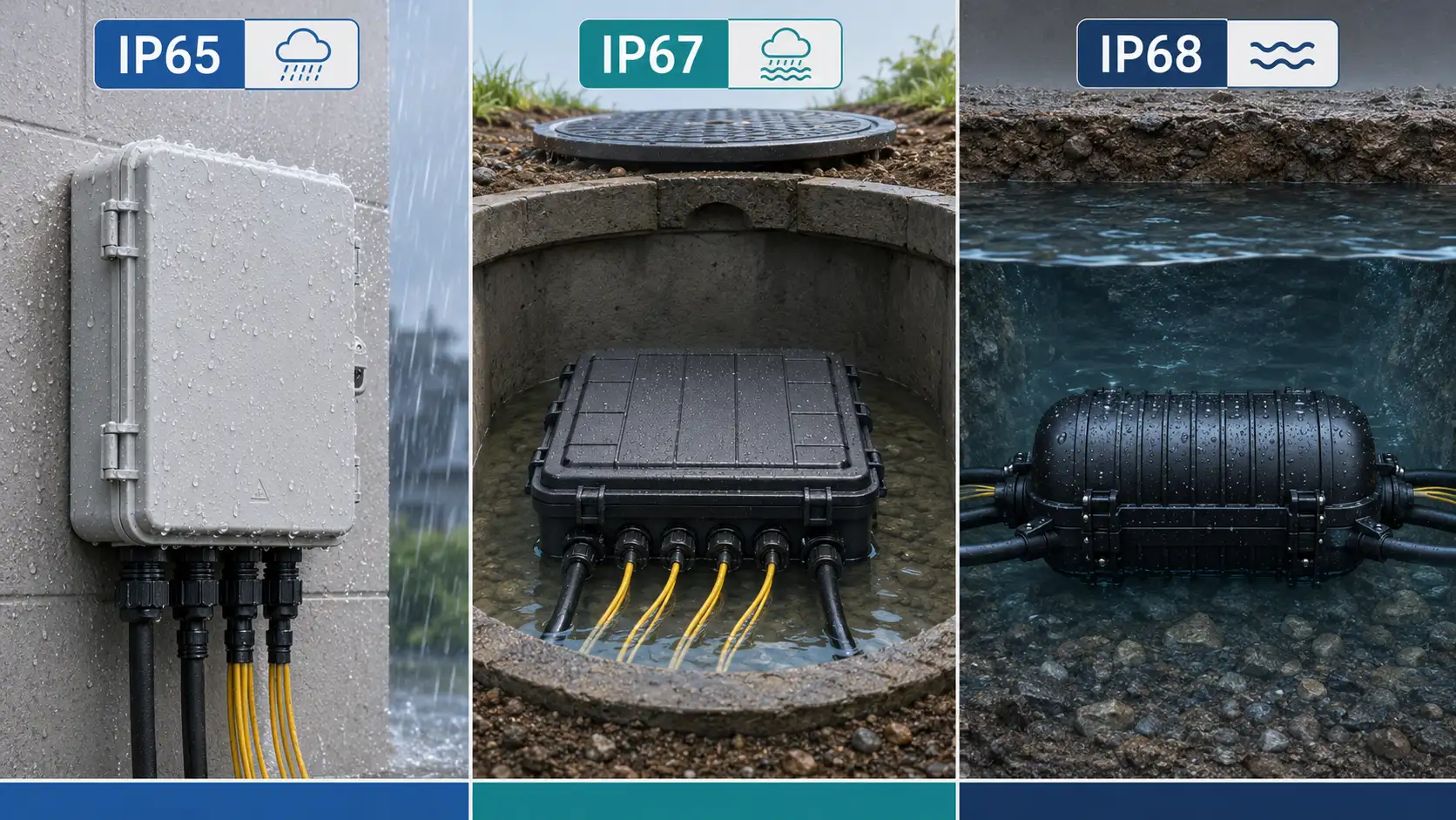
| Utility and industrial | Separate services on long, fiber-scarce routes | Monitoring, control, security on different wavelengths | Harsh-environment temperature range of optics |
The data center case is common enough to call out: where existing single-mode fiber is available and the required channel count is moderate, CWDM adds capacity without deploying an active transport platform, which is often exactly what a short- to medium-distance data center interconnect (DCI) needs.
When Should You Not Use a CWDM SFP Module?
Choosing well also means knowing when CWDM is the wrong tool. Reconsider it when any of the following is true:
- You need very long, amplified spans. The CWDM grid is spaced too widely to be amplified by standard erbium-doped fiber amplifiers, which practically caps unamplified CWDM reach in the tens of kilometres; this amplification constraint is described in the overview of wavelength-division multiplexing. Long-haul or amplified networks point toward DWDM.
- You need very high channel density. Eighteen channels is the CWDM ceiling; dense channel plans need DWDM.
- It is a single, simple point-to-point link with spare fiber. A standard or BiDi SFP is cheaper and simpler, with no MUX/DEMUX to buy.
- The budget cannot absorb passive multiplexer loss. If the optical budget is already tight, adding a MUX/DEMUX pair may push the link past its limit.
How to Choose the Right CWDM SFP Module
- Confirm the link speed. Decide on 1G, 10G, or another rate, and match the module form factor to the device port.
- Confirm the fiber route. Check that the route is single-mode and whether you have a fiber pair or a single strand; dual-fiber and single-fiber CWDM designs differ.
- Select the channel plan. Choose the wavelengths needed now and reserve channels for growth, for example a 4-channel design now on an 8-channel MUX/DEMUX.
- Match module wavelengths to MUX/DEMUX ports. Every wavelength must line up with its port; do not mix a 1470 nm and a 1490 nm module on the same intended channel.
- Calculate the optical budget. Sum fiber, connector, splice, and MUX/DEMUX loss plus margin, then compare with the module budget.
- Verify switch compatibility. Confirm coding, supported speed, DOM/DDM, and firmware limits before ordering.
- Document and commission the link. Keep a wavelength map, and during turn-up record each channel's receive power. Guidance on installing and commissioning a CWDM MUX/DEMUX system covers the patching and verification sequence.

Practical Deployment Example
Consider two campus buildings joined by one existing single-mode fiber pair. The team needs four independent 10G links, but trenching new fiber would be slow and expensive. A workable CWDM design might use four 10G CWDM SFP+ modules at each building, a 4-channel CWDM MUX at one end and a 4-channel DEMUX at the other, four wavelengths such as 1470, 1490, 1510, and 1530 nm, and documented duplex LC patching.
Before handover, a short commissioning checklist keeps the link honest: confirm each module is in its matching MUX/DEMUX port, measure and log the receive power per wavelength, verify the figures sit comfortably inside the module's sensitivity range, and store the wavelength map with the as-built records. A field note from this kind of build: when one channel came up but a second stayed dark, the cause was a 1490 nm module patched into the 1510 nm port. Nothing was faulty, the wavelength simply could not pass the wrong filter, and the logged Rx readings made the mismatch obvious in minutes.
Common Mistakes to Avoid
- Right speed, wrong wavelength. A 10G CWDM SFP+ still fails if its wavelength does not match the MUX/DEMUX channel.
- Ignoring MUX/DEMUX insertion loss. Passive multiplexers add loss that must be in the optical budget.
- Treating a distance rating as a guarantee. A 40 km rating does not promise success on every 40 km link; real fiber loss and patching decide.
- Mixing connector types carelessly. Mismatched polish or adapters cause high reflection, poor mating, or physical incompatibility.
- Skipping DOM/DDM baselines. Record transmit and receive power while the link is healthy so future troubleshooting has a reference point.
FAQ
Q: What does CWDM mean in a CWDM SFP module?
A: CWDM stands for Coarse Wavelength Division Multiplexing. It lets different optical wavelengths carry separate data channels over the same fiber route.
Q: Does a CWDM SFP module require a MUX/DEMUX?
A: If you use a single CWDM wavelength as a point-to-point link, a MUX/DEMUX may not be needed. To combine multiple wavelengths on one fiber, a CWDM MUX/DEMUX is required.
Q: How many CWDM channels can one fiber carry?
A: The ITU-T G.694.2 grid defines up to 18 channels from 1270 nm to 1610 nm at 20 nm spacing. On older fiber, the E-band channels are often skipped, so many deployments use the 8 to 16 channels in the higher, lower-loss range.
Q: What is the difference between a 1470 nm and a 1490 nm CWDM SFP?
A: They are simply different channels on the grid. Each must be matched to its own MUX/DEMUX port; they are not interchangeable, and swapping them is a frequent cause of a link that will not pass traffic.
Q: Can I mix CWDM SFP modules from different vendors?
A: Often yes, as long as the wavelength, reach, coding, and DOM behaviour are compatible with the switch and the MUX/DEMUX. Confirm coding against the switch vendor's list and the supplier's coding options before mixing.
Q: What happens if I use the wrong CWDM wavelength?
A: The signal will not pass the corresponding MUX/DEMUX filter, so the link stays down even though the optics may be perfectly healthy. Checking the logged receive power usually reveals the mismatch quickly.
Q: Can I use CWDM SFP modules with multimode fiber?
A: No. CWDM SFP modules are designed for single-mode fiber and are not the right choice for standard multimode short-reach links.
Q: What is the difference between CWDM SFP and DWDM SFP?
A: CWDM uses wider 20 nm spacing and simpler optics, which suits cost-sensitive medium-capacity links. DWDM uses much narrower spacing, supports many more channels, and can be amplified for high-density or long-haul networks.
Q: How do I choose which CWDM wavelength to use?
A: Base the choice on the MUX/DEMUX channel plan, current link requirements, and room for future expansion, and make sure the same wavelength is mapped correctly all the way through the system.
Q: Do CWDM links need optical amplifiers?
A: Usually not, but that is also a limit: the CWDM grid cannot use standard EDFA amplification, so very long spans are better served by DWDM.