Optical signal management in modern hyperscale facilities presents a challenge that often goes unnoticed until equipment fails. The fiber optic attenuator-a passive component designed to reduce optical power in a controlled manner-serves as the unassuming workhorse that prevents receiver saturation, bit error rate degradation, and premature transceiver burnout. While amplifiers and multiplexers receive disproportionate engineering attention, attenuators remain the silent arbiters of power budget compliance across short-reach interconnects.
The Problem Nobody Talks About
Here's something that catches even experienced engineers off guard. You spec out a beautiful 100G link, install brand-new QSFP28 transceivers, run pristine OM4 fiber across a 15-meter patch-and suddenly you're seeing errors. Not many, but enough. The link flaps occasionally. The logs show CRC failures that spike during peak traffic.
The culprit? Too much light.
Modern transceivers-particularly SR4 and short-wave modules-pump out optical power optimized for their maximum rated distance. When that 100-meter-rated transceiver only needs to reach 8 meters, the receiving photodiode gets hammered with more photons than it can linearly process. The detector saturates. Signal integrity collapses. And because "too much signal" isn't something most troubleshooting flowcharts consider, teams waste hours chasing phantom cable faults.
What Attenuators Actually Do
The mechanism is straightforward. An attenuator introduces a calibrated amount of optical loss-measured in decibels-to bring received power into the transceiver's specified sensitivity window. Think of it as sunglasses for fiber. The underlying physics varies by design: some use air gaps that create Fresnel reflection losses, others employ absorptive doped glass, and a few rely on precise fiber misalignment in a ferrule.
The gap-based approach (sometimes called "inline" or "plug-style") dominates data center deployments. A small air gap between connector end-faces introduces predictable loss-typically 3dB to 10dB for fixed attenuators. Variable optical attenuators (VOAs) offer adjustable attenuation through mechanical or MEMS-based mechanisms, though their added complexity and cost limit adoption to specialized applications like DWDM channel equalization.
Most engineers I've worked with default to 5dB attenuators as their go-to. It's not always the right choice, but it's rarely catastrophically wrong.
The Numbers Matter
A quick refresher on optical power budgets, since this is where miscalculations happen. Every transceiver datasheet specifies a transmit power range (say, -1 to +2 dBm) and a receiver sensitivity window (perhaps -11.5 to +2.4 dBm for a 25G SR device). The difference between your actual transmit power and minimum receiver sensitivity constitutes your link budget. Connector losses, cable attenuation, splice losses-they all subtract from this margin.
But the maximum receiver input-that +2.4 dBm ceiling-matters equally. Exceed it, and you're overdriving the detector. Most spec sheets list an "overload" threshold somewhere beyond the max sensitivity, but operating in that gray zone invites trouble. This is where attenuators earn their keep.
Say you're measuring +1 dBm at the receiver with a 3-meter patch cord. Your receiver's optimal range tops out at +1 dBm for linear operation, but you're seeing intermittent bit errors. Adding a 3dB attenuator drops received power to -2 dBm-comfortably within spec. Problem solved, and you've spent maybe $8.

Real Deployment Scenarios
Data centers aren't homogeneous. A colocation provider's meet-me room operates under different constraints than a hyperscaler's leaf-spine fabric. Attenuator use cases vary accordingly.
Intra-rack connections. This is the bread-and-butter scenario. Servers connecting to top-of-rack switches via 1-meter or 2-meter DAC cables don't usually need attenuators-the cables themselves provide adequate loss. But when fiber replaces copper (increasingly common with 100G+ speeds and the push toward structured cabling), those sub-5-meter runs become problematic. High-power SR transceivers feeding directly into adjacent ports create the saturation issues described earlier.
Staged equipment testing. Before production deployment, operations teams validate switches and routers on bench setups. These test configurations often use direct back-to-back fiber connections-effectively zero-loss paths that guarantee receiver overload. Attenuators let engineers simulate production link losses without stringing 300 meters of fiber across the lab.
I've seen attenuators duct-taped to workbenches in a dozen labs. Not pretty, but functional.
Legacy equipment integration. Brownfield data centers inevitably contain equipment from multiple generations. A 10G SFP+ receiver designed a decade ago might have a narrower dynamic range than contemporary 25G transceivers. When these older receivers connect to modern higher-power transmitters, attenuators bridge the gap without requiring transceiver replacement.
CWDM/DWDM systems. Wavelength-division multiplexed architectures demand tight channel power balancing. A 3dB variation between adjacent channels degrades OSNR and stresses EDFAs. Per-channel VOAs-or fixed attenuators during commissioning-level the playing field. This gets into territory beyond simple plug-and-play attenuator use, but the principle remains identical.
A Word on Connector Types
LC dominates modern data center optics. SC still appears in legacy installations and certain carrier equipment. FC shows up occasionally in test setups. MTP/MPO connectors serve parallel optics-40G SR4, 100G SR4, and their successors-but attenuating multi-fiber connections adds complexity. You'll typically see MTP attenuators used at the cassette level rather than individual fibers. Match your attenuator connector to your infrastructure. Seems obvious, but mismatched adapters create insertion loss variations that complicate power budget calculations.

What Goes Wrong
Attenuators aren't complicated devices, but they're remarkably easy to misuse.
Over-attenuation ranks first. An engineer sees receiver errors, assumes saturation, installs a 10dB attenuator-and now the signal is too weak. The link still doesn't work, but now for the opposite reason. Always measure actual received power before selecting attenuation values.
Dirty connectors are the other classic failure mode. Attenuators add connector interfaces to the link. Each interface is an opportunity for contamination. A microscopic dust particle on an APC ferrule end-face creates unpredictable loss that shifts with temperature and vibration. Clean every connector. Every time. No exceptions.
I'll mention one more: forgetting attenuators are there. Documentation fails, the link gets troubleshot years later, and nobody remembers that 7dB attenuator buried in the patch panel. Suddenly an upgrade that changes transmit power "mysteriously" breaks a link that worked for five years. Label everything.
Procurement Realities
Fixed attenuators cost almost nothing-$5 to $15 for basic LC units from reputable manufacturers. Buy them in bulk. Keep a drawer full in the networking lab. The 1dB, 3dB, 5dB, 7dB, and 10dB values cover 95% of scenarios. Variable attenuators run $50 to $300+ depending on resolution and connector type; reserve these for calibration or tunable applications.
Brand matters less than you'd think. The physics of a controlled air gap or absorptive element doesn't vary dramatically between vendors. That said, avoid no-name sellers on marketplace sites-inconsistent attenuation tolerances and poor return loss specifications will cause headaches. Corning, Thorlabs, and FS.com produce reliable product. CommScope's fiber accessories work well if you're already in their ecosystem.
The Hidden Benefit: Standardization
Here's something that doesn't make it into most technical discussions. Attenuators enable standardization at scale.
Hyperscale operators purchase transceivers by the tens of thousands. Managing multiple transceiver SKUs for different link distances-10m versus 300m, say-creates procurement complexity, inventory headaches, and sparing nightmares. Instead, standardize on a single high-power transceiver rated for maximum distance, then attenuate shorter links as needed. The attenuator cost is trivial compared to the operational efficiency gained from uniform transceiver fleets.
This approach also simplifies troubleshooting. Every transceiver behaves identically. Power budgets become predictable. Swap any port for any other during outages. The elegance compounds as networks scale.
Wavelength Considerations
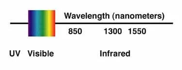
Most attenuators specify operation at 850nm, 1310nm, 1550nm, or some combination. Multimode deployments typically use 850nm (SR optics). Single-mode splits between 1310nm (intermediate reach, LR) and 1550nm (extended reach, ER, and DWDM). Attenuation values vary slightly across wavelengths for absorptive-type devices-a 5dB attenuator at 1310nm might measure 5.3dB at 1550nm. For critical applications, verify specifications match your operating wavelength.
Closing Thoughts
Fiber optic attenuators won't revolutionize your data center. They're not exciting. They don't show up in vendor pitch decks or architecture diagrams. But they solve a genuine problem-receiver saturation in short-reach links-cheaply and reliably. They enable transceiver standardization strategies that reduce operational overhead at scale. They make equipment testing practical.
Keep a stock of common values. Measure before installing. Document what you deploy. Clean your connectors. That's really all there is to it.
Sometimes the simplest components matter most.