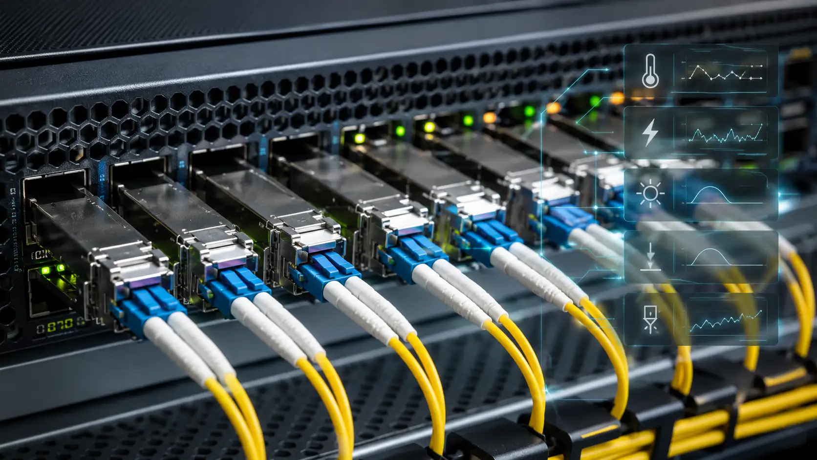
A fiber optic coupler is a passive optical component that splits, combines, taps, or redistributes light between optical fibers. In real-world networks, couplers let one signal reach many users, allow several signals to share one fiber path, or sample a small amount of light for monitoring. They are quiet workhorses inside FTTH access nodes, data centers, test setups, fiber lasers, and sensor systems.
Before going further, it is worth clearing up a common confusion. A coupler is not the same as a fiber optic adapter. An adapter mechanically aligns two connectors so light can pass through; a coupler actively changes how optical power is distributed between ports. RP Photonics defines fiber couplers as devices that couple light from one or several input fibers to one or several output fibers, with a power distribution that can depend on wavelength and polarization.
This guide explains how fiber optic couplers work, the main types you will encounter, the specifications that matter when buying, and how to make a sensible selection for your project.

What Is a Fiber Optic Coupler?

A fiber optic coupler is an optical device with one or more input ports and one or more output ports. Depending on the design, it can do several things at once:
- Split one input signal into two or more outputs
- Combine multiple inputs into one output fiber
- Tap a small percentage of power for monitoring or testing
- Distribute optical signals across many ports in a star or tree pattern
- Combine or separate wavelengths in CWDM or DWDM systems
For example, a 1x2 coupler has one input and two outputs. A 2x2 coupler has two inputs and two outputs and can act as either a splitter or a combiner depending on the direction of the light.
In telecom and data network discussions, the terms fiber optic coupler, optical splitter, and optical combiner often overlap. A splitter is essentially a coupler used in the splitting direction, while a combiner is the same device used in the combining direction. If you are sourcing components, the names on the datasheet usually depend on how the device is intended to be deployed.
How Does a Fiber Optic Coupler Work?
A coupler works by transferring optical power between fiber paths. The exact mechanism depends on the manufacturing approach.
In a fused biconical taper (FBT) coupler, two or more fibers are heated, pulled, and fused so their cores come close enough for light to leak from one core into another over a controlled length. RP Photonics explains that fused couplers are made by thermally tapering and fusing fibers so their cores are brought into close optical contact.

In a planar lightwave circuit (PLC) splitter, light is guided through a waveguide circuit fabricated on a silica or polymer substrate. This is the dominant approach for high-port-count splitters because the geometry of the waveguide is highly repeatable.
Splitting Optical Power
When a coupler splits light, the input optical power is divided among the output ports. In an ideal 1x2 50/50 coupler, each output receives half of the input power. In decibel terms, that means roughly 3 dB of theoretical loss per output before any real-world losses are added. The Fiber Optic Association (FOA) notes that splitting introduces an additional 3 dB of loss for every doubling of the split count, plus a small excess loss from the coupler structure.
Combining Optical Signals
Many couplers are bidirectional. A device that splits power in one direction can also combine power in the reverse direction. In a passive optical network (PON), downstream traffic from the OLT is split toward many users, while upstream signals from those users are combined back toward the OLT through the same passive splitter.
Why Couplers Always Introduce Loss
Loss in a fiber optic coupler comes from several sources working together:
- Theoretical split loss (the unavoidable share of power)
- Excess loss from the coupler structure itself
- Connector and splice loss at the input and output ports
- Wavelength mismatch between the device and the system wavelength
- Polarization-dependent loss (PDL)
- Non-uniform power distribution between output ports
This is why selecting a coupler is never just about the port count. The loss budget, wavelength range, split ratio, and environment all need to be checked together.

Main Fiber Optic Coupler Types
Couplers can be classified in several useful ways. The right classification depends on whether you are designing a network, sourcing components, or troubleshooting a link.

By Function: Splitter, Combiner, Tap, and WDM Coupler
An optical splitter divides one input into multiple outputs (1x2, 1x4, 1x8, 1x16, 1x32, 1x64). A combiner merges multiple inputs into a single output. A tap coupler sends most of the optical power through the main path and diverts a small fraction (typical ratios are 90/10, 95/5, and 99/1) to a monitoring port. A WDM coupler combines or separates signals based on wavelength, used heavily in CWDM and DWDM systems.
By Port Configuration: 1x2, 2x2, 1xN, and Star Couplers
A 1x2 fiber optic coupler has one input and two outputs and is the most common building block for simple splitting or tapping. A 2x2 coupler with two inputs and two outputs is widely used in bidirectional systems, interferometers, and test setups. A 1xN splitter serves PON, FTTH, CATV, and distribution networks. An NxN star coupler distributes optical power across many input and output paths simultaneously.
By Shape: Y, T, X, Star, and Tree Couplers
A Y coupler splits one input into two balanced outputs. A T coupler usually has an uneven ratio such as 90/10 or 80/20 and is well suited to signal monitoring. An X coupler is normally a 2x2 device. A star coupler distributes power between multiple inputs and outputs. A tree coupler splits one input into many outputs in a branching structure and is the standard choice for PON and FTTx networks.
By Manufacturing Method: FBT vs PLC vs Micro-Optics
An FBT coupler (fused biconical taper) is made by fusing and tapering fibers together. It is well suited to small split counts, custom split ratios, and cost-sensitive designs. A PLC splitter uses a waveguide chip, which gives better wavelength uniformity and tighter tolerances at high port counts. Micro-optics couplers use lenses, prisms, mirrors, or thin-film filters and tend to appear in specialized optical instruments rather than telecom cabling.

FBT Coupler vs PLC Splitter: Which One Should You Choose?
The FBT versus PLC question comes up on almost every coupler purchase order. The honest answer is that neither one is universally better; they have different sweet spots.

FBT couplers shine when the design calls for a low split count (typically 1x2 to 1x8), a custom split ratio (such as 80/20, 90/10, or 95/5), or a single-wavelength application. They are generally cheaper for these simpler builds. PLC splitters are the safer bet whenever you need consistent performance at higher port counts (1x8 and above), wide wavelength operation across 1260–1650 nm, or stable behavior over a broad temperature range. Most modern fiber optic splitters deployed in FTTH and PON networks are PLC-based for exactly this reason.
In practice, FBT is the right choice for monitoring taps and bespoke ratios, while PLC is the default for FTTH distribution, passive optical LAN, and any high-uniformity requirement.
Key Specifications: Split Ratio, Insertion Loss, and Wavelength

Split Ratio or Coupling Ratio
The split ratio describes how power is divided. A 50/50 coupler splits power evenly. A 90/10 tap sends 90% through the main path and 10% to the monitoring port. For monitoring you usually want to remove only a small slice of light; for distribution you typically want equal splitting.
Insertion Loss and Excess Loss
Insertion loss is the total optical power lost when the coupler is placed into the link. It includes the theoretical split loss and the device's own excess loss. A 1x2 50/50 splitter has a theoretical 3 dB split loss, but real datasheets usually show typical insertion loss of around 3.4–3.8 dB once excess loss and connector loss are added. Excess loss is the additional loss beyond the unavoidable split loss; a lower number means a better-built coupler.
Uniformity, Return Loss, and Directivity
Uniformity describes how evenly power is distributed across the output ports and becomes critical at 1x8, 1x16, 1x32, and 1x64 splits. Return loss measures reflected light traveling back toward the source. Directivity indicates how well the device prevents power from leaking into the wrong port. These three matter most in DWDM systems, OTDR test environments, fiber lasers, and any link where stray reflections degrade performance.
Operating Wavelength and Bandwidth
The coupler must match your system wavelength. Telecom systems commonly use 1310 nm, 1490 nm, and 1550 nm windows; PON networks add 1577 nm and 1490 nm based on the relevant ITU-T G.984 and G.987 specifications. Some couplers are designed for a narrow window only, while wideband PLC splitters cover 1260–1650 nm.
Fiber Type, Connector, and Package
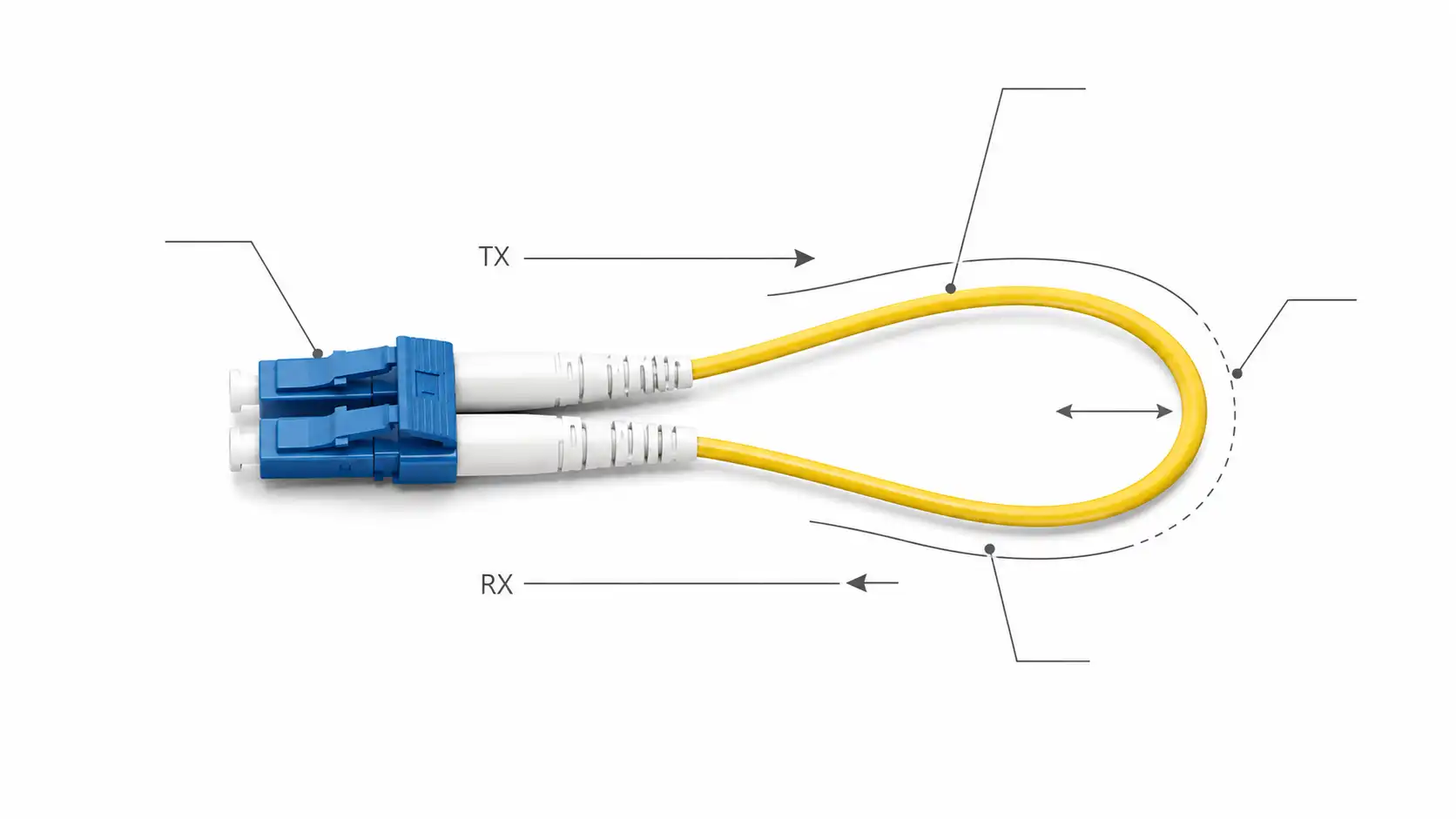
Confirm whether the coupler supports single-mode or multimode fiber, and double-check the connector type and polish. Common fiber optic connector options include LC, SC, FC, ST, and MTP/MPO, with UPC or APC polish. APC is preferred wherever low back reflection matters, especially in PON and analog video systems. Mechanical packaging matters too: bare fiber, blockless mini module, ABS box, LGX cassette, rack-mount enclosure, and outdoor IP68 closure all serve different deployment scenarios.
Common Applications of Fiber Optic Couplers

PON, FTTH, and Passive Optical LAN
PON networks use 1xN splitters to connect one OLT port to many ONTs. Downstream traffic is distributed to users; upstream traffic is combined back. The same passive device handles both directions. Passive optical LANs use the same architecture in office and campus environments. The FOA notes that a single OLT port can serve up to 32 (and sometimes 64 or 128) devices through cascaded splitters, depending on the optical power budget.
Monitoring and Test Points
Tap couplers sample a small fraction of the light without breaking the main link. For a live single-mode link, a 99/1 or 95/5 tap is far more appropriate than a 50/50 splitter, which would consume too much budget on the main path.
WDM and DWDM Systems
WDM couplers combine or separate signals at different wavelengths. They are essential in long-haul telecom, fiber amplifiers (EDFAs), and any system where multiple optical channels share one fiber. CWDM uses a 20 nm grid; DWDM uses a 100 GHz or 50 GHz grid that requires tighter wavelength tolerance from every component.
Lab, Sensor, and Laser Systems
Fiber couplers also appear in interferometers, OCT systems, fiber sensors, and high-power fiber lasers. In these applications, polarization behavior and return loss often matter more than raw cost.
Application-to-Coupler Quick Reference
To make selection more concrete, here is how applications typically map to coupler types in practice. For FTTH and PON distribution, the standard answer is a PLC splitter in an ABS box or LGX cassette with 1x8, 1x16, or 1x32 ports. For live link monitoring, choose an FBT 99/1 or 95/5 tap coupler with APC connectors. For 2-channel bidirectional test setups, a 2x2 50/50 FBT coupler is usually sufficient. For CWDM/DWDM channel aggregation, a thin-film WDM coupler or AWG-based mux/demux is required. For fiber laser pump combining, a polarization-maintaining or specialty-fiber coupler is needed instead of a generic telecom device.
How to Choose the Right Fiber Optic Coupler
Use the following workflow before placing an order.
- Define the function. Decide whether you need to split, combine, tap, or wavelength-multiplex.
- Choose the port configuration. Select 1x2, 2x2, 1x8, 1x16, 1x32, 1x64, or NxN based on the number of endpoints.
- Confirm the split ratio. Use 50/50 for equal splitting, 90/10 or higher for monitoring, and uniform 1xN for distribution.
- Check the wavelength range. Match the coupler bandwidth to your system, including any future upgrade wavelengths.
- Calculate the loss budget. Add fiber attenuation + connector loss + splice loss + coupler insertion loss + safety margin (typically 3 dB).
- Match the fiber and connector. Confirm single-mode (G.652D or G.657) versus multimode (OM3/OM4/OM5), connector type, and polish.
- Plan the installation environment. Indoor cabinets, outdoor closures, data center racks, and lab benches need different packaging.
A Simple Loss Budget Example
Suppose you are designing a 1x16 PLC splitter link for FTTH with 2 km of single-mode fiber optic cable, four LC/UPC connector pairs, and one fusion splice. A reasonable estimate would be: 13.5 dB (typical 1x16 PLC insertion loss) + 0.6 dB (2 km × 0.3 dB/km at 1310 nm) + 1.2 dB (4 connectors × 0.3 dB) + 0.1 dB (one splice) + 3 dB (margin) ≈ 18.4 dB total. If your OLT/ONT power budget is Class B+ (28 dB), you have comfortable headroom; if it were tighter, you would need to reduce splices, shorten the run, or step down to a 1x8 split.

Common Mistakes to Avoid
The first and most common mistake is treating a coupler as a simple adapter. The two are unrelated devices with different jobs. The second is ignoring insertion loss and stacking too many splits onto a single link until the receiver runs out of power. The third is choosing FBT for an FTTH 1x32 deployment where PLC would be far more uniform and stable. The fourth is using a coupler designed for one wavelength window at another wavelength, which can produce very different real-world loss. The fifth is mixing UPC and APC connectors without thinking through the reflection consequences.
FAQ About Fiber Optic Couplers
What is the difference between a fiber optic coupler and a splitter?
A splitter is a coupler used to divide one input into multiple outputs. The term coupler is broader because it also covers combiners, taps, and wavelength multiplexers.
Is a fiber optic coupler passive or active?
Almost all telecom and cabling couplers are passive and require no electrical power. Only specialized devices like optical amplifiers and optical switches are considered active.
What does 1x2 mean in a fiber optic coupler?
A 1x2 coupler has one input port and two output ports. It is the simplest splitter or tap configuration.
What does 2x2 mean in a fiber optic coupler?
A 2x2 coupler has two inputs and two outputs and can act as either a splitter or a combiner depending on the signal direction. It is common in interferometers and bidirectional test setups.
How do I choose a split ratio for a tap coupler?
For most live-link monitoring, a 99/1 or 95/5 tap is the right choice because it removes only a small slice of optical power from the main path. A 90/10 tap is appropriate when the monitoring receiver is less sensitive. A 50/50 split is rarely the correct answer for monitoring.
What is the typical insertion loss of a 1x32 PLC splitter?
Most commercial 1x32 PLC splitter datasheets list typical insertion loss between 16.5 and 17.5 dB, including the theoretical 15 dB split plus 1.5–2.5 dB of excess and connector loss. Always check the specific datasheet for the model you are buying.
Can I use a single-mode coupler with multimode fiber?
Generally no. Single-mode couplers are designed around a 9 µm core; multimode fiber has a 50 or 62.5 µm core. Mixing the two causes significant mode-field mismatch and high coupling loss. Use a coupler that matches your multimode or single-mode fiber type.
Are fiber optic couplers bidirectional?
Most passive couplers are bidirectional. The same device used to split downstream light can combine upstream light when used in the opposite direction, which is exactly how PON networks operate.
What is the difference between a WDM coupler and a standard optical coupler?
A standard coupler distributes power without distinguishing wavelengths. A WDM coupler uses thin-film filters or AWG technology to separate or combine specific wavelengths, which is essential for CWDM and DWDM systems.
What connector type should I choose for a fiber optic coupler?
LC and SC are the most common in modern access and data center deployments. APC polish is preferred wherever back reflection matters, such as PON, RFoG, and analog video. Match the polish on both ends of the link; mixing UPC and APC will degrade performance.
Conclusion
A fiber optic coupler is a deceptively simple component that quietly underpins almost every modern optical network. Choosing the right one is a balance between port count, split ratio, wavelength range, insertion loss, fiber type, connector, and the environment where it will live. For a single monitoring tap or a custom split ratio, an FBT coupler is usually the most economical answer. For FTTH, PON, passive optical LAN, or any high-port-count distribution, a PLC splitter is the safer long-term choice. The best coupler is always the one that fits the optical power budget and reliability requirements of the network it serves, not simply the one with the lowest unit price.