A crossover LAN cable is an Ethernet cable that swaps the transmit and receive pairs so two similar devices can connect directly. You build one by wiring T568A on one end and T568B on the other, which crosses pins 1 and 2 with pins 3 and 6. On older 10/100 equipment a crossover was required to link like-to-like devices, such as PC to PC, switch to switch, or router to router. On almost all current hardware you no longer need one, because the ports detect the cable type automatically (a feature called Auto-MDI/MDIX). A crossover cable is still worth keeping on hand for legacy 10/100 gear, certain industrial controllers, and any port that does not support automatic detection.
The sections below give you the full RJ45 pinout, the difference between straight-through and crossover cables, a short decision checklist, how to identify and test a crossover cable, and the extra specifications that matter when you deploy one in a demanding industrial environment.
What Is a Crossover LAN Cable?
An Ethernet link uses one pair of wires to transmit (TX) and another to receive (RX). When you connect two different kinds of device - for example a computer to a switch - the transmit pin on one side naturally lines up with the receive pin on the other, so a normal straight-through cable works. When you connect two of the same kind of device, both sides try to transmit on the same pins, and nothing gets through.
A crossover cable solves that the old-fashioned way: it physically swaps the transmit and receive pairs inside the cable, so one device's TX reaches the other device's RX. Most of the Ethernet patch cables sold today are straight-through, because modern switches and network cards now correct the mismatch internally and a dedicated crossover cable is rarely necessary.
Crossover LAN Cable Pinout: T568A to T568B Wiring
RJ45 connectors are terminated to one of two color codes defined under the ANSI/TIA-568 standard: T568A and T568B. The two codes are identical except that the green and orange pairs are swapped. A straight-through cable uses the same code on both ends. A crossover cable uses T568A on one end and T568B on the other - and that mismatch is precisely what crosses the transmit and receive pairs.
The table below shows the full 8-pin RJ45 pinout for both codes:
| Pin | T568A color | T568B color | Signal (10/100 Ethernet) |
|---|---|---|---|
| 1 | White / Green | White / Orange | Transmit + (TX+) |
| 2 | Green | Orange | Transmit − (TX−) |
| 3 | White / Orange | White / Green | Receive + (RX+) |
| 4 | Blue | Blue | Unused on 10/100 |
| 5 | White / Blue | White / Blue | Unused on 10/100 |
| 6 | Orange | Green | Receive − (RX−) |
| 7 | White / Brown | White / Brown | Unused on 10/100 |
| 8 | Brown | Brown | Unused on 10/100 |
Reading the table, you can see what a crossover does in practice. On a 10/100 link only pins 1, 2, 3 and 6 carry data, so a crossover swaps the transmit pair with the receive pair: pin 1 goes to pin 3, pin 2 goes to pin 6, and the reverse on the other end. Gigabit Ethernet (1000BASE-T) uses all four pairs, so a true Gigabit crossover also swaps pins 4 and 5 with pins 7 and 8. If you are terminating cables yourself, accurate RJ45 termination is what determines whether the link passes - the color code only matters if both ends follow it consistently.

Straight-Through vs Crossover Cable
The two cable types look identical from the outside, so it helps to compare them side by side:
| Attribute | Straight-through cable | Crossover cable |
|---|---|---|
| Wiring | Same code on both ends (T568A–T568A or T568B–T568B) | T568A on one end, T568B on the other |
| Pairs | Transmit and receive stay in line | Transmit and receive pairs are swapped (1↔3, 2↔6) |
| Typical use | Connecting unlike devices: PC to switch, router to switch, device to wall jack | Connecting like devices: PC to PC, switch to switch, router to router (legacy) |
| Today's relevance | The default for almost every connection | Rarely required; Auto-MDI/MDIX handles it on most modern ports |
| Marking | Usually unmarked | Often printed "X-OVER" or "CROSSOVER", sometimes with red boots (common but not standardized) |
If you want a more detailed walkthrough of how the two differ in everyday use, see our companion article on crossover versus standard Ethernet cables.

When Do You Still Need a Crossover Cable?
For most people the honest answer is: probably never, on modern equipment. The reason is Auto-MDI/MDIX (Automatic Medium-Dependent Interface Crossover), a feature that lets a port sense whether it is connected to a straight-through or crossover cable and reconfigure its own transmit and receive pins to match.
It is worth being precise about how this works, because the details are often stated incorrectly. Auto-negotiation - the process by which two ports agree on speed and duplex - is required for 1000BASE-T (Gigabit) under IEEE 802.3. Auto-MDIX is a separate, related feature, and in the standard it is technically described as optional for 1000BASE-T; in practice, however, virtually every modern Gigabit interface implements it. The important caveat is that Auto-MDIX generally depends on auto-negotiation being enabled. If a port is hard-set to a fixed speed and duplex, auto-detection may stop working, and on some industrial controllers it can be disabled deliberately. In those cases the cable type matters again.
So you may still need a crossover cable when:
- You are connecting two like devices directly - PC to PC, two switches, hubs, or routers - and at least one port lacks Auto-MDIX.
- You are working with older 10/100 equipment that predates widespread Auto-MDIX support.
- An industrial controller or the device manual specifically calls for a crossover connection, or the port has auto-negotiation switched off.
- You are troubleshooting and want to remove cable auto-detection as a variable.
A simple way to decide: if both ports are modern and set to auto-negotiate, a straight-through cable will almost certainly link up. If either port is legacy or manually fixed, check the device manual - and when in doubt, a crossover cable will work in most "like-to-like" situations either way.
How to Identify and Test a Crossover Cable
Because crossover and straight-through cables are visually identical, do not rely on guesswork in a mixed inventory. There are three practical ways to tell them apart:
- Check the jacket print. Factory-made crossover cables from reputable suppliers are usually marked "X-OVER" or "CROSSOVER", and sometimes use red boots. Markings help, but they are a convention, not a guarantee.
- Inspect the connectors. Hold the two RJ45 plugs side by side with the clips facing away. On a straight-through cable the wire colors appear in the same order on both ends. On a crossover, the green and orange pairs are swapped on one end. Visual inspection catches the wiring pattern but will not reveal hidden termination faults.
- Use a tester. The reliable method is to test it with a network cable tester. A wire-map test shows the crossover pattern clearly - pins 1 and 2 mapping to 3 and 6 - and also confirms continuity and the absence of opens, shorts, or split pairs.
For installed runs that have to pass acceptance testing, a wire-map check is the minimum, and a certification-grade tester adds the performance margins that a simple continuity check cannot verify.

Advanced and Industrial Use Cases
Everything above covers the common networking questions. In industrial automation - robotic welding cells, packaging lines, motion control - the pinout is usually the easy part. What actually determines whether a crossover (or any patch cable) survives in the field is the rest of the specification: jacket material, shielding, connector sealing, and bend radius.
A few field-tested points worth verifying before you order:
- Shielding and EMI. Variable-frequency drives, servos, and welders generate strong electromagnetic interference. Unshielded cable in that environment can produce intermittent bit errors rather than a clean failure, which is far harder to diagnose. A shielded S/FTP cable, grounded correctly, is a sensible baseline inside a machine. Industrial network guidance such as the PROFINET installation guidelines also recommends separating data and power runs and crossing them at right angles where they must meet.
- Jacket material and temperature. Standard PVC jackets harden and crack much sooner in hot or oily areas. PUR or TPE jackets rated for the actual temperature and chemical exposure cost more but last considerably longer. Always check the manufacturer's data sheet for the rated temperature range rather than assuming.
- Sealing and bend radius. Washdown or coolant exposure calls for IP67-rated connectors. Bend radius matters too: a common rule of thumb is roughly eight times the cable diameter at a connector, and the PROFINET cabling guideline cites about fifteen times the diameter for PROFINET cable. A tray that is too tight stresses the jacket and shortens cable life.
The table below is a quick pre-order checklist. Treat the figures as general guidance and confirm them against the relevant data sheets and the controller manual for your equipment:
| Environment factor | Specification to verify | What happens if you ignore it |
|---|---|---|
| Ambient temperature consistently high (roughly 50–60 °C or above) | PUR or TPE jacket rated for that temperature | Standard PVC can harden and crack early, shortening replacement cycles |
| Drives, servos, or welders within a few metres | Shielded (S/FTP) construction, properly grounded | Intermittent, hard-to-trace bit errors instead of a clean dead link |
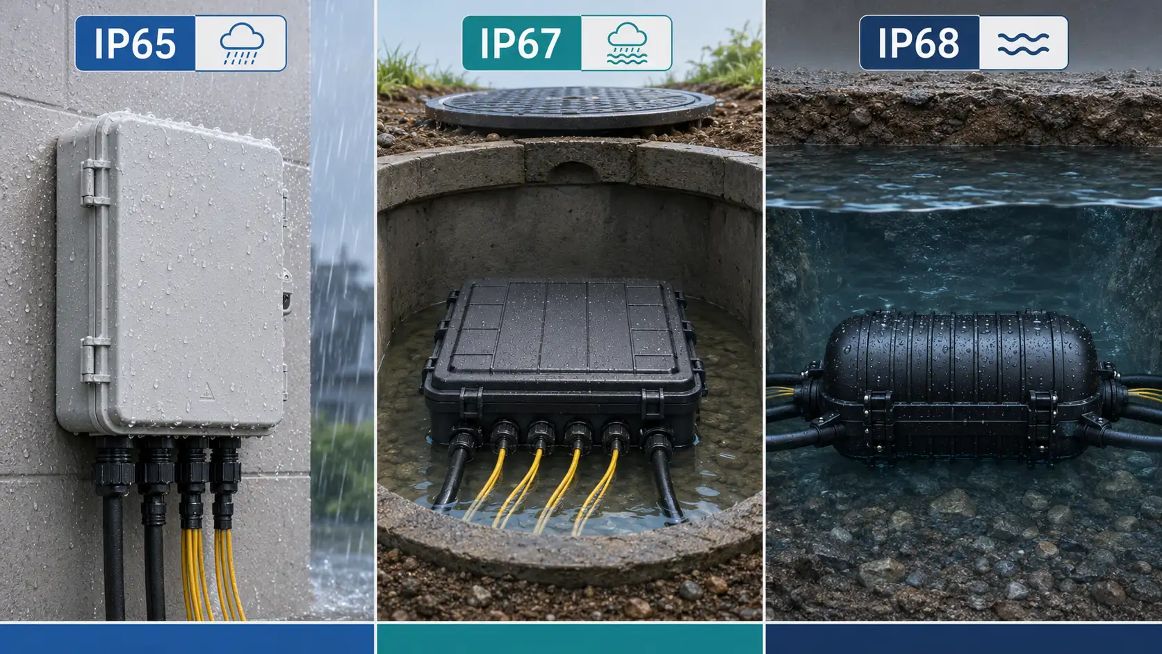
| Washdown, coolant, or oil exposure | IP67-rated connectors and an oil-resistant jacket | Corrosion and moisture ingress, often surfacing months later |
| Tight cable trays or sharp bends | Confirm minimum bend radius against the data sheet | Jacket stress and accelerated degradation |
Anonymized field example. A Tier 1 automotive supplier commissioning a robotic welding cell reported that a controller would not hold a stable link. The sequence that resolved it was straightforward: a wire-map and link-quality test on the installed runs revealed that commercial-grade, unshielded cable had been used where the controller and the EMI environment called for a shielded, correctly matched cable. Re-pulling the affected drops with the right specification fixed the problem - but only after the trays had already been closed, which turned a small specification check into a costly schedule hit. The practical lesson: confirm cable type, shielding, and jacket against the controller manual before the trays are sealed. On a high-throughput line, an hour of unplanned downtime can dwarf the price of the cable many times over, which is exactly why the specification deserves more attention than the unit cost.
FAQ
Q: Do I need a crossover cable with modern switches?
A: In almost all cases, no. Modern switches and network cards support Auto-MDIX and will adjust automatically, so a straight-through cable works even between two switches. You would only need a crossover if a port lacks Auto-MDIX or has auto-negotiation turned off.
Q: Can I use a crossover cable as a normal Ethernet cable?
A: On equipment with Auto-MDIX, yes - the port adapts to either cable type, so a crossover will usually work in place of a straight-through. On older gear without Auto-MDIX it may not. For consistency and easier troubleshooting, most installations standardize on straight-through cables and keep crossovers clearly labeled.
Q: How do I test a crossover cable?
A: Use a wire-map tester. It should show pins 1 and 2 mapping to pins 3 and 6 (the crossover pattern) and confirm there are no opens, shorts, or split pairs. Visual inspection of the connectors can confirm the color swap but will not catch termination defects.
Q: What is the difference between T568A and T568B?
A: They are two RJ45 color codes under ANSI/TIA-568. The only difference is that the green and orange pairs are swapped. Either works for a straight-through cable as long as both ends match; using one code on each end is what creates a crossover.
Q: Can crossover cables be used with EtherCAT or PROFINET?
A: Both run over standard RJ45 Ethernet wiring at the physical layer, so the connector and pinout are the same. Whether you need a crossover depends on the specific device ports and whether they support Auto-MDIX - most modern industrial devices auto-sense, but you should confirm against the device manual.
Q: What about minimum order quantities and lead time for industrial-rated cables?
A: These depend on the configuration and current stock. For standard configurations, a quote is usually quick once the four key specifications - temperature rating, shielding, connector IP rating, and bend radius - are confirmed. Custom or compliance-documented assemblies typically need more lead time; confirm the exact requirements with your supplier.
Standards and References Used in This Guide
- Fluke Networks - Differences between wiring codes T568A vs T568B (RJ45 color codes under ANSI/TIA-568).
- IEEE 802.3 working-group documentation - 1000BASE-T Automatic Crossover (MDI/MDI-X) Algorithm (basis for Auto-MDIX in Gigabit Ethernet).
- PROFIBUS & PROFINET International (PI) - PROFINET Installation Guidelines (industrial cabling, EMI separation, and bend radius).
About this guide: Written by the FOCC engineering team, which supports copper and fiber cabling for telecom, data center, and industrial automation projects. The technical points above are drawn from published standards and field experience; for specifications tied to a particular controller or environment, always verify against the manufacturer's documentation.
For crossover and Ethernet cables rated for industrial deployment, or help confirming the right specification for your environment, contact the FOCC engineering team.