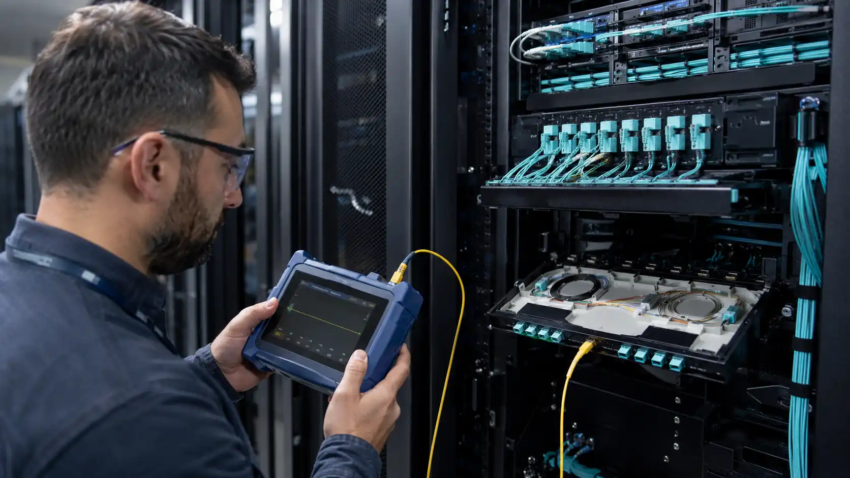
A copper SFP and a fiber SFP may fit into a similar switch cage, but they solve different physical-layer problems. A copper module presents an RJ45 interface for balanced twisted-pair Ethernet. A fiber module converts the host signal to light and connects to multimode or single-mode cabling.
The practical choice is wider than copper versus fiber. A network designer may need to choose among a native RJ45 port, a copper SFP, a direct-attach cable, an active optical cable, or a removable optical transceiver. Distance matters, but so do port speed, host support, module power, airflow, electrical isolation, diagnostics, installed cabling, PoE requirements, testing, and future migration.
Readers who need the basic form-factor background can first review what an SFP module does and the differences in SFP vs SFP+ compatibility.

Quick Answer
- Use a native RJ45 port when the switch already provides the required BASE-T speed, port density, and PoE capability.
- Use a copper SFP when an SFP-family port must connect to an RJ45 endpoint over a supported short copper channel.
- Use DAC for a supported short SFP-to-SFP equipment connection where structured RJ45 or LC patching is not required.
- Use AOC for a fixed SFP-to-SFP optical assembly when the route exceeds practical DAC length but still remains an equipment-room connection.
- Use a fiber SFP for longer links, building-to-building routes, high-EMI environments, electrical isolation, optical monitoring, or a scalable fiber backbone.
A higher-speed copper module is not simply a faster version of a 1G SFP. A 1000BASE-T SFP and a 10GBASE-T SFP+ can have different cable, reach, power, heat, negotiation, and host-platform restrictions.
Understand the Five Connection Options
Native RJ45 Port
A native BASE-T port is built directly into the switch, server, firewall, or network adapter. It is normally the cleanest choice when the device already provides the required copper interface. Native ports are also the normal starting point when many RJ45 endpoints or PoE-powered devices must be supported.
Copper RJ45 SFP
A copper SFP is a removable transceiver with an RJ45 socket. It converts the SFP host interface to a BASE-T electrical interface and uses a separate twisted-pair cable. It is most useful as a media adapter when the switch has an available SFP-family port but the remote endpoint has only RJ45.
FOCC's network cable options include common balanced copper categories. The installed channel, not only the final patch cord, must meet the speed and distance requirement.
Direct-Attach Copper Cable
A DAC is a fixed cable assembly with SFP+ or another pluggable connector on each end. It normally uses Twinax conductors and does not expose an RJ45 socket. It connects compatible SFP-family ports directly and is typically used within a rack or between nearby devices.
A DAC cannot connect directly to a server or appliance that has only an embedded RJ45 port. FOCC's introduction to direct-attach copper cables provides additional product and application background.
Active Optical Cable
An AOC is also a fixed assembly, but it carries the signal through optical fiber between integrated pluggable ends. It can extend beyond common passive-DAC lengths without requiring separate removable optical modules and patch cords.
An AOC is not a substitute for an RJ45 connection. It must be supported at both SFP-family endpoints. FOCC explains the format in its guide to active optical cable.
Fiber SFP or SFP+
A removable optical module connects to multimode or single-mode fiber, commonly through duplex LC interfaces. The local and remote modules must match in line rate, optical standard, wavelength, fiber type, connector, polarity, power budget, and host compatibility.
Available fiber optic transceivers include 1G SFP, 10G SFP+, BiDi, CWDM, DWDM, and higher-speed pluggable families.
1G Copper and Fiber SFPs
A 1000BASE-T SFP is designed for Gigabit Ethernet over four-pair copper cabling. Cisco's current 1000BASE-T SFP data sheet states that its module operates over Category 5 unshielded twisted-pair cabling up to 100 meters and supports 10/100/1000 auto-negotiation on supported platforms.
The phrase "on supported platforms" is important. A module may advertise several negotiated rates while a particular switch supports only some of them.
Common 1G optical alternatives include:
- 1000BASE-SX SFP for qualified multimode fiber.
- 1000BASE-LX/LH SFP for single-mode links and other approved applications.
At 1G, copper is often practical for a verified office or equipment-room channel inside the normal BASE-T range. Fiber becomes the better medium when the route is longer, electrically exposed, between buildings, or already served by a suitable optical cable plant.
10G Copper and Fiber SFP+ Modules
Do not apply the 100-meter 1G copper-SFP expectation to every 10G copper SFP+.
Cisco's SFP-10G-T-X is a specific reference example. Cisco documents 100M, 1G, and 10G operation on supported platforms, a 10G reach of up to 30 meters, and a maximum module power of 2.5W. At 10G, Cisco specifies Cat6A or Cat7 cabling for this module.
By comparison, IEEE 802.3an defines 10GBASE-T for up to 100 meters of balanced twisted-pair structured cabling. A native 10GBASE-T switch or adapter designed for that standard can therefore support a different channel model from a short-reach 10G copper SFP+ module. The SFP+ module's own data sheet remains the controlling limit.
Common optical alternatives include:
- 10GBASE-SR SFP+ for a qualified multimode channel.
- 10GBASE-LR SFP+ for a qualified single-mode route.
For broader fiber-media planning, compare single-mode and multimode fiber by distance, bandwidth, installed plant, and migration requirements.

Native RJ45 vs Copper SFP vs DAC/AOC vs Fiber SFP
| Decision factor | Native RJ45 | Copper SFP | DAC or AOC | Fiber SFP |
|---|---|---|---|---|
| Endpoint interface | RJ45 at both ends | SFP-family port to RJ45 endpoint | SFP-family port at both ends | Optical module at both ends |
| Cable system | Structured twisted-pair copper | Separate twisted-pair patch or channel cable | Fixed cable assembly | Multimode or single-mode fiber plant |
| Typical role | Dense copper access, native BASE-T, PoE-capable platforms | One or a few RJ45 conversions on modular ports | Short equipment-to-equipment connection | Longer, isolated, high-EMI, or scalable optical links |
| Reach | Depends on the native standard and cable | Module-specific; 1G and 10G can differ substantially | Assembly-specific | Ranges from short multimode to long single-mode applications |
| Power and heat | Managed by the native port design | Can be significant at 10G and may restrict density | Depends on passive DAC, active DAC, or AOC design | Depends on module type; check the exact data sheet |
| EMI and electrical path | Conductive copper path | Conductive copper path | DAC is conductive; AOC uses optical fiber | Non-conductive optical medium |
| Diagnostics | Link state, negotiation, counters, and platform features | Link state and device-specific module data | Assembly and host-specific data | Often includes optical DOM where supported |
| PoE | Available only on a PoE-capable native platform | Never assume; requires explicit module and host support | Not an RJ45 PoE delivery method | Not delivered through the optical fiber |
| Best selection signal | The device already provides the required copper interface | An SFP port must reach a short RJ45 endpoint | Both devices have compatible pluggable ports and are close together | The route or operating environment favors optical transmission |
When a Copper SFP Is the Better Choice
An SFP Port Must Connect to an RJ45 Device
This is the clearest use case. A switch may have spare SFP uplinks while a firewall, server, appliance, or legacy access switch presents only an RJ45 port. A supported copper SFP can create the BASE-T interface without adding an external media converter.
The Existing Copper Channel Is Verified
Reusing installed copper can be reasonable when the complete channel has passed the appropriate test and falls within the module's rate and distance limit. For a 10G copper SFP+ example that requires Cat6A, an appropriate Cat6A network cable is only one part of the channel; connectors, patch panels, workmanship, and total length also matter.
The Conversion Is Limited in Scale
One or two high-power copper modules can be acceptable in a switch that explicitly supports them. A dense bank of such modules may exceed the platform's thermal or power design. Copper SFPs are therefore often better as targeted media adapters than as a replacement for a switch built with many native RJ45 ports.
When Fiber Is the Better Choice
The Link Exceeds the Copper Module Limit
Once the route exceeds the approved copper-module channel, extending the cable is not a valid workaround. Use the optical standard that matches the installed multimode or single-mode plant and the required reach.
The Route Connects Separate Buildings
Fiber removes the metallic data path between buildings. It does not replace proper grounding, surge protection, equipment design, or local electrical requirements, but it provides electrical isolation between the network endpoints.
The Environment Has Strong EMI
Motors, variable-frequency drives, welding systems, high-voltage equipment, rail power, and industrial controls can complicate copper installation. Correctly designed copper cabling can still operate in demanding environments, but optical fiber is not affected by electromagnetic interference in the same way.
Port Density and Future Migration Matter
A qualified fiber plant can often support several equipment generations by changing the endpoint optics, provided the fiber type, connector system, channel condition, and future standard remain compatible. This is not unlimited future-proofing, but it can provide a broader migration path than a short-reach RJ45 transceiver.
Check Power, Heat, and Port Density Before Installing 10G Copper SFP+

- Identify the exact switch, line card, port group, and software release.
- Find the platform's supported-transceiver table.
- Confirm the module's maximum power rather than using a category assumption.
- Check whether adjacent-port, airflow, or inlet-temperature restrictions apply.
- Determine how many high-power copper modules the chassis permits.
- Compare the design with native RJ45, DAC, AOC, SR, or LR alternatives.
- Verify temperature and error counters during acceptance under representative traffic.
Cisco's official 10GBASE-T SFP+ guidance shows why this step matters: its cited module can consume up to 2.5W, and supported deployment density varies by platform.
Illustrative Brownfield Decision
Consider an office migration with the following requirements:
- A new aggregation switch has spare 1G SFP ports.
- A remote firewall has only a 1000BASE-T RJ45 interface.
- The existing horizontal channel is approximately 70 meters.
- The copper channel has passed the required wire-map and performance test.
- No PoE is required.
- The switch compatibility table lists the selected 1000BASE-T SFP.
In this situation, a supported copper SFP is a reasonable choice. The endpoint is already RJ45, the route is inside the cited 100-meter 1G class, and the existing copper channel can be reused.
The same answer would change if the link were 300 meters, connected separate buildings, passed through a high-EMI industrial area, or required a future 10G backbone. Those conditions would shift the design toward an appropriate optical module and fiber plant.
This is an illustrative decision framework, not a record of an installed customer project.
Compatibility, Multi-Rate Operation, and PoE
Physical fit does not prove support. Confirm the exact port type, line rate, module coding, software release, remote endpoint, negotiation behavior, cable system, power, temperature, and port-group restrictions.
Cisco's current compatibility resources allow users to search supported optics by hardware and transceiver. Similar vendor tools should be used for other platforms.
Do not infer 2.5G or 5G support from a module that advertises 100M, 1G, and 10G. Multi-gigabit operation must be explicitly documented by the module and host.
Do not assume that a standard data-oriented copper SFP supplies Power over Ethernet. PoE requires a power-sourcing design that is explicitly supported by the module and host. When PoE and dense RJ45 access are primary requirements, a native PoE switch port is normally the clearer architecture.
Diagnostics and Acceptance Evidence
Optical modules commonly expose Digital Optical Monitoring through the SFF-8472 management interface. Where supported, fields can include Tx optical power, Rx optical power, module temperature, supply voltage, laser bias current, and alarm thresholds.

A copper module has no optical Tx or Rx power to report. It may still expose temperature, voltage, identification, or vendor-specific information, depending on the module and host. Avoid the blanket statement that every copper SFP has no diagnostics.
| Evidence | Native RJ45 or Copper SFP | DAC or AOC | Fiber SFP |
|---|---|---|---|
| Inventory | Port, module part number, negotiated rate | Cable assembly part number and supported length | Local and remote module part numbers |
| Medium verification | Cable category, wire map, channel length | Assembly type and endpoint compatibility | Fiber type, wavelength, connector, polarity |
| Physical test | Certification or qualification where required | Host recognition and link stability | Insertion loss and connector inspection |
| Diagnostics | Negotiation, counters, link flaps, available module data | Host and assembly-specific information | DOM Tx/Rx, temperature, voltage, bias, thresholds |
| Operational test | Errors and representative traffic | Errors and representative traffic | Errors and representative traffic |
| Additional location evidence | Copper fault-distance tools where appropriate | Normally limited by fixed assembly design | OTDR where route-event evidence is required |
FOCC's guide to testing an Ethernet cable explains common copper checks. For optical channels, use fiber optic power-meter testing to verify end-to-end loss under an approved test plan.
Compare Total Cost, Not Only Module Price
| Cost area | Questions to include |
|---|---|
| Interfaces | Are native ports already available, or are modules and adapters required? |
| Cabling | Can the existing channel be reused, and has it passed the correct test? |
| Patching | Are RJ45 panels, LC panels, cassettes, or fixed assemblies required? |
| Power and cooling | Does the option increase module power, heat, or port-density restrictions? |
| Installation skills | Does the project require copper certification, fiber cleaning, splicing, or optical testing? |
| Operations | What diagnostics, spares, cleaning tools, and fault-location methods are required? |
| Migration | Will the installed medium support the planned next rate and architecture? |
| Downtime risk | Is the option approved by both endpoint vendors, and is a rollback path available? |
For data-center-specific comparisons among copper, DAC, multimode, and single-mode options, review FOCC's 10GbE cabling options.
Common Selection Mistakes
| Mistake | Why it fails | Better approach |
|---|---|---|
| Treating every copper SFP as a 100-meter module | 1G and 10G products can have different channel and power limits | Use the exact part-number data sheet |
| Using a copper SFP when a suitable native RJ45 port is free | It consumes a modular port and may add heat or compatibility restrictions | Use the native interface unless a clear design constraint justifies the module |
| Confusing RJ45 copper SFP with DAC | The connector, cable, PHY, and remote endpoint differ | Identify the physical interface at both ends before ordering |
| Filling a switch with high-power 10G copper modules | The chassis may not support the required power or airflow | Check vendor deployment limits and compare native copper or optical alternatives |
| Assuming a standard copper SFP supplies PoE | Data connectivity does not prove power-sourcing capability | Require explicit module and host PoE support |
| Choosing fiber only because it is "more secure" | Network security depends on access control, configuration, monitoring, and physical protection | Choose the medium based on distance, isolation, EMI, operations, and risk |
| Expecting optical Tx/Rx readings from a copper module | The copper PHY does not have an optical signal path | Use available module data, negotiation state, counters, and copper tests |
| Accepting a link because it is up | Link state does not prove channel compliance or stability under load | Complete the appropriate physical and traffic acceptance tests |
FAQ
Q: Can an RJ45 cable plug directly into an empty SFP port?
A: No. An RJ45 plug requires a supported copper SFP or a native RJ45 port. The empty cage does not contain a BASE-T interface.
Q: How far can a copper SFP transmit?
A: It depends on rate, module, host, cable, and channel. Cisco's cited 1000BASE-T SFP supports up to 100 meters, while its cited 10GBASE-T SFP+ supports 10G up to 30 meters.
Q: Is fiber always faster than copper?
A: No. Speed is set by the Ethernet interface. A 1G copper SFP and a 1G optical SFP both carry Gigabit Ethernet. The medium changes reach, electrical behavior, power, diagnostics, and migration options.
Q: Can a copper SFP connect directly to a fiber SFP?
A: No. BASE-T electrical signaling and an optical Ethernet interface require a switch, media converter, or another device that terminates and converts the two media.
Q: Does a copper SFP support PoE?
A: Do not assume it does. PoE must be explicitly supported by the module and host. Standard data connectivity alone does not create a PoE power-sourcing port.
Final Decision Checklist
- Identify both endpoint interfaces before choosing the medium.
- Confirm whether a suitable native RJ45 port is already available.
- Separate 1G copper-SFP limits from 10G copper-SFP+ limits.
- Confirm switch, line card, port group, and software support.
- Verify copper cable category and the complete channel length.
- Verify optical standard, wavelength, fiber type, connector, and polarity.
- Check module power, airflow, temperature, and permitted port density.
- Use DAC or AOC only when both endpoints support the fixed assembly.
- Do not infer PoE, 2.5G, or 5G support without documentation.
- Complete the correct physical-layer and traffic acceptance tests.
- Compare total cost, operating effort, and future migration rather than module price alone.
- Keep an approved rollback interface available until the new link is accepted.
The best choice is not copper or fiber in isolation. It is the supported combination of port, module, cable, distance, power, operating environment, diagnostics, and test evidence that meets the actual link requirement.