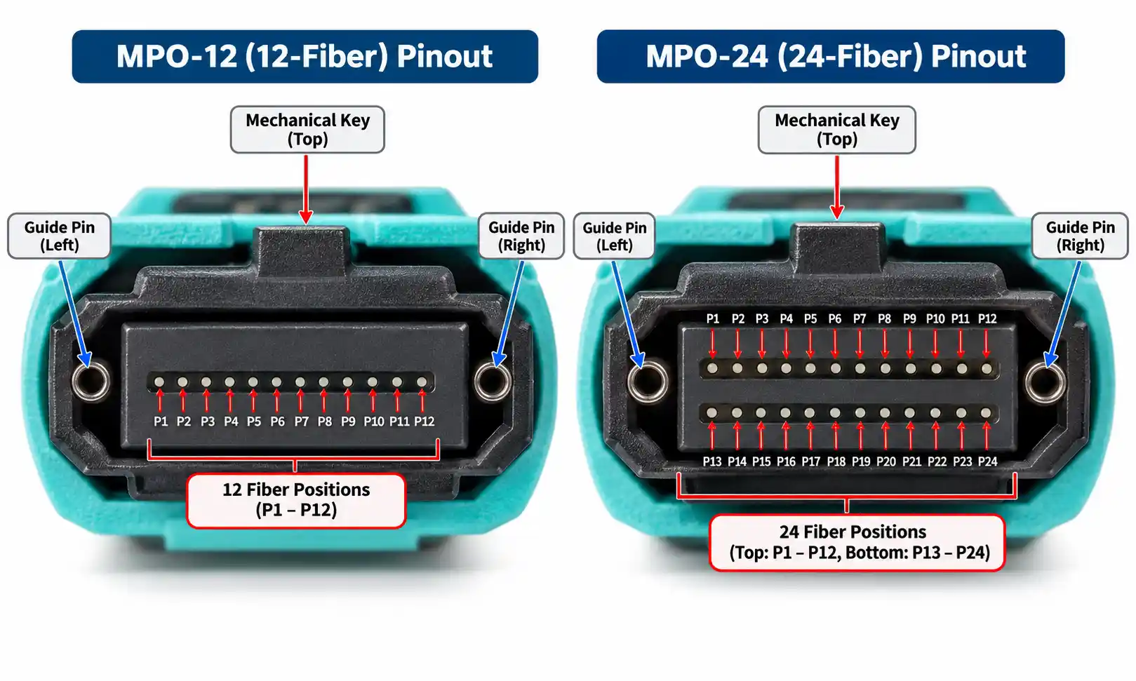
An MPO fan-out cable is a pre-terminated fiber assembly that takes multiple fibers from one MPO interface and distributes them into individual connectorized branches, typically LC or SC. It is useful when a high-density MPO-based link must transition to equipment ports, patching points, test interfaces, or other components that use individual fibers or duplex pairs.
The connector count alone does not define compatibility. Two assemblies that both look like "MPO to 6 duplex LC" can differ in fiber count, pinned or unpinned MPO interfaces, polarity, fiber-to-branch mapping, fiber type, connector polish, loss requirements, and branch construction. The practical goal is therefore not to buy a cable that merely fits; it is to specify a cable whose mechanical interface and optical map match the complete channel.
If you are comparing available assemblies, start with the site's MPO/MTP fan-out cable range, then verify the exact drawing and test requirements against the equipment at both ends.
What Is an MPO Fan-Out Cable?
A typical assembly has five physical sections:
MPO connector → main cable → breakout transition → fan-out legs → LC, SC, or other branch connectors

The MPO end is the multi-fiber interface. The fan-out transition separates the fibers into manageable legs, and each branch terminates the fiber or fiber pair needed by the downstream port. The assembly does not convert protocols, change wavelengths, or create additional optical lanes; it implements a physical fiber map.
MPO is a standardized connector family. IEC publishes interface standards for one-row MPO connectors in IEC 61754-7-1 and two-row MPO connectors in IEC 61754-7-2. These standards define connector interface dimensions; they do not tell you which fiber map your specific network should use.
MPO Fan-Out vs Breakout vs Harness Cable
Suppliers do not always use fan-out, breakout, and harness in exactly the same way. In procurement, the terms often overlap more than the product drawings do.
| Term | Typical Meaning | What Actually Needs Verification |
|---|---|---|
| MPO fan-out cable | One MPO interface separated into multiple connectorized branches | Fiber count, branch layout, connector type, polarity and mapping |
| MPO breakout cable | Often an MPO assembly that breaks a multi-fiber interface into individual channels or ports | Whether the active equipment supports the intended breakout architecture |
| MPO harness cable | Usually emphasizes a ready-to-install multi-branch assembly | Exact connector and branch configuration |
If a project specification uses the word "harness," compare it with the actual MPO/MTP harness cable configurations rather than assuming the name alone describes polarity or lane assignments.
MPO vs MTP: What Is the Difference?
MPO is the connector format. MTP® is US Conec's branded MPO connector family. US Conec's official MTP/MPO FAQ states that an MTP connector is an MPO connector and is designed to comply with the cited MPO interface standards.
For buying purposes, "MTP" or "MPO" still does not complete the specification. You must identify the mating interface, pin configuration, fiber count, fiber type, polarity or approved map, performance requirements, and the components on both sides of the channel.
How an MPO Fan-Out Cable Works: Fiber Mapping and Polarity
Fiber Mapping
Inside the MPO connector, each fiber occupies a defined position. The cable routes those positions to branch connectors. A production drawing should therefore make the mapping explicit rather than leaving installers to infer it from branch count.
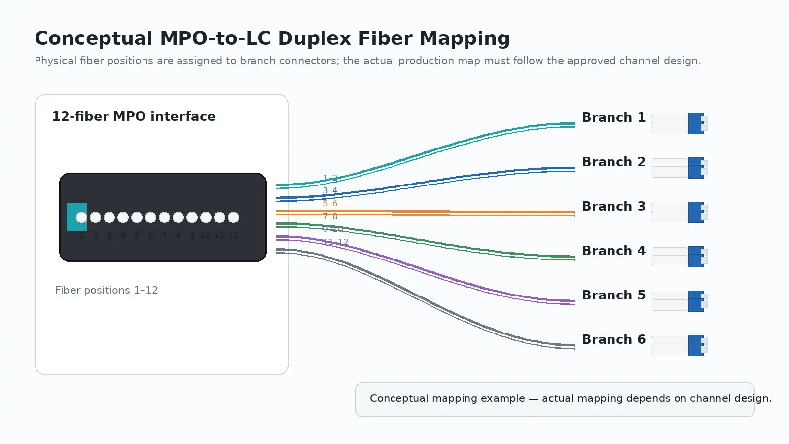
For an MPO-to-LC duplex assembly, a useful mapping sheet should identify:
- every MPO fiber position used by the assembly;
- the LC branch number associated with each fiber or pair;
- the A-side and B-side fiber within each duplex pair where applicable;
- MPO key orientation and pinned or unpinned interface information;
- branch labels that match the drawing and packaging.
A conceptual example might show "MPO positions → LC branch 1, branch 2, branch 3…" but the exact position-to-branch sequence is not universal. It must match the approved channel architecture.
Why Polarity Is a Channel-Level Requirement
In a duplex optical link, a transmitter must ultimately reach the intended receiver. In an MPO-based system that path may pass through trunks, adapters, cassettes, fan-out cables and duplex patch cords. A cable can mate mechanically at both ends and still produce no link if the end-to-end Tx/Rx path is wrong.
When project documents specify Type A, Type B, Type C or another defined polarity arrangement, treat that as part of the end-to-end cabling design rather than as a label to copy from an unrelated assembly. TIA's current optical fiber cabling component standard is ANSI/TIA-568.3-E; project drawings and equipment documentation should determine how that design is implemented in the actual channel.
Failure Scenario: Everything Fits but the Link Stays Down
Consider two 12-fiber MPO-to-six-duplex-LC assemblies with identical lengths and connector counts. If one assembly follows the approved fiber map and the other assigns one or more Tx fibers to the wrong LC-side receivers, both cables may plug in normally, but only one will establish the intended optical paths. This is why a signed mapping drawing is more useful than a short description such as "12F MPO to 6×LC duplex."
Types of MPO Fan-Out Cables
"Types" becomes clearer when the assembly is classified by one design variable at a time.
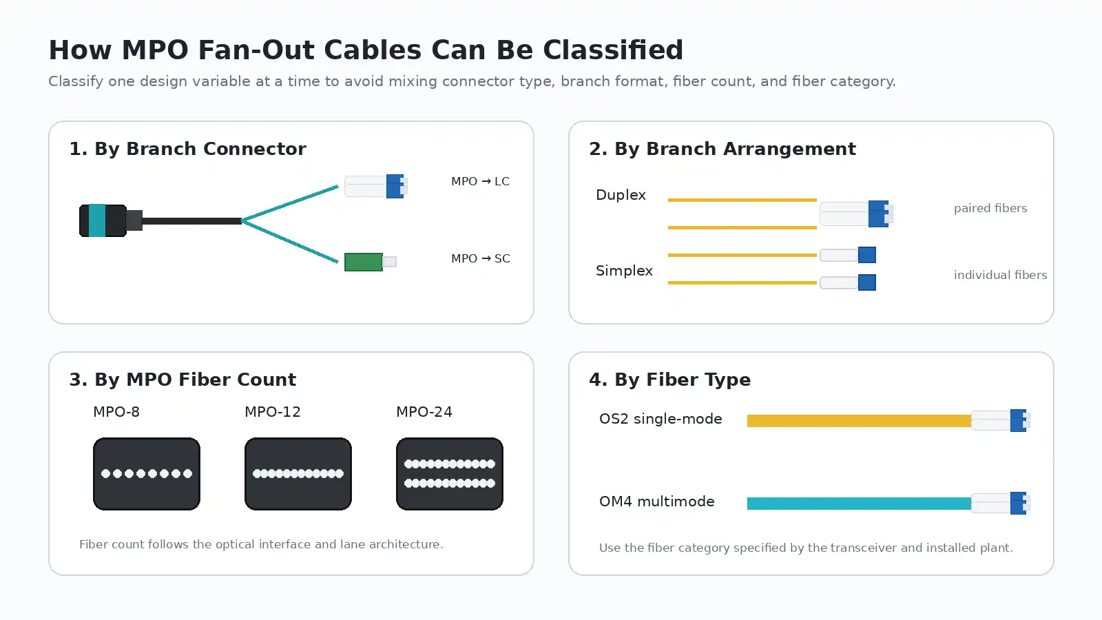
1. By Branch Connector
MPO to LC is common where the fan-out must reach compact duplex or simplex LC equipment interfaces. MPO to SC and other connector combinations may be appropriate for distribution frames, telecom rooms, test systems or existing infrastructure.
2. By Branch Arrangement
Duplex branches keep two fibers together as a pair and are convenient where equipment ports are managed in Tx/Rx pairs. Simplex branches expose individual fibers separately, which may be preferred for testing, lab access, non-duplex applications or specific labeling schemes.
3. By MPO Fiber Count
Common project formats include MPO-8, MPO-12 and MPO-24, but fiber count should follow the optical interface and lane architecture rather than a generic "speed-to-fiber-count" rule. IEC's MPO family also includes one-row and multi-row connector interfaces, so the mating hardware must be specified rather than inferred from the word MPO alone.
4. By Fiber Type
Fan-out assemblies may be built with single-mode or multimode fiber. If the existing channel is single-mode, an OS2 single-mode cabling family is the relevant reference point. For many short-reach data-center multimode designs, OM4 multimode cabling is a common option, but the transceiver specification and installed plant should decide the grade.
Where MPO Fan-Out Cables Are Used
Equipment-Side Distribution
A high-density MPO backbone or patching system may need to terminate at equipment that presents multiple LC ports. A fan-out assembly can make that transition directly without adding a separate cassette at the equipment end.
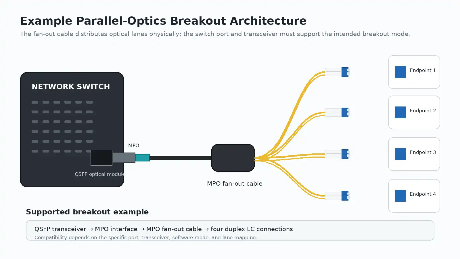
Parallel-Optics Breakout
Some optical modules can operate in a breakout mode, but the cable does not create that capability. The port, transceiver, software configuration and optical lane mapping all have to support it.
A useful real-world example is Cisco's 40GBASE-SR4 family. Cisco's 40GBASE QSFP module data sheet states that QSFP-40G-SR4 can be used in a 4×10G breakout mode, while QSFP-40G-SR4-S does not support 4×10G breakout connectivity. The connector form alone therefore cannot tell you whether a breakout fan-out cable will work. The site's 40G QSFP transceiver section can help identify the optical module family before the cable is specified.
Telecom, Distribution and Test Environments
Fan-out assemblies are also useful where technicians need individual access to fibers for service distribution, validation or test work. In these environments, branch labels and a readable fiber map can save more troubleshooting time than a generic product name ever will.
MPO Fan-Out Cable vs MPO Trunk vs Cassette
| Architecture | Primary Function | Best Fit |
|---|---|---|
| MPO fan-out cable | Transitions one MPO interface to multiple connectorized branches | Direct equipment-side distribution |
| MPO trunk cable | Connects MPO interfaces at both ends | High-density backbone links |
| MPO cassette | Provides a modular MPO-to-individual-connector transition in a housing | Structured patching and environments with frequent moves, adds and changes |
If the design requires an MPO backbone rather than equipment-side branches, compare MPO/MTP trunk cabling. Where serviceability and modular patching are more important than the lowest component count, an MPO/MTP cassette architecture may be easier to manage.
How to Choose an MPO Fan-Out Cable in 7 Steps
Step 1: Identify the Active Equipment Interface
Record the exact equipment port and transceiver part number before counting branch connectors. Confirm connector type, port mode, supported breakout behavior and the number of optical lanes actually used.
Step 2: Define MPO Fiber Count and Lane Mapping
Translate the equipment lane requirement into the MPO-side fiber positions and branch assignments. For a custom assembly, request or approve a fiber map before production.
Step 3: Select the Fiber Type
Match the cable to the transceiver wavelength, link design and installed cabling. Do not treat OM3, OM4, OM5 or OS2 as a simple quality ranking; they serve different optical designs.
Step 4: Confirm the MPO Interface and Pin Configuration
Verify what the cable will mate with: equipment receptacle, adapter, cassette, trunk or another assembly. Confirm pinned versus unpinned requirements and connector orientation on the drawing.
Step 5: Approve Polarity and Fiber-to-Branch Mapping
This is the point where a drawing is more valuable than a catalog description. Check branch numbering, duplex pair assignments and end-to-end Tx/Rx continuity against the project architecture.
Step 6: Specify Cable and Fan-Out Construction
Define total length, fan-out leg length, equal or staggered branches, branch diameter, jacket requirement, bend constraints, routing path and strain relief. A cable can be optically correct and still be awkward to install if the branch geometry does not match the rack layout.
Step 7: Define Test and Acceptance Requirements
Specify any required insertion-loss limits, test report format, branch labeling, mapping documentation and inspection criteria before the order is released. Repeat projects benefit from using the same acceptance format each time.
Common Buying Mistakes
- Buying by connector count: the expected number of LC connectors does not prove that polarity, fiber type or mapping is correct.
- Copying a previous cable's pin configuration: the mating interface may be different even when the cable looks similar.
- Assuming breakout is automatic: active equipment must support the intended breakout mode.
- Ignoring fan-out leg length: correct total length does not guarantee clean routing at the ports.
- Ordering without a mapping sheet: multi-branch assemblies become harder to install, test and reorder when branch identity is undocumented.
- Leaving test criteria undefined: suppliers cannot reproduce an acceptance process that was never specified.
Installation, Inspection and Maintenance
Inspect Connector End Faces Before Mating
Multi-fiber connectors are sensitive to contamination across a relatively large ferrule surface. IEC 61300-3-35:2022 defines procedures and criteria for visual inspection of fiber-optic connector and transceiver end faces and notes that visual inspection complements, rather than replaces, optical performance measurements.
Protect the Fan-Out Transition and Branches
Avoid excessive pulling, crushing, sharp bends and strain at the breakout transition. Route branch legs so that port access does not force the fibers into tight bends or place tension on the connector boots.
Keep Labels Consistent With the Mapping Sheet
Branch labels should remain visible after installation and should match rack, panel and port documentation. If the cable is replaced later, that documentation becomes the reference for reproducing the assembly correctly.
FAQ About MPO Fan-Out Cables
Is an MPO fan-out cable the same as an MPO breakout cable?
Often the terms overlap, but they are not reliable specifications by themselves. Compare the actual connector interfaces, fiber count, branch arrangement, mapping and intended application.
Is MTP the same as MPO?
MTP® is a branded MPO connector family from US Conec. It belongs to the MPO format, but a procurement specification should still define the exact connector interface and performance requirements.
Can an MPO fan-out cable connect directly to a transceiver?
Yes, when the transceiver receptacle, pin configuration, fiber count, polarity and optical lane mapping are designed for that direct connection. A physical fit does not prove optical compatibility.
How do I choose between MPO-8, MPO-12 and MPO-24?
Start with the active optical interface and lane architecture. Select the fiber count that supports the equipment and channel design instead of choosing a format simply because it is commonly stocked.
What MPO polarity should I use?
Use the polarity method defined by the complete channel design. If no project standard is already established, approve an end-to-end fiber map before ordering rather than selecting Type A, B or C in isolation.
Should I request an insertion-loss test report?
If the project has optical acceptance limits, repeatability requirements or custom mappings, define the test criteria and report format in the purchase specification. A report is only useful when the measurement method and acceptance limit are clear.
Conclusion
An MPO fan-out cable is best specified as part of an optical channel, not as a standalone patch cord. The decisive details are the equipment interface, fiber count, MPO pin configuration, fiber type, polarity, fiber-to-branch mapping, physical branch design and acceptance criteria.
Once those details are documented, comparing suppliers becomes much easier: you are no longer asking whether two cables have the same name or connector count, but whether they implement the same approved optical and mechanical design.