MTP to LC breakout cables bridge high-density multi-fiber backbone systems with traditional duplex equipment connections. These cables convert a single 8-, 12-, or 24-fiber MTP connector into multiple LC duplex connectors, enabling efficient transitions between different network speeds and equipment types.

Network Migration Scenarios
10G to 40G Network Transitions
When upgrading from 10 gigabit to 40 gigabit infrastructure, MTP to LC breakout cables provide a cost-effective migration path without replacing existing equipment. An 8-fiber MTP to LC configuration connects one 40GBASE-SR4 QSFP+ transceiver to four 10GBASE-SR SFP+ transceivers, utilizing all fiber strands efficiently.
This deployment model became widespread in data centers between 2017-2024, as organizations needed to support both legacy 10G servers and new 40G switches simultaneously. The breakout approach eliminates the need for complete infrastructure replacement, reducing capital expenditure by 60-75% compared to full-system upgrades.
The technical implementation relies on parallel optics, where the 40G signal splits into four independent 10G lanes. Each lane operates at 10 Gbps over multimode fiber (OM3 or OM4), achieving transmission distances up to 100-150 meters depending on fiber grade. This distance suffices for most intra-datacenter connections while maintaining signal integrity across all channels.
25G to 100G Migration Paths
Similar principles apply when transitioning from 25G to 100G networks using MTP to LC architecture. An 8-fiber MTP connection on a QSFP28 100G transceiver breaks out to four SFP28 25G transceivers through individual LC duplex connectors. This configuration supports incremental capacity expansion as application demands grow.
Network architects favor this approach when application servers require different bandwidth tiers. Storage arrays might demand full 100G throughput while compute nodes operate efficiently at 25G, and MTP to LC breakout cables accommodate both requirements within unified infrastructure.
High-Density Cabling Environments
Space Optimization in Data Centers
Data centers face constant pressure to maximize port density within limited rack space. MTP to LC breakout solutions deliver substantial space savings compared to traditional LC-to-LC cabling. A 1U fiber panel with 12 MTP rear ports and 48 LC front ports consolidates what would otherwise require 4U of conventional patch panel space.
The density advantage becomes more pronounced at scale. Using 24-fiber MTP configurations, a single 1U enclosure can manage up to 1,152 fiber strands through MTP-24 cables, representing six times the capacity of duplex LC systems. This space efficiency translates directly to reduced rack costs, improved airflow, and simplified cable management.
Real-world implementations show that high-density MTP deployments reduce cable pathway congestion by 65-80%. Fewer individual cables means easier troubleshooting, faster moves-adds-changes, and lower labor costs for ongoing maintenance. Network teams report 40-60% reduction in cable installation time when deploying MTP backbone with LC breakout versus point-to-point LC cabling.
Structured Cabling Architectures
MTP to LC breakout cables excel in structured cabling environments where permanent backbone links connect to flexible access layer equipment. The MTP side terminates into cassettes or patch panels serving as the building's permanent infrastructure, while LC breakouts provide equipment-level connectivity that changes frequently.
This architecture separates stable infrastructure (the MTP backbone) from dynamic connectivity (LC breakout legs). When replacing or relocating equipment, technicians only handle the LC connections while the high-fiber-count MTP trunk remains undisturbed. The approach reduces wear on expensive trunk cables and maintains long-term network reliability.
Equipment Compatibility Requirements
Transceiver Interface Matching
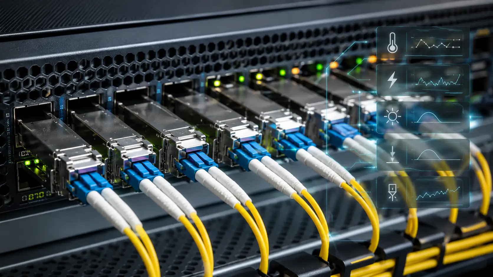
MTP to LC cables address the interface mismatch between modern parallel optics transceivers and legacy equipment. Current 40G and 100G short-reach transceivers (SR4, CSR4) feature MTP/MPO interfaces supporting 8-12 fiber parallel transmission. Meanwhile, the installed base of 10G and 25G equipment predominantly uses LC duplex connectors.
Without MTP Breakout Cable solutions, connecting these different interface types would require expensive media conversion equipment or complete transceiver replacement. The breakout cable provides direct optical connectivity, eliminating active conversion layers and their associated cost, power consumption, and failure points.
Specific transceiver compatibility matters when selecting MTP to LC configurations. For instance, 40GBASE-SR4 transceivers require 8-fiber MTP connections that break out to four LC duplex pairs. The cable must match the transceiver's polarity requirements (typically Type B for parallel optics applications) to ensure transmit lanes correctly align with receive lanes across the link.
Switch Port Breakout Capabilities
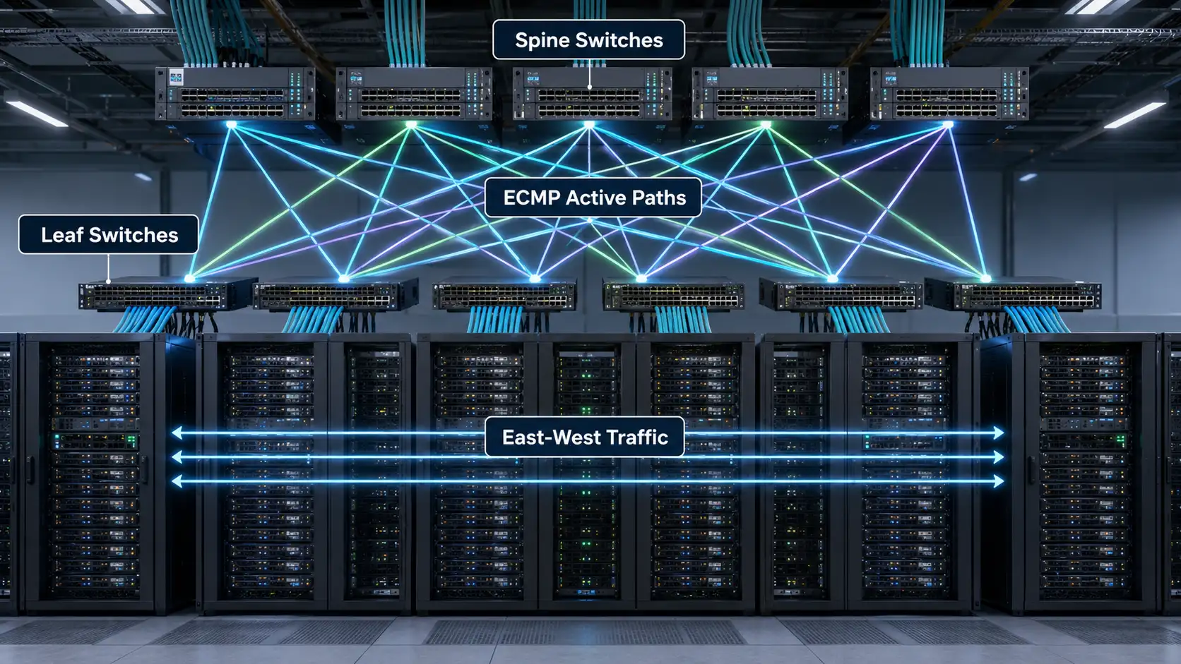
Modern data center switches from Cisco, Arista, Juniper, and others support port breakout configurations allowing a single 40G or 100G port to function as multiple lower-speed ports. When enabled through switch configuration, one 40G QSFP+ port becomes four independent 10G interfaces, or one 100G QSFP28 port splits into four 25G ports.
MTP to LC breakout cables physically enable these software-defined port splits. The MTP connector plugs into the high-speed QSFP transceiver while each LC pair connects to separate network devices, creating four independent data paths. This flexibility allows network operators to right-size bandwidth allocation to actual application needs rather than over-provisioning to match available port speeds.
Implementation requires both hardware capability (the MTP to LC cable) and software configuration. Switches must support breakout mode for specific ports, typically configurable through command-line interface or management software. Not all switch models support breakout on every port, so verifying compatibility before deployment prevents integration issues.

Fiber Type Considerations
Multimode vs. Single-Mode Deployments
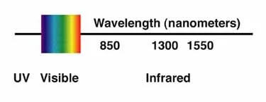
The choice between multimode and single-mode MTP to LC cables depends primarily on transmission distance requirements. Multimode configurations using OM3 or OM4 fiber suit the majority of data center applications with distances under 100-400 meters. These deployments benefit from lower-cost 850nm optics and simplified connector polishing requirements.
OM4 multimode fiber, the most common choice for MTP to LC breakout applications in 2024-2025, supports 40GBASE-SR4 up to 150 meters and 100GBASE-SR4 up to 100 meters. The next-generation OM5 fiber extends these distances slightly while adding support for shortwave wavelength division multiplexing (SWDM), though OM4 remains the dominant standard for cost-performance balance.
Single-mode MTP to LC breakout cables serve longer-distance applications exceeding multimode capabilities. Campus interconnects, metro-area connections, and inter-building links spanning several kilometers require single-mode fiber with 1310nm or 1550nm optics. However, single-mode deployments cost 2-3x more than multimode due to tighter tolerances and precision connector requirements.
Connector Polarity Management
Proper polarity management ensures transmitted signals reach the correct receive fibers throughout the MTP to LC connection. The industry standardizes three polarity methods (Type A, Type B, Type C) for different application scenarios. Type B polarity dominates 40G/100G breakout applications because it maintains consistent fiber positions from the 12-fiber MTP connector through each LC duplex pair.
Polarity errors cause complete link failure or partial channel loss, making verification essential during installation. Visual inspection of connector key positions, fiber numbering, and using proper test procedures prevents costly troubleshooting after deployment. Many organizations color-code different polarity types to prevent mixing incompatible cables within the same system.
Installation and Deployment Factors
Pre-Terminated vs. Field-Terminated Solutions
Pre-terminated MTP to LC breakout cables arrive from the factory with all connectors installed, tested, and certified. This plug-and-play approach eliminates field termination labor, reduces installation errors, and provides consistent performance backed by manufacturer warranties. Factory testing ensures insertion loss, return loss, and polarity meet specifications before the cable reaches the installation site.
The alternative-field termination-requires specialized tools, trained technicians, and time-consuming testing procedures. While field termination offers length flexibility, the skill requirements and quality variability make pre-terminated solutions preferable for most MTP to LC breakout applications. Installation time differences are substantial: pre-terminated cables take 5-15 minutes to deploy and verify, while field termination requires 2-4 hours per connector endpoint.
Cost analysis favors pre-terminated solutions for all but the smallest deployments. Though unit costs run higher than raw cable and connectors, eliminating field labor, test equipment, and potential rework from termination defects yields 30-50% total cost savings in typical projects.
Cable Management and Routing
MTP to LC breakout cables present unique cable management challenges due to their transition from a single trunk to multiple LC legs. The breakout point requires adequate space for the fanout and strain relief to prevent fiber damage. Specialized breakout boots distribute stress across the fiber bundle, protecting individual strands from excessive bending or tension.
Proper routing maintains minimum bend radius throughout the cable length. MTP to LC cables typically specify 10-15x cable diameter for loaded bends (installed and secured) and 20x diameter for unloaded installation bends. Violating these specifications causes signal attenuation, increased insertion loss, and potential fiber breaks that manifest as intermittent or permanent link failures.
Effective cable management strategies separate the MTP trunk routing from LC breakout leg management. The trunk follows high-capacity pathways to distribution points, where breakout occurs in controlled zones with adequate space. LC legs then route through standard cable management to individual equipment connections, keeping the complex fanout organized and maintainable.
Performance and Reliability Factors
Insertion Loss Budgets
Every optical connection introduces insertion loss, which must remain within link budget constraints for reliable operation. MTP to LC breakout cables add two connector interfaces per channel (one MTP and one LC), each contributing 0.35-0.75 dB typical insertion loss. Additional splices or intermediate connections further reduce available loss margin.
For 40GBASE-SR4 over OM4 fiber, the IEEE specification allows maximum 1.5 dB insertion loss. A typical MTP to LC breakout deployment consumes 0.5-1.0 dB, leaving margin for patch cords, cassettes, and fiber plant loss. Exceeding the loss budget causes bit errors, link flapping, or complete connection failure, especially at maximum specified distances.
High-quality MTP to LC cables from reputable manufacturers specify maximum 0.35 dB insertion loss per connector pair, with many achieving 0.25 dB or less. Premium "elite" or "low-loss" variants further reduce insertion loss to 0.15 dB per mated pair, valuable in long links or systems with multiple connection points where every fraction of a decibel matters.
Environmental Durability
Standard MTP to LC cables suit controlled data center environments with stable temperature and humidity. More demanding applications require specialized variants: plenum-rated cables for air-handling spaces meet fire safety codes, while outdoor-rated versions withstand temperature extremes, moisture, and UV exposure.
Armored MTP to LC breakout cables provide mechanical protection in environments with crush hazards or frequent handling. Steel or aramid fiber reinforcement increases tensile strength by 5-10x compared to standard cables, preventing damage during installation or from inadvertent contact. The additional protection comes with increased cost and reduced flexibility, appropriate where physical resilience outweighs handling convenience.
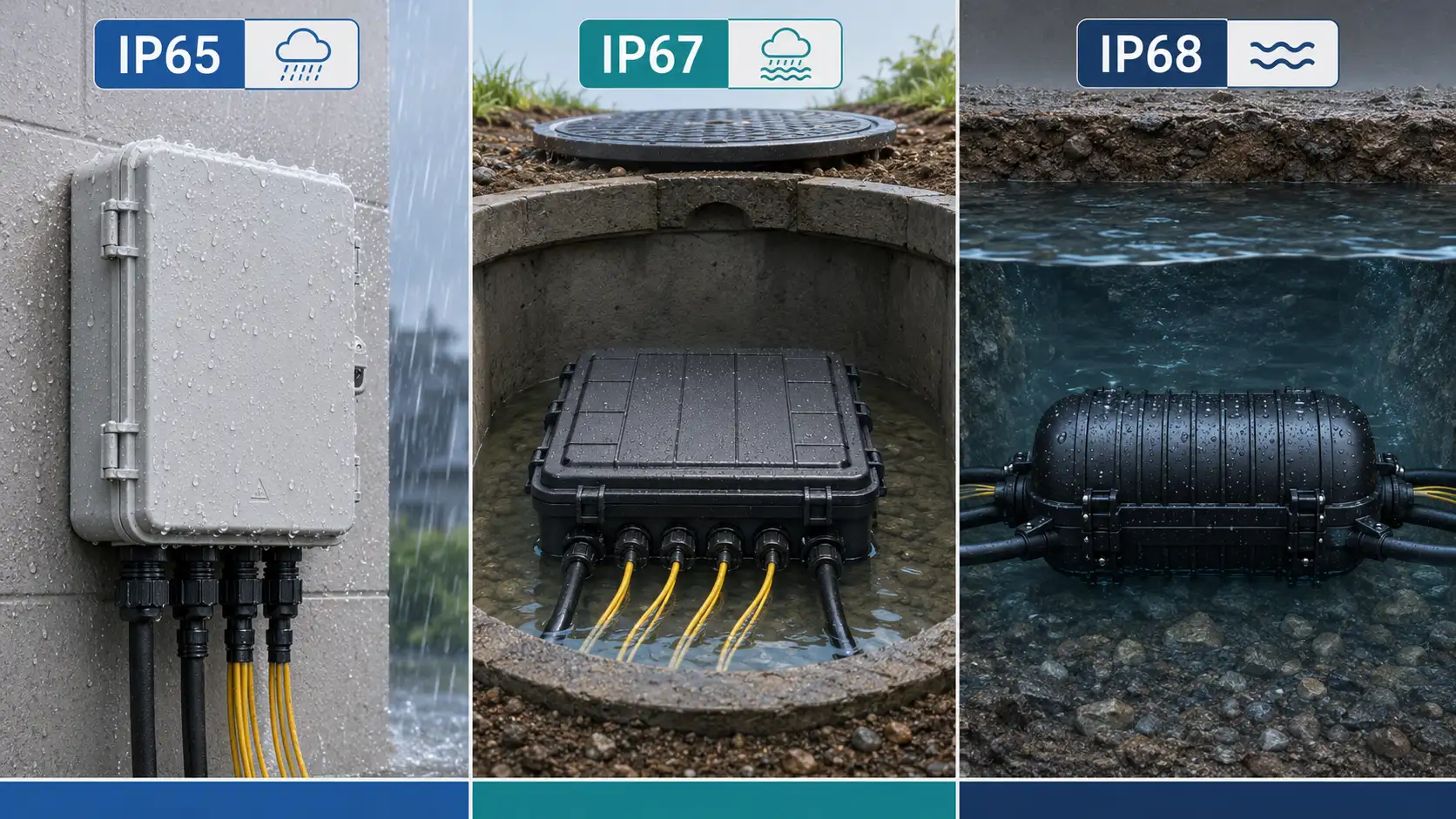
Industrial and outdoor MTP to LC deployments may specify IP68-rated weatherproof connectors that seal against water and dust ingress. These specialized variants enable fiber connectivity in telecommunications cabinets, remote antenna installations, and other harsh environments where standard connectors would fail.

Cost and Scalability Analysis
Initial Deployment Economics
MTP to LC breakout cable costs vary significantly based on fiber count, length, connector quality, and ratings. An 8-fiber OM4 plenum MTP to LC cable (3 meters) typically costs $80-$150 from major manufacturers, while equivalent 12-fiber variants range $120-$200. Single-mode versions command 30-50% premiums over multimode due to tighter manufacturing tolerances.
Comparing total cost of ownership, MTP to LC breakout solutions provide superior economics at moderate scale. For four 10G connections, using a single MTP to LC breakout cable costs approximately the same as four individual LC duplex patch cords plus associated infrastructure. However, the breakout approach saves substantial labor during installation and reconfiguration while enabling future upgrades to 40G by replacing only the transceivers.
At larger scales, cost advantages multiply. A data center requiring 48 10G connections can deploy 12 MTP to LC breakout cables instead of 48 individual LC trunks, reducing cable count by 75%, simplifying infrastructure, and cutting installation time proportionally. The consolidated approach also reduces ongoing operational costs through simplified maintenance and faster troubleshooting.
Future-Proofing Strategies
Network infrastructure typically operates 7-10 years before major upgrades, making future-proofing essential for protecting investment. MTP to LC systems excel at accommodating technology transitions because the cabling infrastructure remains stable while only transceivers change to enable new speeds.
A data center installing 8-fiber MTP backbone with LC breakout cassettes today can support multiple evolution paths: current 40G-to-4x10G, future 100G-to-4x25G, or even 400G-to-4x100G using the same physical fiber plant. This flexibility comes from the parallel optics architecture where speed increases occur by upgrading transceivers to faster per-lane data rates rather than requiring complete cable replacement.
However, true future-proofing requires selecting appropriate fiber types during initial deployment. OM4 multimode fiber installed today will support anticipated speed increases through 2030-2035 for typical data center distances. Organizations planning longer infrastructure lifecycles should consider OM5 or single-mode fiber despite higher initial costs, ensuring the passive plant accommodates next-generation technologies without premature replacement.
Frequently Asked Questions
What's the difference between an 8-fiber and 12-fiber MTP to LC breakout cable?
An 8-fiber MTP to LC configuration uses all fibers efficiently, providing exactly four duplex LC pairs from the eight total fibers. This matches 40G SR4 and 100G DR4 applications perfectly with no waste. A 12-fiber version provides six LC duplex pairs but wastes four fibers when connecting 40G SR4 transceivers that only use eight fibers. Choose 8-fiber for 40G breakouts and 12-fiber when you need six discrete LC connections or when your equipment specifically requires 12-fiber MTP interfaces.
Can I use MTP to LC cables for both 40G and 100G applications?
MTP to LC cables work with multiple speeds depending on configuration. An 8-fiber cable supports 40G-to-4x10G or 100G-to-4x25G by changing only the transceivers. However, 100GBASE-SR10 requires 24-fiber MTP connections breaking out to ten LC duplex pairs, using a different cable type. Always verify your specific transceiver's fiber count and polarity requirements before selecting cables to ensure compatibility.
How do I verify MTP to LC cable polarity is correct for my application?
Most data center applications use Type B polarity for 40G/100G parallel optics. Verify by checking the cable's label specification and comparing against your transceiver documentation. Visually inspect that the MTP connector key position matches your transceiver's receptacle (up or down). For confirmation, use a visual fault locator at one end while checking light output at specific LC connectors, ensuring transmit fibers connect to correct receive positions throughout the link.
What's the maximum distance for MTP to LC breakout cables?
The cable itself doesn't limit distance-the connected transceivers and fiber type determine maximum span. With OM4 multimode fiber, 40GBASE-SR4 reaches 150 meters and 100GBASE-SR4 extends 100 meters. Single-mode variants with appropriate LR4 or ER4 transceivers span 10-40 kilometers. The MTP to LC breakout cable adds minimal loss (typically 0.5-1.0 dB total), which slightly reduces these maximum distances but remains within specification for most applications.
Related Topics: MTP trunk cables, fiber optic cassettes, QSFP+ transceiver compatibility, data center cabling standards, parallel optics architecture