MTP LC cables are primarily used in data centers, telecommunications networks, enterprise environments, and storage area networks where high-density fiber connectivity is required. These breakout cables connect multi-fiber MTP connectors to individual LC duplex connectors, enabling efficient transitions between high-speed parallel optics and traditional duplex fiber infrastructure.

Data Center High-Density Connectivity
Data centers represent the largest deployment environment for MTP LC cables, driven by the constant need to maximize rack space while supporting increasing bandwidth demands. The cables solve a fundamental challenge: connecting modern 40G/100G/400G equipment with MTP interfaces to existing 10G/25G infrastructure using LC connectors.
An 8-fiber MTP LC cable can replace four separate LC duplex cables, delivering over 12 times the fiber density in the same physical footprint. For facilities managing thousands of connections, this translates to substantial space savings. A single 1U fiber enclosure equipped with MTP-24 connectors can manage up to 1,152 fibers, compared to traditional LC-based systems that would require significantly more rack space.
The migration path from 10G to 40G networks commonly uses 8-fiber MTP to 4×LC breakout cables. One end connects to a 40G QSFP+ transceiver on a switch, while the four LC duplex connectors on the opposite end link to four separate 10G SFP+ transceivers. This configuration allows data centers to incrementally upgrade network speeds without replacing their entire cabling infrastructure.
For 100G deployments, 12-fiber MTP LC cables connect QSFP28 transceivers (which use 4 fiber pairs) to equipment with LC interfaces. The remaining unused fibers in the 12-fiber bundle provide built-in redundancy or future expansion capacity. Data centers running 100GBASE-SR10 links between CFP transceivers typically deploy 24-fiber MTP LC cables to handle the increased fiber count requirements.
Between main distribution areas (MDAs) and intermediate distribution frames (IDFs), MTP trunk cables with factory-terminated connectors run through structured cabling pathways. At distribution points, MTP Breakout Cable assemblies fan out to individual LC connections, enabling organized patch panel configurations that simplify moves, adds, and changes.
Telecommunications Network Infrastructure
Telecommunications providers deploy MTP LC cables extensively in their network architectures to manage the growing fiber counts required for 5G, metro Ethernet, and carrier-grade services. The cables serve as critical interface points between high-capacity backbone infrastructure and customer-facing equipment.
In central offices and point-of-presence facilities, telecom operators face severe space constraints. MTP LC cables allow them to route 12 or 24 fibers through a single connector on the backbone side while maintaining compatibility with LC-based customer premises equipment. This is particularly valuable for multi-tenant buildings where dozens of individual customer circuits terminate in a compact serving area.
The migration to 100G and 400G metro networks has accelerated MTP LC cable adoption. Service providers can deploy high-capacity MTP trunk cables along their fiber routes, then use MTP LC breakout cables at aggregation points to distribute capacity to multiple lower-speed connections. A single 24-fiber trunk can support up to 12 independent customer circuits using standard duplex connections.
Telecom environments demand cables that meet stringent plenum ratings for fire safety. OFNP-rated MTP LC cables produce minimal smoke and resist flame propagation, making them suitable for installation in ceiling spaces and air handling pathways commonly found in telecommunications facilities. The cables must also withstand the physical demands of frequent reconfiguration as customer needs change.
For long-haul and metro applications, singlemode MTP LC cables using OS2 fiber support transmission distances exceeding 100 kilometers at wavelengths around 1550nm. This makes them suitable for connecting distributed network elements across urban areas or between nearby cities.
Enterprise Network Systems
Large enterprises with multiple buildings or campus networks rely on MTP LC cables to create scalable, manageable fiber infrastructures. These organizations typically maintain a mix of equipment vintages, with newer switches featuring MTP ports alongside legacy systems using LC connections.
In typical enterprise deployments, network architects design a structured cabling system with MTP trunk cables forming the backbone between telecommunications rooms. At each floor or building, MTP LC breakout cables provide the transition to horizontal cabling that connects to end-user equipment, wireless access points, and IP cameras.
Enterprise LANs running 10GBASE-SR or 40GBASE-SR4 between distribution switches commonly use OM3 or OM4 multimode MTP LC cables. The multimode fiber supports distances up to 400 meters for 10G links and 150 meters for 40G connections, covering the typical separation between wiring closets in commercial buildings.
For storage area network (SAN) implementations within enterprise data centers, MTP LC cables play a specialized role. Fibre Channel SANs connecting servers to storage arrays traditionally used duplex LC connections at 8Gbps or 16Gbps. As organizations migrate to 32Gbps or 128Gbps Fibre Channel, MTP interfaces become necessary to handle the parallel fiber requirements.
The modular nature of MTP LC cables gives enterprises deployment flexibility. A 12-fiber cable can initially connect six duplex LC ports, with the remaining fibers available for future capacity expansion without requiring new cable installation. This "pay-as-you-grow" approach reduces upfront costs while maintaining upgrade paths.

Storage Area Network Connectivity
Storage area networks represent a critical use case for MTP LC cables, particularly in environments requiring consistent low-latency access to block storage. SAN directors and storage controllers increasingly incorporate high-density MTP ports to maximize the number of host connections per line card.
At SAN directors, MTP LC harness cables break out the MTP trunk connector into multiple LC duplex legs that connect directly to line card ports. The harness design reduces cable congestion at director cabinets compared to using separate cassette modules, and the staggered LC legs can match the specific port spacing of different line card models.
Between server cabinets and storage devices, network designers often use MTP LC modules at patch panels. The MTP connector on the trunk cable plugs into the module, which presents duplex LC ports for interconnection to server host bus adapters (HBAs) and storage array front-end ports using standard LC duplex jumpers.
Modern Fibre Channel implementations at 32GFC and emerging 128GFC standards use MTP interfaces on QSFP transceivers. An 8-fiber or 12-fiber MTP connector handles the parallel transmission required for these higher speeds. MTP LC breakout cables enable these parallel-optic connections to interface with legacy 8GFC or 16GFC equipment still using SFP transceivers with LC connectors.
The deterministic, lossless nature of Fibre Channel makes it particularly sensitive to cable quality and proper polarity management. MTP LC cables used in SANs must maintain low insertion loss (typically under 0.35dB per connector) and correct fiber pairing to ensure transmit and receive paths align properly between devices.
For SAN extension applications connecting primary and disaster recovery sites, singlemode MTP LC cables work in conjunction with wavelength division multiplexing equipment to extend Fibre Channel links over metropolitan or even continental distances.
Network Migration and Upgrade Scenarios
MTP LC cables provide essential flexibility during technology refresh cycles when organizations need to maintain service continuity while transitioning between network generations. The cables act as bridge elements that connect equipment operating at different speeds and using different connector types.
A common migration scenario involves upgrading spine switches to 100G while keeping leaf switches at 10G or 25G. An 8-fiber MTP LC cable connects the 100G QSFP28 port on the spine switch to four separate 25G SFP28 transceivers on leaf switches. This allows the network core to scale to higher capacity without requiring simultaneous replacement of all access layer equipment.
The reverse configuration also proves valuable-aggregating multiple lower-speed connections into a single high-speed link. Four 10G connections using the LC ends of a breakout cable can combine into one 40G QSFP+ connection, enabling older equipment to participate in modern high-speed networks.
During incremental fiber plant upgrades, organizations can install MTP trunk cables throughout their buildings while maintaining LC connections at active equipment. As switches and servers reach end-of-life and get replaced with MTP-capable models, the structured cabling system already supports the higher density without requiring cable replacements.
Pre-terminated MTP LC cables significantly reduce installation time and labor costs compared to field termination. Factory testing ensures proper polarity and optical performance, reducing the risk of connectivity problems during deployment. For large projects installing hundreds or thousands of connections, this can compress installation schedules by weeks.
Equipment Room and Telecommunications Room Applications
Equipment rooms and telecommunications rooms in commercial buildings present unique challenges that MTP LC cables help address. These spaces typically have limited floor and rack space, making high-density solutions essential for supporting growing port counts.
In a typical configuration, the main equipment room houses core network switches with MTP ports connected to MTP trunk cables that run through vertical cable risers to telecommunications rooms on each floor. At these remote locations, MTP LC breakout cables or cassettes convert the MTP connectors to LC duplex connections for horizontal cable distribution.
The plenum-rated jackets on MTP LC cables allow them to route through ceiling spaces and HVAC plenums without requiring conduit enclosures. This installation flexibility proves particularly valuable in retrofit situations where pulling cables through existing buildings presents logistical challenges.
For enterprise wireless networks, telecommunications rooms serve as aggregation points for access point connections. A 12-fiber MTP trunk from the equipment room can break out to six duplex LC connections serving six access points per floor, consolidating fiber management and reducing the visual impact of cabling.
The ability to pre-cable MTP connections to switches and patch panels, then make final connections using short LC jumpers, optimizes cable management in congested equipment rooms. This approach moves day-to-day patching activity to organized patch fields away from expensive active equipment.

High-Speed Optical Network Applications
Beyond traditional Ethernet and Fibre Channel, MTP LC cables support various high-performance optical networking protocols requiring parallel fiber transmission. InfiniBand networks running at 40Gbps or 100Gbps between high-performance computing clusters use MTP connectors on switch ports, with breakout cables providing connections to individual server nodes.
Broadcast and video production facilities deploy MTP LC cables for routing uncompressed 4K and 8K video signals over fiber. The high bandwidth capacity of multimode or singlemode fiber eliminates the distance limitations of copper-based video cabling, and MTP connectors simplify the management of the multiple fiber pairs required for multi-channel video distribution.
Active optical cable systems in hyperscale data centers increasingly use integrated transceivers with fixed MTP pigtails. MTP LC breakout cables connect these active optical cables to traditional switches and servers with LC ports, enabling hybrid architectures that leverage both active and passive optical components.
Testing and measurement applications in optical networks use MTP LC cables to create flexible test configurations. A network analyzer with an MTP test port can connect to multiple devices under test using a breakout cable, eliminating the need for constant cable swapping during characterization procedures.
Selecting the Right MTP LC Cable Configuration
Choosing appropriate MTP LC cables requires understanding several technical specifications that affect performance and compatibility. The number of fibers-commonly 8, 12, 16, or 24-depends on the equipment interfaces and desired port density.
Polarity management represents a critical consideration. Type B polarity (the most common for breakout cables) provides the correct transmit-to-receive mapping for connecting one 40G MTP port to four 10G LC ports. Type A polarity maintains straight-through fiber mapping, while Type C uses a pair-flip configuration. Selecting the wrong polarity type results in non-functional connections.
The choice between singlemode and multimode fiber depends on transmission distance requirements and wavelength specifications. Multimode OM3 or OM4 fiber suits most data center and campus applications under 500 meters, while singlemode OS2 fiber enables metropolitan-scale connections spanning tens of kilometers.
Connector gender-male (with guide pins) or female (without pins)-must match the equipment ports. Most QSFP transceivers use female MTP ports, requiring male MTP connectors on cables. Patch panels and cassettes typically have female MTP connectors, needing male trunk cables. Mismatched genders prevent proper connection or risk damaging alignment pins.
Cable jacket ratings (OFNP plenum, OFNR riser, or general purpose) should align with building codes and installation pathways. Plenum cables cost more but provide essential fire safety in air-handling spaces. Length selection should account for cable routing paths while minimizing excess slack that creates clutter.
Frequently Asked Questions
What is the difference between MTP and MPO connectors?
MTP is a branded, enhanced version of the generic MPO (Multi-fiber Push-On) connector, developed by US Conec. MTP connectors feature improved mechanical design with elliptical guide pins, a floating ferrule for better mating, and removable housing for reworking. Both connector types are physically compatible and intermateable, but MTP generally delivers better optical performance with lower insertion loss.
Can MTP LC cables support 400G Ethernet?
Yes, MTP LC cables support 400G Ethernet in specific configurations. For 400GBASE-DR4 applications using QSFP-DD transceivers, an 8-fiber MTP to 4×LC duplex breakout cable connects the 400G port to four separate 100G-DR transceivers. The configuration uses all eight fibers (four transmit, four receive pairs) to deliver the full 400Gbps capacity.
How do I ensure proper polarity with MTP LC breakout cables?
Proper polarity depends on the cable type and application. For 40G to 4×10G breakouts, use Type B polarity, which flips the fiber array so transmit fibers on one end align with receive fibers on the other. Type A polarity maintains straight-through mapping for trunk applications. Always verify transceiver specifications and network architecture diagrams before selecting cable polarity, as incorrect polarity prevents optical link establishment.
What transmission distances do MTP LC cables support?
Transmission distance depends on fiber type and data rate. Multimode OM3 fiber supports 10G connections up to 300 meters and 40G up to 100 meters. OM4 extends these to 400 meters and 150 meters respectively. Singlemode OS2 fiber enables 10G transmission beyond 10 kilometers and can extend to 80-100 kilometers with appropriate optics. Cable length itself doesn't limit distance-rather, fiber type and transceiver specifications determine maximum reach.
Installation and Maintenance Considerations
Proper handling and cleaning of MTP LC cables ensures reliable long-term performance. The larger surface area of MTP connectors makes them more susceptible to contamination than single-fiber connectors. Use MTP-specific cleaning tools before each insertion to remove dust particles that can cause signal degradation.
When routing MTP LC breakout cables, observe minimum bend radius specifications (typically 10 times the cable diameter for tight bends, 20 times for long-term installation). Excessive bending can cause fiber stress that increases optical loss or leads to eventual fiber breakage.
Label both ends of MTP LC cables clearly, including fiber count, polarity type, and circuit identification. In high-density environments with hundreds of similar-looking cables, proper labeling prevents costly mistakes during maintenance and troubleshooting.
Store spare MTP LC cables with dust caps installed on both MTP and LC connectors to prevent contamination during storage. Replacement cables should match the original specifications exactly, including fiber type, polarity, and connector gender.
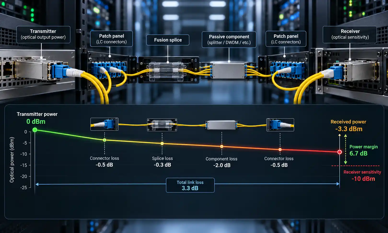
Test installed MTP LC cables with an optical loss test set or OTDR to verify performance meets specification. Measure insertion loss for each fiber pair and confirm values fall within acceptable ranges (typically 0.5dB or less for short multimode links, 0.75dB for longer runs).
The robust construction of quality MTP LC cables-particularly those featuring enhanced strain relief and reinforced jacketing-extends service life in demanding environments. Consider armored cable variants for industrial applications or areas with high mechanical stress exposure.
Key Takeaways
MTP LC cables bridge high-density MTP infrastructure with traditional LC duplex equipment across data centers, telecommunications networks, and enterprise environments
Common configurations include 8-fiber cables for 40G-to-4×10G breakouts and 12-fiber cables for versatile connectivity options
Proper polarity selection (Type A, B, or C) ensures correct transmit-to-receive fiber alignment for functional network connections
The cables enable cost-effective network migrations by connecting equipment operating at different speeds and interface types
Applications span from Ethernet and Fibre Channel to InfiniBand and broadcast video, supporting data rates from 10G through 400G