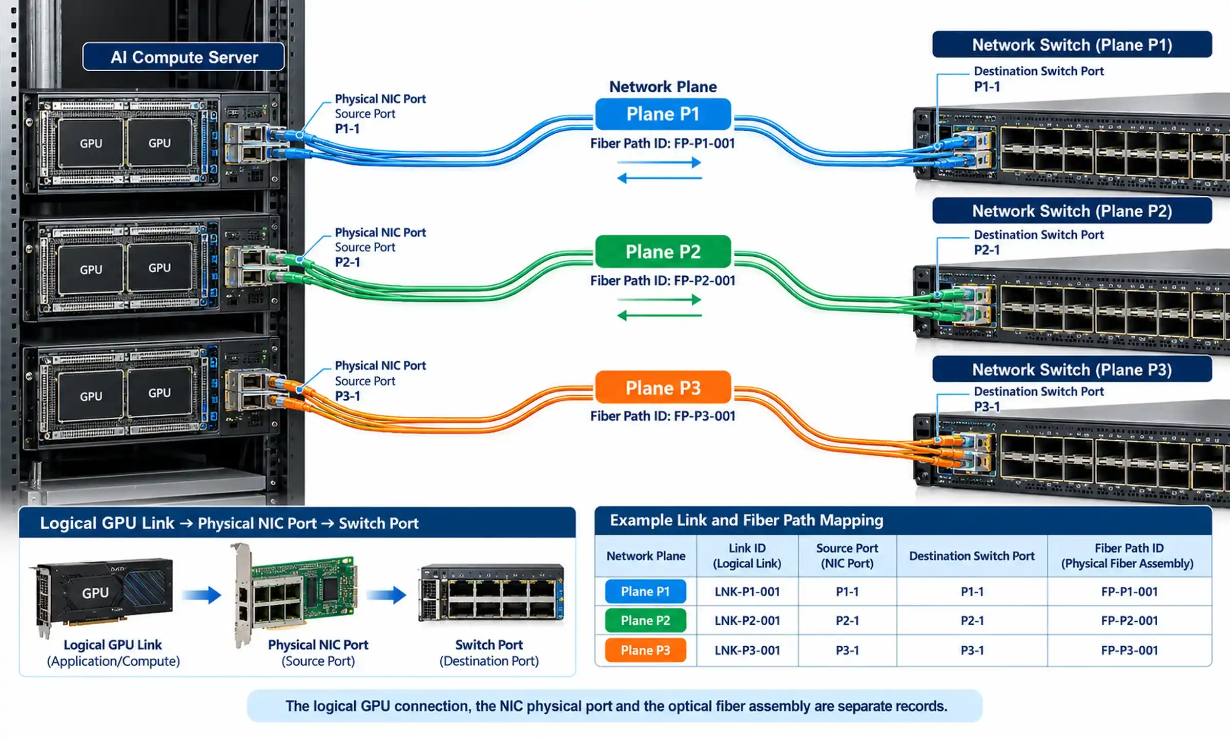
An SFP network switch can use removable transceivers or cable assemblies to connect copper Ethernet, multimode fiber, single-mode fiber, direct-attach cables, and wavelength-specific optical links. The flexibility is valuable, but it also means that a module can fit physically and still fail electrically, optically, or operationally.
A reliable link requires agreement across the complete path: the local switch port, local module, connector and cable, passive optical path, remote module, remote port, and interface configuration. This guide shows how to make those decisions in the right order, configure the port, and isolate faults without replacing equipment at random.

Quick Answer: How to Select and Configure an SFP Switch Port
- Record the exact switch model, software version, and port number.
- Confirm whether the port is SFP, SFP+, SFP28, a combo port, or a multi-rate interface.
- Choose the required data rate and then select copper, DAC, AOC, multimode fiber, or single-mode fiber.
- Match the module standard, wavelength, connector, fiber type, distance, and remote-end module.
- Check the switch manufacturer's compatibility information before purchasing.
- Install the module, verify recognition, configure the Layer 2 or Layer 3 role, and test the physical link before troubleshooting VLANs or routing.
Readers who need a basic introduction can first review what an SFP module is and how it is used.
What an SFP Switch Port Controls
The switch supplies the host-side electrical interface, power, management access, and packet-switching functions. The installed module determines the network-facing medium and optical characteristics. Depending on the port and module, the connection may use:
- An RJ45 copper SFP
- A passive or active direct-attach cable
- An active optical cable
- A duplex multimode or single-mode transceiver
- A single-fiber BiDi pair
- A fixed-wavelength CWDM transceiver
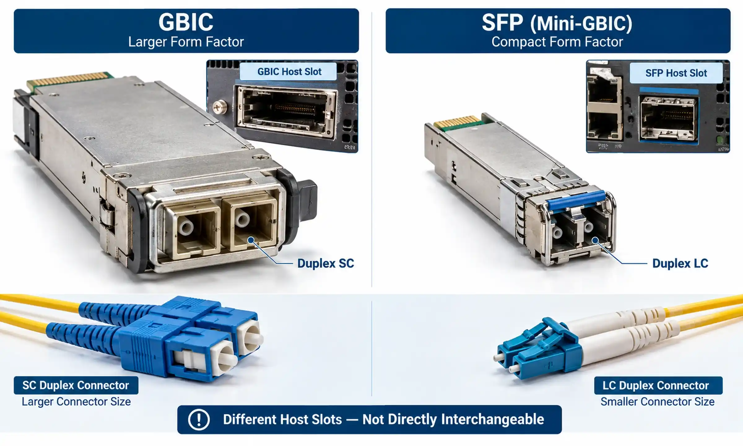
The cage shape alone does not prove compatibility. SFP, SFP+, and SFP28 modules share a similar footprint, but their signaling rates and host requirements differ. For a focused comparison of 1G and 10G form factors, see SFP vs SFP+ speed and compatibility.
Identify the Port Before Choosing a Module
Dedicated SFP or SFP+ Uplink Ports
Many access switches combine copper access ports with a smaller number of fiber-capable uplinks. The word "uplink" describes the common role, not necessarily a permanent restriction. On a managed switch, the interface may operate as an access port, VLAN trunk, routed port, or link-aggregation member when the platform supports those functions.
Check whether the port is fixed at 1G, supports 1G and 10G, or accepts multiple rates. Also confirm whether it is reserved for stacking on a particular switch model.
All-Fiber Access Ports
Industrial, campus, utility, surveillance, and data-center switches may use SFP-family ports for most access connections. Do not assume that every cage on the chassis supports the same rate. A single switch can contain separate groups of 1G, 10G, and 25G interfaces.
Combo RJ45/SFP Ports
A combo port provides an RJ45 socket and an SFP slot that share one logical interface. The two connectors may share the same port number, VLAN configuration, statistics, and administrative state. They do not create two independent ports.
Cisco's official combo-port documentation describes designs in which only one side of the pair can be active at a time. Before troubleshooting an inactive SFP slot, confirm that its paired copper interface is not already active.
Multi-Rate SFP+ and SFP28 Ports
A 10G SFP+ module cannot provide 10G service in a 1G-only SFP port. A 1G module may operate in a higher-rate cage only when the switch, the exact port, and the installed software explicitly support that mode. Compatibility must therefore be checked by device and port rather than inferred from the shape of the slot.
How to Select the Right SFP Module
1. Confirm the Form Factor, Speed, and Platform Support
Begin with the complete switch model and port number. Confirm the supported Ethernet rates, whether the interface is single-rate or multi-rate, and whether a lower-speed optic requires manual port configuration. Also check restrictions for stacking, breakout, DAC, AOC, or high-power copper modules.
Use the vendor's current compatibility tool rather than a generic product list. Cisco provides an official transceiver compatibility information page, while Juniper provides a searchable Hardware Compatibility Tool.
2. Choose the Transmission Medium
| Medium | Typical use | Main checks |
|---|---|---|
| RJ45 copper SFP | Reusing a supported twisted-pair link | Supported speed, cable category, reach, power, heat, and auto-negotiation behavior |
| Passive DAC | Short links in the same rack or between adjacent devices | Host coding, supported cable length, and bend management |
| Active DAC or AOC | Short equipment-room links beyond passive-DAC limits | Compatibility at both ends and the fixed cable assembly |
| Multimode optical module | Short and medium in-building fiber links | OM grade, link length, connector, wavelength, and channel condition |
| Single-mode optical module | Campus, building-to-building, and longer links | OS2 path, optical budget, receiver limits, and passive losses |
3. Match Fiber Type, Module Standard, and Distance
The installed fiber should guide the module choice. Common starting combinations include 1000BASE-SX or 10GBASE-SR on multimode fiber and 1000BASE-LX or 10GBASE-LR on single-mode fiber. The exact supported reach still depends on the module datasheet and the installed cable grade.
For a broader decision framework, compare single-mode and multimode fiber by distance and speed. When working with legacy multimode infrastructure, also review the differences among OM1, OM2, OM3, and OM4 fiber.
Examples of modules available for common links include:
- 1000BASE-SX SFP for multimode fiber
- 1000BASE-LX/LH SFP for single-mode fiber
- 10GBASE-SR SFP+ for multimode fiber
- 10GBASE-LR SFP+ for single-mode fiber
These pages are useful starting references, but the switch compatibility matrix and the actual installed channel remain the final decision criteria.

4. Match Wavelength, Connector, and Fiber Arrangement
Confirm the transmit and receive wavelengths, connector type, fiber mode, and whether the link uses duplex or single-fiber transmission. Many commonly used SX, LX, SR, and LR modules use duplex LC interfaces, but copper, BiDi, CWDM, and parallel-optics products follow different designs.
Do not rely on cable jacket or latch color as the only identification method. Read the module label and datasheet. The site guide to common fiber connector types can help when an installed patch panel does not use the expected LC interface.
BiDi modules must be installed as complementary wavelength pairs. Cisco's official 10GBASE SFP+ module data sheet, for example, describes one BiDi endpoint transmitting at 1330 nm and receiving at 1270 nm, while the paired endpoint performs the reverse operation.
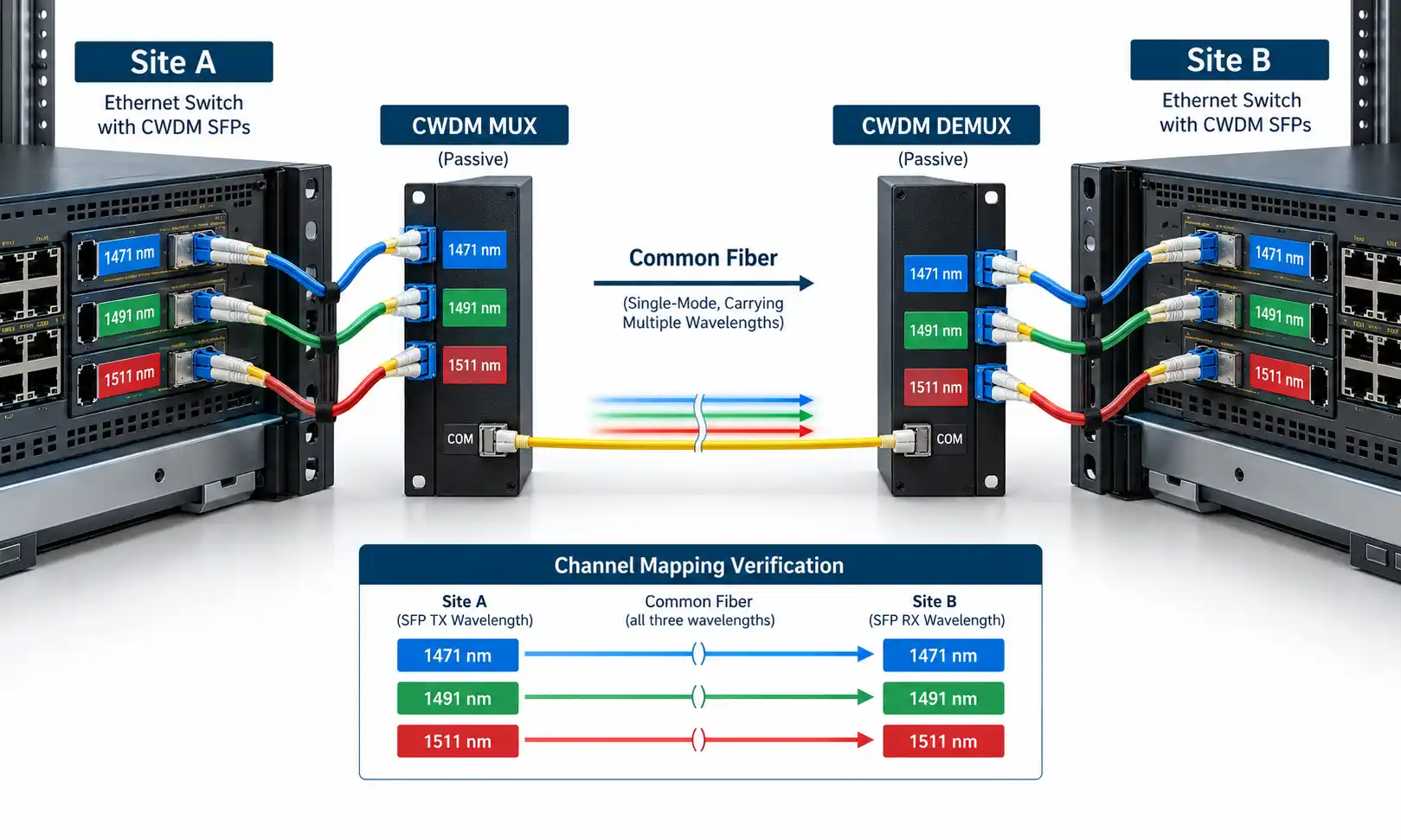
For networks carrying several wavelength channels over limited fiber, a CWDM SFP must also match the assigned MUX/DEMUX channel.
5. Check the Complete Optical Path
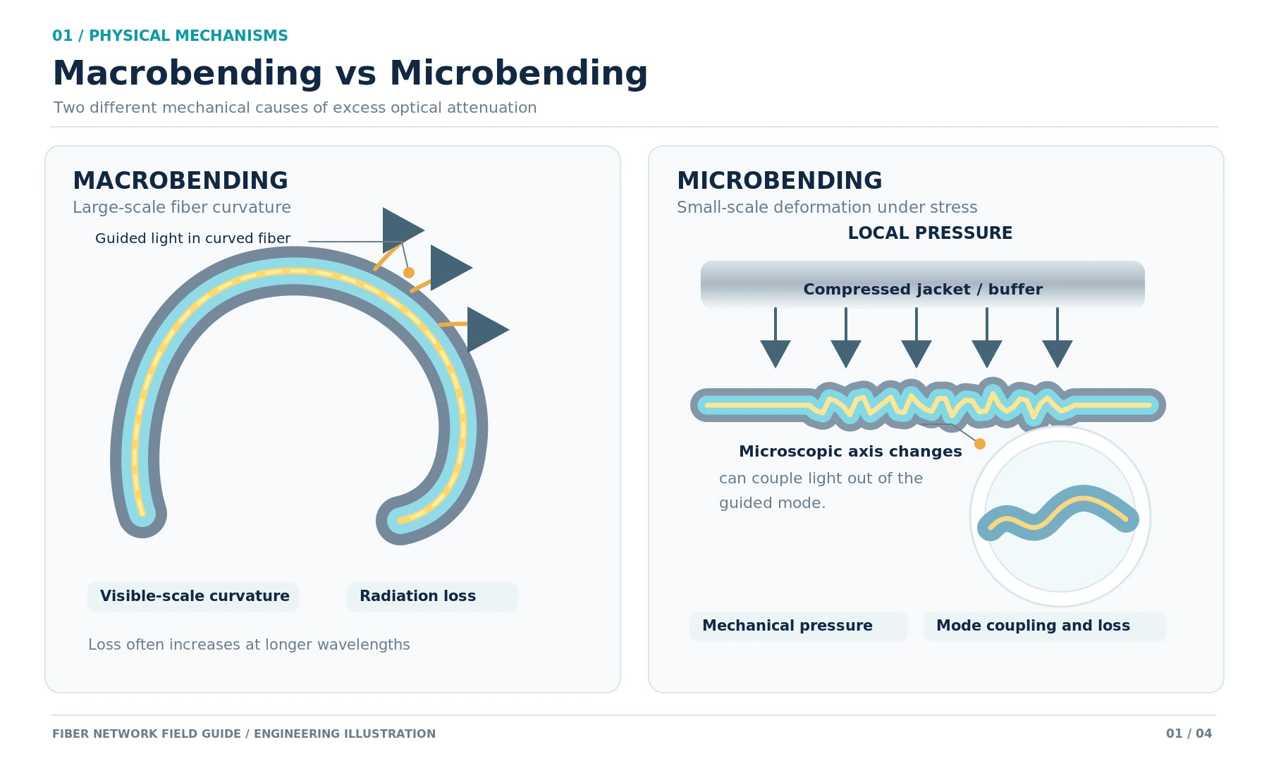
The module's advertised reach is not a guarantee that every link below that distance will work. The channel can include fiber attenuation, patch cords, adapters, connector pairs, splices, patch panels, wavelength multiplexers, and engineering margin.
Use the following relationship:
Available optical budget = minimum transmitter output − receiver sensitivity
As a worked example, Cisco lists a minimum transmit power of -8.2 dBm and a minimum receive level of -14.4 dBm for its 10GBASE-LR module. The available budget is therefore 6.2 dB. The estimated loss of the complete channel, including design margin, must remain below that figure. The number is specific to that module specification and must not be reused for a different optic without checking its datasheet.
Long-reach optics can also overload a receiver on a short path. When attenuation is required, review the available fiber optic attenuator options and use the module manufacturer's limits to select the value.
6. Consider DOM, Temperature, Power, and Coding
Digital Optical Monitoring, also called DDM on some product pages, can report transmit power, receive power, temperature, supply voltage, and laser bias current. It is useful during commissioning and fault isolation, but it is not available on every module or host platform.
Juniper's official DOM command reference explains that alarm and warning thresholds are set by the transceiver vendor. For that reason, a generic "normal Rx value" should not be applied to every optic.
In outdoor cabinets or industrial environments, verify the module's own operating-temperature range. A rugged switch does not make a commercial-temperature transceiver suitable for the same conditions. In high-density installations, also check the chassis power and thermal limits before filling ports with high-power copper modules.
How to Read an SFP Module Specification
Before ordering, translate the product label or datasheet into a small set of link decisions. Marketing names are not enough; the fields below determine whether the module belongs in the planned path.
| Specification field | What it tells you | Why it matters |
|---|---|---|
| Form factor | SFP, SFP+, SFP28, or another package | The module must match a supported host cage and interface type. |
| Ethernet standard | Examples include 1000BASE-SX, 1000BASE-LX, 10GBASE-SR, and 10GBASE-LR | The standard identifies the nominal rate, medium, and interoperability target. |
| Wavelength | The transmit and receive wavelength or BiDi wavelength pair | Both endpoints and any CWDM equipment must use the correct optical channel. |
| Fiber and connector | Single-mode or multimode fiber, plus LC, RJ45, or another interface | The installed cable and patch-panel interfaces must match. |
| Reach | The vendor's supported distance under stated conditions | Reach must be checked together with channel loss and receiver limits. |
| Tx and Rx limits | Output-power range, receiver sensitivity, and overload level | These values define the available optical budget and whether attenuation may be needed. |
| DOM or DDM | Whether the module exposes live diagnostic values | Useful for commissioning, alarms, and comparing both ends of a failing link. |
| Temperature and coding | Commercial, extended, or industrial range and intended host platform | A technically suitable optic can still be rejected by the switch or fail outside its rated environment. |
Do not choose a module from the distance field alone. A complete review should produce one consistent statement: this port supports this form factor and rate; this optic matches the installed fiber and remote optic; and the calculated channel loss remains inside the module's Tx and Rx limits.
Quick Module Selection Matrix
| Requirement | Starting option | Confirm before purchase |
|---|---|---|
| Short 1G copper connection | 1000BASE-T SFP | Host support, negotiated speeds, cable category, reach, and heat |
| 1G in-building multimode link | 1000BASE-SX | OM grade, channel length, wavelength, and LC polarity |
| 1G building-to-building link | 1000BASE-LX over OS2 | Optical budget, remote module, and connector condition |
| Short 10G same-rack link | Passive SFP+ DAC | Compatibility at both ends and maximum supported cable length |
| 10G in-building fiber link | 10GBASE-SR over OM3 or OM4 | Installed fiber grade and channel reach |
| 10G campus or building link | 10GBASE-LR over OS2 | Total channel loss and receiver input limits |
| Only one fiber strand is available | Complementary BiDi pair | Tx/Rx wavelength pairing at both ends |
| Several services share limited fiber | CWDM SFP/SFP+ system | Channel plan, MUX loss, and optical budget |
Common cabling choices include OS2 single-mode patch cords for LR or LX links and OM4 multimode patch cords for suitable SR links.
Three Practical Selection Scenarios
10G Connection Inside One Rack
When a server adapter and top-of-rack switch both support the same SFP+ DAC assembly, a short passive DAC is usually the simplest starting choice. It removes two optical connectors and two separate transceivers from the path. The decision still depends on the supported cable part number and maximum qualified length at both endpoints.
1G Link Between Buildings
For an existing OS2 route between two equipment rooms, a compatible 1000BASE-LX pair is a common starting design. Confirm the path termination, connector polish, complete loss budget, and VLAN role at both ends. The fact that the route is shorter than the module's advertised reach does not remove the need to check receiver input and passive losses.
Single-Fiber Link
When only one usable strand is available, select a complementary BiDi pair rather than two identical modules. Record the Tx and Rx wavelengths for both ends before installation, because a correctly recognized module will still show no optical link when the wavelength pairing is wrong.
How to Configure an SFP Port on a Network Switch
Configuration syntax varies by vendor, switch family, interface type, and software version. Treat the following as a workflow rather than a universal command set.
1. Install the Module and Confirm Recognition
Seat the supported module fully, secure the latch, and check the switch inventory and event log. Confirm the detected part number, media type, speed, and diagnostic capability. If the switch reports an unsupported transceiver, solve the compatibility or coding problem before changing VLAN settings.
2. Enable the Interface and Confirm the Operating Rate
Make sure the port is administratively enabled and is not error-disabled by a security, loop, link-flap, or unsupported-module event. On a multi-rate port, verify the actual operating speed at both endpoints. Do not copy a speed or duplex command from an unrelated platform.
3. Choose the Network Role
An access port normally carries one untagged VLAN. A trunk carries multiple tagged VLANs between switches, routers, firewalls, hypervisors, or controllers. Some platforms also allow an SFP interface to operate as a routed Layer 3 port. The label "uplink" does not automatically determine any of these roles.
4. Configure VLANs and Link Aggregation
For an access port, verify that the access VLAN exists and matches the endpoint design. For a trunk, check the allowed VLAN list and native or untagged VLAN behavior at both ends. Cisco's official VLAN trunk configuration guide notes that a VLAN must be active and allowed on the trunk before it can pass traffic.
When several SFP links form one logical port channel, configure compatible LACP mode, speed, VLAN, native VLAN, MTU, and member settings on both devices. Link aggregation increases capacity across multiple flows; it does not guarantee that one individual session will use the sum of all member links.

Illustrative Cisco IOS XE Trunk Example
The interface name, description, and VLAN numbers below are placeholders. Confirm the syntax for the exact switch and software release before applying it.
interface TenGigabitEthernet1/1/1
 description Uplink-to-distribution-switch
 switchport mode trunk
 switchport trunk allowed vlan 10,20,30
 no shutdown
After configuration, typical verification tasks include checking interface status, the negotiated speed, the detected transceiver, the active trunk VLANs, and error counters. The command names differ by platform, so use the device's own command reference.
5. Review MTU and FEC Only When the Design Requires Them
Establish a working link with standard settings before adding jumbo frames or other optimizations. For 25G and some higher-rate links, verify whether Forward Error Correction is required and confirm that both endpoints use compatible FEC behavior. Do not apply 25G assumptions to every 1G or 10G SFP link.
Verify the Link in Three Layers
Physical Layer
- Module is recognized at both ends
- Interface is up at the expected rate
- DOM readings are within the module's own warning and alarm thresholds
- No unexpected temperature, CRC, input-error, or link-flap alarms appear
When field verification is required, compare DOM with a suitable optical power measurement procedure rather than treating DOM as a replacement for every calibrated test instrument.
Layer 2
- Access or trunk mode matches the remote interface
- Required VLANs exist and are allowed
- Native or untagged VLAN behavior is consistent
- MAC addresses are learned on the expected VLAN
- STP and LACP states are correct
Layer 3 and Application
- IP addressing and routing are correct
- The directly connected peer responds as expected
- The required application is reachable
- Throughput tests are interpreted separately from server, storage, or firewall limitations
SFP Port Troubleshooting Decision Order
- Confirm port support. Verify the form factor, supported rate, exact port, and software version.
- Check module recognition. Resolve unsupported-transceiver, seating, or coding messages first.
- Compare both endpoints. Match speed, Ethernet standard, fiber mode, wavelength, and connector arrangement.
- Inspect the passive path. Verify polarity, patching, connector cleanliness, splices, MUX channels, and any attenuator.
- Read DOM and counters. Compare values with the module's thresholds and review CRC errors, drops, alarms, and flaps.
- Check VLAN, STP, and LACP. A green link light proves only that the physical link is present.
- Swap one component at a time. Replacing several parts simultaneously can restore service while hiding the original cause.
For a separate fault-isolation reference, see the site's guide to troubleshooting transceivers and switch ports.

Common Mistakes to Avoid
- Assuming physical fit means compatibility: similar cages do not guarantee the same signaling rate or platform support.
- Choosing the optic before identifying the installed cable: the existing fiber type and channel condition should influence the module choice.
- Ignoring the remote end: both host ports, both modules, and the passive path form one system.
- Installing two identical BiDi modules: most BiDi links require complementary Tx and Rx wavelengths.
- Using both sides of a combo port: the RJ45 socket and SFP slot normally share one logical interface.
- Treating an uplink as an automatic trunk: physical media and VLAN configuration are separate decisions.
- Replacing optics before cleaning and testing the path: contamination, reversed polarity, and excessive loss can imitate a failed module.
FAQ
Q: Does an SFP port need to be configured?
A: A supported module may be detected automatically, but the interface still needs the correct administrative state and network role. That can include speed selection, access or trunk mode, VLAN membership, LACP, MTU, routing, or FEC, depending on the platform and link.
Q: Can a 1G SFP work in a 10G SFP+ port?
A: Sometimes. The exact SFP+ port and software release must support 1G operation. Physical insertion alone does not confirm that support.
Q: Can a 10G SFP+ module work in a 1G SFP port?
A: No. A 1G-only host port cannot operate a 10G SFP+ module at 10G.
Q: Do both ends need the same module?
A: They need compatible Ethernet standards, wavelengths, fiber types, connector arrangements, and optical power ranges. Duplex links often use matching module standards, while BiDi links normally use complementary wavelength pairs.
Q: Why is the SFP link up but not passing traffic?
A: Common causes include different access VLANs, a missing VLAN on the trunk, native-VLAN mismatch, STP blocking, LACP mismatch, incorrect IP addressing, or routing. Once the physical link is up, troubleshoot Layer 2 and Layer 3 separately.
Q: Can a third-party SFP module be used?
A: Possibly, but acceptance and support policies vary. Confirm coding, platform support, software requirements, DOM behavior, operating temperature, and the supplier's replacement policy before deployment.
Final Procurement and Deployment Checklist
Before Ordering
- Exact switch model, software release, and port number
- Required rate and port form factor
- Remote device and remote port capability
- Copper, DAC, AOC, multimode, or single-mode medium
- Fiber grade, connector, polarity, wavelength, and distance
- Optical budget and maximum receiver input
- Vendor coding, DOM, temperature, power, and thermal requirements
Before Handover
- Module recognition and correct operating rate at both ends
- Recorded DOM readings and error counters
- Verified VLAN, trunk, LACP, STP, MTU, and FEC settings where applicable
- Successful Layer 3 and application tests
- Labels and documentation for both endpoints, modules, fiber route, and installation date
A dependable SFP network switch link is not created by selecting the longest-reach or most expensive transceiver. It is created by matching every component and configuration across the complete path, then verifying the physical, Layer 2, and Layer 3 results in order.