DWDM SFP模块不能仅凭距离选择.主机端口,数据速率,中心频率,通道间距,多模/双多工端口,远程光学,光功率限制和软件支持都必须属于同一设计.

最常见的混淆点是通道识别.产品可能以太赫兹为单位的频率,以纳米为单位的波长,ITU信道号或厂商特定代码来标注.这些标签仅在指向相同中心频率时才有用.
本指南重点介绍选择和部署DWDM SFP和SFP+模块时的重要决策.需要更广泛介绍的读者可以先了解DWDM技术的工作原理.
快速回答:如何选择DWDM SFP模块
- 确定具体的交换机,路由器,线路卡,端口和支持的数据速率.
- 确认光线系统使用的是100 GHz,50 GHz或其他信道网格.
- 将模块中心频率与指定的多模/双重混音通道匹配.
- 确认远程模块和服务另一端的光学方向.
- 计算完整的光路径,包括无源器件损耗和接收机过载限制.
- 下单前请核实主机编码,软件,功率,温度和可调信道支持.
更窄的通道网格并不一定是更好的设计.正确的模块应符合已安装的线路系统和运营需求.
DWDM SFP模块的作用
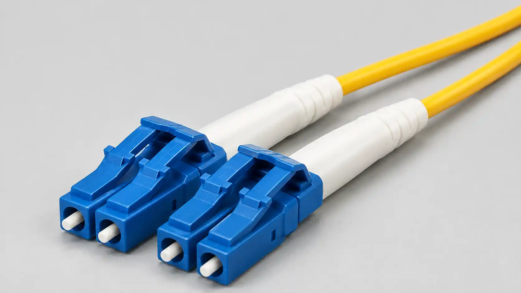
DWDM SFP模块是一种紧凑型光学收发器,能够在定义的密集波分复用中心频率上发送客户端服务.多个模块可以将不同信道输入一个光复用器,使多个服务共享同一对单模光纤.
该类别可以包括固定波长1G SFP模块,固定波长10G SFP+模块以及可调谐的10G SFP+模块.可用的DWDM SFP模块只是链路的一部分.完整路径还需要正确的通道滤波器,线路光纤,远程光纤和主机设备.
传统的灰色光学镜则不同.它为专用链路提供了非DWDM光接口,而不是通过DWDM滤波系统而设计的严格控制通道.
ITU DWDM 频网的工作原理
193.1 太赫兹参考点
ITU-T G.694.1 频谱-网格建议定义了从193.1 THz为参考点出发的固定DWDM频率.固定网格信道间距包括12.5,25,50和100 GHz,并可选择更宽的间距选项.
对于固定网格,邻近频率由参考频率计算:
信道频率 = 193.1 THz + n × 信道间隔
在这种关系中,n 是正整数或负整数.当模块标签和多路输入器标签使用不同信道号约定时,频率值通常是最安全的标识符.
为什么GHz比圆滑波长更可靠
频率和波长描述的是相同的光载波,但它们的关系并非线性.在1550纳米附近,100 GHz约为0.8纳米,50 GHz约为0.4纳米.波长差在波段中略有变化.
以下小例子展示了193.1 THz参考点周围的关系:
| 中心频率 | 近似波长 | 与193.1太赫兹的关系 |
|---|---|---|
| 193.00 太赫兹 | 1553.33 nm | 比100 GHz低一级 |
| 193.05 太兹 | 1552.93 nm | 再低一级50 GHz |
| 193.10 太赫兹 | 1552.52 nm | 参考频率 |
| 193.15 太赫兹 | 1552.12 nm | 比50 GHz高一级 |
| 193.20 太赫兹 | 1551.72 nm | 比100 GHz高一级 |
这些波长数值经过四舍五入.采购记录应保留中心频率,模块零件号和多路输出端口标签,而非仅依赖波长.

100 GHz vs 50 GHz DWDM SFP Modules
A 100 GHz grid places adjacent channels approximately 0.8 nm apart near 1550 nm. It is widely used in fixed-channel passive DWDM systems and is often easier to provision when the required channel count fits the selected platform.
Cisco's official fixed DWDM SFP data sheet describes a 100 GHz product family with 40 fixed-wavelength SFP models. FOCC also lists 100 GHz DWDM solutions for systems built around that grid.
A 50 GHz grid places channels approximately 0.4 nm apart near 1550 nm. The denser grid can support more channel positions within a similar spectral range, but it requires matching filters, accurate wavelength control, and more disciplined provisioning.
| Decision factor | 100 GHz grid | 50 GHz grid |
|---|---|---|
| Approximate spacing near 1550 nm | 0.8 nm | 0.4 nm |
| Typical module approach | Commonly fixed wavelength; tunable options may also exist | Frequently used with tunable modules |
| Required passive or active line system | 100 GHz filters and channel plan | 50 GHz filters and channel plan |
| Provisioning complexity | Usually lower for a stable passive system | Higher when channels are frequently reassigned |
| Spare strategy | Channel-specific fixed spares unless tunable optics are supported | A tunable spare may cover many supported frequencies |
| Best reason to choose it | The channel count and system design already fit 100 GHz | The network genuinely needs the denser grid or reconfigurable operation |
Channel-spacing labels alone do not prove cross-grid interoperability. The exact center frequency, transmitter characteristics, filter passband, insertion loss, and system qualification must all be checked.
Fixed-Wavelength vs Tunable DWDM SFP Modules
Fixed-Wavelength Modules
A fixed-wavelength module is manufactured for one center frequency. It is straightforward to deploy because no channel-setting command is required. This makes it well suited to stable passive links in which each endpoint has a permanent channel assignment.
The main operational cost is spare inventory. A fixed module for one frequency normally cannot replace a failed module assigned to another frequency.
Tunable DWDM SFP+ Modules
A tunable module can be configured to one of several supported frequencies. This can reduce channel-specific spare inventory and simplify service restoration in larger networks.
Cisco's 10G DWDM SFP+ data sheet documents fixed modules using 40 non-tunable 100 GHz wavelengths and tunable models supporting 96 selectable 50 GHz wavelengths. These are product-specific capabilities rather than universal channel limits.
Tunability also creates new dependencies. The host must support the module, expose a valid tuning method, preserve the configured channel as required, and supply the necessary power. The selected frequency must also match the MUX, optical add-drop multiplexer, or reconfigurable optical add-drop multiplexer path.
| Choose fixed wavelength when | Choose tunable when |
|---|---|
| The channel plan is stable and relatively small. | The system carries many channels or assignments change frequently. |
| The host does not support wavelength tuning. | The host and software explicitly support the intended tunable module. |
| Channel-specific spare inventory is manageable. | Reducing spare types has meaningful operational value. |
| The link uses a simple passive MUX/DEMUX design. | The network includes reconfigurable optical paths or rapid service restoration. |
How to Match the Module, MUX, and Remote End
1. Start with the Line-System Grid
Identify whether the installed DWDM MUX/DEMUX, OADM, or ROADM uses 100 GHz, 50 GHz, or another supported grid. The optical system defines the usable channel plan.
2. Read the Channel-Port Label Carefully
A channel port may be labeled by frequency, wavelength, ITU channel number, or a vendor code. The guide to ports on CWDM and DWDM MUX/DEMUX equipment provides additional context on common-port, channel-port, monitor, and expansion interfaces.
Record every available identifier, but use the center frequency as the primary technical reference.
3. Match the Local Module
A fixed module must be manufactured for the assigned center frequency. A tunable module must support that frequency and be configured through a method supported by the host platform.
4. Follow the Complete Optical Path
The path should be reviewed in this order:
Local host port → local DWDM module → local channel port → common line port → OS2 line fiber → remote common port → remote channel port → remote DWDM module → remote host port
The common line normally uses OS2 single-mode fiber and patch cords. Connector polish and interface type must match the equipment specification.
5. Verify the Remote-End Design
In a conventional dual-fiber point-to-point service, the corresponding endpoints normally follow the same assigned center frequency through the MUX and DEMUX. Single-fiber, ring, OADM, and ROADM systems can use different directional rules, so their port map must be followed rather than inferred.
6. Confirm Host Compatibility
An optically correct module can still be rejected by the switch or router. Use the exact device, line card, port, and software release when checking the Cisco optics compatibility matrix or the relevant host manufacturer's official support information.

Optical Power Budget and Receiver Overload
A distance label such as 40 km or 80 km is not a complete link budget. Passive DWDM filters, OADMs, connectors, splices, fiber attenuation, and engineering margin all consume optical power.
Available optical budget = minimum transmitter output − receiver sensitivity
Estimated path loss = fiber loss + connector loss + splice loss + MUX/DEMUX loss + OADM loss + engineering margin
Worked Example Using Published Module Limits
Cisco publishes a minimum transmitter output of 0 dBm and a minimum receiver input of -28 dBm for its fixed 1G DWDM SFP family. Based on those published limits:
Available optical budget = 0 dBm − (-28 dBm) = 28 dB
The network designer must then subtract the actual published losses for both passive filters, the measured or designed fiber loss, connectors, splices, any OADM, and the selected engineering margin. Values from another module or another MUX must not be substituted without checking their own data sheets.
The same data sheet lists a maximum normal receiver input of -9 dBm and warns that short links may require attenuation. This illustrates why a long-reach optic can fail on a path that is too short as well as on one that is too lossy. When attenuation is required, use the receiver limit and a suitable fiber optic attenuator rather than choosing a value by guesswork.

What Else Must Match Besides the Channel?
Data Rate and Protocol
A correct wavelength cannot solve an electrical mismatch. Confirm whether the port requires 1G SFP, 10G SFP+, or another form factor, and whether the module supports Ethernet, Fibre Channel, OTN, or the required client protocol. The broader fiber optic transceiver range helps distinguish DWDM products from gray, BiDi, and higher-speed alternatives.
DOM, Temperature, and Power
Digital Optical Monitoring can report transmit power, receive power, temperature, supply voltage, laser bias current, and alarm thresholds. Compare readings with the module's own limits rather than using one generic acceptable range.
For outdoor or industrial deployment, confirm the module's temperature rating separately from the switch rating. Tunable modules may also require host power and thermal support that a standard SFP+ port does not provide.
Passive, Add-Drop, and Reconfigurable Systems
A passive point-to-point system combines channels at one end and separates them at the other. An optical add-drop multiplexer can insert or remove selected wavelengths at an intermediate location, while a ROADM can reconfigure optical paths under management control.
The distinction is explained further in OADM vs ROADM. FOCC also lists fiber OADM options for fixed add-drop applications.
Application Selection Matrix
| Application | Likely starting approach | Fixed or tunable | Main design constraint |
|---|---|---|---|
| Small enterprise or campus backbone | Passive 100 GHz system when the selected platform has enough channels | Often fixed | Complete optical budget and stable channel documentation |
| Metro access and aggregation | 100 GHz or 50 GHz according to the installed line system | Fixed or tunable | Passive loss, reach, add-drop requirements, and operational changes |
| Data center interconnect over dark fiber | Traditional DWDM SFP/SFP+ for suitable 1G or 10G services | Depends on service scale | Loss, dispersion, OSNR, and the boundary between direct-detect and coherent transport |
| ROADM-based network | The grid and passband specified by the optical line system | Usually tunable where supported | Host tuning support and end-to-end route qualification |
| Fiber-constrained service expansion | Add unused DWDM channels to the existing system | Depends on spare strategy | Available filter ports and remaining optical margin |
Typical DWDM SFP Applications
Enterprise and Campus Backbones
When one OS2 fiber pair must carry several network, storage, surveillance, or management services, a passive DWDM system can add capacity without installing one new pair per service. The design should remain simple enough for the local team to document and maintain.
Metro Access and Aggregation
DWDM SFP modules can transport multiple 1G or 10G services across limited metro fiber. Shorter links may use passive filters, while longer or multi-node routes may require amplification, add-drop equipment, dispersion review, or a transponder. The site's overview of DWDM system components explains how these elements fit together.
数据中心互联
传统的DWDM SFP和SFP+模块适用于通过合格暗光线传输的单个1G或10G服务.高容量互连可能需要相干模块或专用光传输系统,而非传统的DWDM SFP信道集合.
长距离与多节点传输
随着距离和节点数量的增加,滤波器损耗,色散,光信噪比和接收机限制变得更加重要.在假设单靠长距离模块额定值就足够之前,先审查长距离DWDM传输.
当DWDM的SFP不是最佳选择时
- 只需一条短的点对点链路,标准的LR或ER光学系统已满足需求.
- 备用的暗光纤随处可见,波长复用会增加不必要的操作工作.
- 只需要几个通道,CWDM可能是更简单的选择.
- 主机不支持所需的固定或可调模块.
- 安装的滤波器使用不同的网格或不支持的渠道布局.
- 该路由需要再生,协议转换或相干传输,而非直接插拔光学.
- 运营团队无法保持准确的信道,电力和终端记录.
常见的DWDM SFP选择错误
- 仅按波长购买:保持准确的中心频率和零件编号.
- 假设50 GHz总是更好:密集间距只有在线路系统和操作支持时才有用.
- 忽略滤波器损耗:两个多路/双重多行单元和中间OADM可能会占用大量可用预算.
- 检查灵敏度但不过载:短链路可能需要衰减.
- 假设每个可调模块都能在每个SFP+端口下工作:调谐,电气接口,电源和软件需求各不相同.
- 将收发器视为完整系统:信道滤波器,线路光纤,远端和管理流程同样重要.
- 未能记录信道:未记录的波长变化可能导致难以隔离的断线.
常见问题
问:DWDM的信道间隔是以GHz还是nm计量?
答:标准化网格以GHz为单位的频率定义.纳米间距在特定波长附近是一个有用的近似值,但在光波段中略有变化.
问:两端都需要相同的DWDM通道吗?
答:在传统的双光纤点对点服务中,相应端点通常通过多路复用和多工(DEMUX)使用相同的中心频率.单光纤,环形,OADM和ROADM设计必须遵循其文档中的定向信道计划.
问:100 GHz 模块可以与 50 GHz 多路交流器一起使用吗?
答:仅靠空格标签无法回答这个问题.模块中心频率必须与所选滤波器端口对齐,发射机特性,滤波器通带,插入损耗,接收机限制和系统鉴定都必须兼容.
问:DWDM SFP需要多路兼容/脱多工(MUX)吗?
答:DWDM模块可以在没有多路复用设备的情况下发射其分配的波长,但除非使用兼容的复用和解复用设备,否则多个波长无法共享同一线路光纤.
问:何时应使用可调的DWDM SFP+?
答:可调光学设备在主机支持且网络有多个信道,频繁波长变化,ROADM环境或强烈减少信道专用备件库存时最为有用.
问:不同的数据速率可以共用一条DWDM光纤吗?
答:当每个服务使用支持的信道,并且多路/双重通行(MUX/DEMUX)通带,模块协议,光学预算和系统架构支持组合时,它们可以共享线路系统.