10GbE Setup
If you only read one section, read this one:
- Both ends of every link need a 10GbE interface. One fast NIC does not create a fast link.
- The media between them must be compatible with both ports: Cat6A for RJ45, DAC or optics for SFP+.
- Two devices can be connected directly. A switch is only needed once a third device joins.
- Leave MTU at 1500 during commissioning. Jumbo frames are an optimisation, not a requirement.
- Prove the network with iperf3 first. Only then blame the NAS, the CPU or the protocol.
- Everything below explains how to make those five decisions correctly, and how to tell which component is holding the link back when the numbers disappoint.
What Do You Need for a 10GbE Network?
A minimal 10GbE link is two capable endpoints and a compatible connection between them. A larger network adds a switch with enough 10GbE ports.
- 10GbE network interface cards, or onboard 10GBASE-T ports
- A 10GbE switch - unless the two devices are connected directly
- Copper cabling, DACs, AOCs, or transceivers plus fiber
- Hosts and storage fast enough for the intended workload
- Drivers, firmware and OS support for the selected hardware
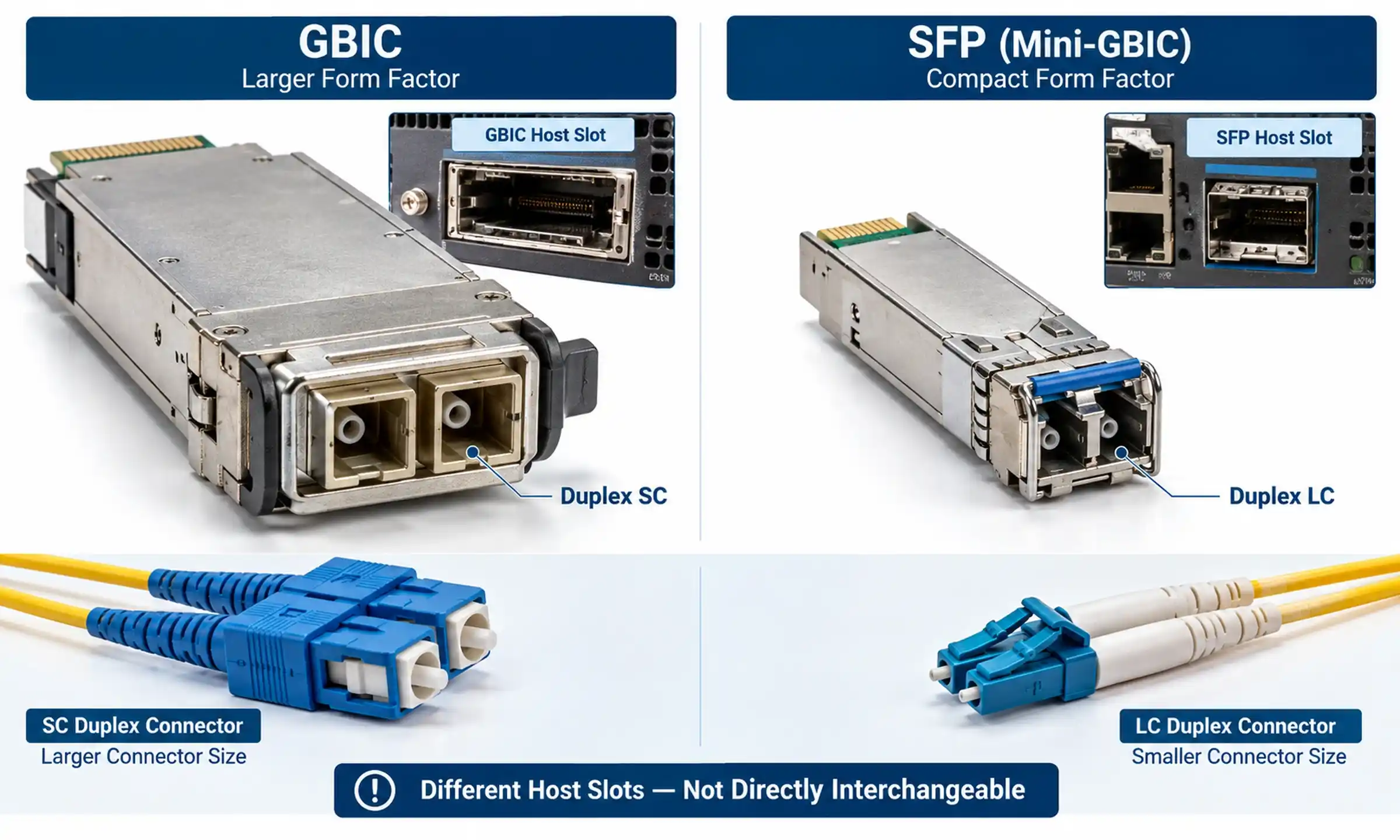
The operative word is compatible. An SFP+ port will not accept an RJ45 patch lead unless a supported 10GBASE-T SFP+ module or media converter sits in between, and SFP+ is a port and module form factor, not a fiber connector - optical SFP+ modules almost always terminate in duplex LC.
Choosing the Network Interface Card
Before ordering a NIC, four things decide whether it will actually run at 10Gbps: the slot must be physically available; the slot must supply enough usable PCIe bandwidth (a card can fit an x8 slot that is electrically wired x1); the driver must exist for your kernel or server release; and the card must not cook itself in a passively cooled desktop. Older server pulls and some 10GBASE-T silicon run notably hot.
The most common surprise here is lane allocation. A NIC seated in a chipset-attached slot that shares bandwidth with an M.2 drive will negotiate a narrower PCIe link, and the operating system will happily report "10Gbps" on the Ethernet side while the bus quietly caps you at 6–7Gbps.
Switch or Direct Connection?
A switch is not always necessary. A direct link works well when exactly two systems need the bandwidth - a video-editing workstation and a NAS, for example - with a static address pair on a dedicated subnet.
Move to a switched design when more than two devices need 10GbE, when several workstations hit the same storage pool, when the 10GbE segment must reach the existing LAN, or when VLANs and centralised management matter. When you do, count ports honestly: an eight-port switch loses ports fast to NAS links, router uplinks and inter-switch connections.
Storage and Host Performance
A 10GbE link has a line rate of 10 gigabits per second. A file transfer has nothing of the sort. It is bounded by drive count and RAID layout, NAS CPU, SSD cache behaviour, file-system overhead, SMB or NFS configuration, encryption, client CPU, PCIe bandwidth and the number of users sharing the pool.
That is why a network benchmark and a file-transfer benchmark are two different tests, and why the order in which you run them matters more than any tuning parameter.
Do You Actually Need 10GbE?
10GbE earns its cost where a local network regularly moves bulk data or serves many simultaneous clients: editing high-resolution video from shared storage, moving project files between workstations and a NAS, backing up multiple systems to one server, running VMs from network storage, replicating between servers, or providing a high-capacity uplink between switches.
It does not make an internet connection faster. It improves traffic only where the complete path supports the higher rate.
When 2.5GbE or 5GbE Is the Better Buy
A multigigabit upgrade is often the smarter money when most endpoints already have 2.5GbE onboard, when the storage system cannot approach 10Gbps anyway, when the dominant workload is internet access rather than local transfer, or when the cabling cannot be replaced.
A common and effective small-office pattern: 2.5GbE at the desks, 10GbE between switches, servers and storage. The bandwidth goes where the traffic converges instead of being sprayed across ports that will never use it.
Requirement, Topology and Media
| Situation | Topology | Media to evaluate first |
|---|---|---|
| Two devices, same room, under 3 m, SFP+ ports both ends | Direct connection | Passive SFP+ DAC |
| Workstation and NAS, same room, RJ45 ports both ends | Direct connection | Cat6A patch lead |
| Office cabling inside walls, up to 100 m | Partial 10GbE upgrade | Installed and tested Cat6A channel |
| Between floors, or through electrically noisy plant areas | Partial or switched | OM3/OM4 multimode with SR optics |
| Between buildings, or infrastructure meant to outlive 10G | Switched | Single-mode fiber with LR optics |
| Several workstations sharing one NAS or server | Switched 10GbE | 10GbE switch plus mixed DAC/fiber/Cat6A |

RJ45, DAC or Fiber?
| Connection | Typical use | Strengths | Limitations |
|---|---|---|---|
| 10GBASE-T RJ45 | Structured cabling, wall outlets | Familiar connector, backward negotiation on supported ports | Commonly draws more power and runs warmer than a short DAC link |
| SFP+ DAC | Same rack or adjacent equipment | Low component count, low cost, nothing to clean | Fixed assembly, limited reach, stiff bend radius |
| SFP+ AOC | Short links where cable bulk is a problem | Thinner and lighter than DAC, electrically isolated | Transceiver ends are not replaceable |
| 10GBASE-SR | Building and equipment-room multimode links | Flexible patching, useful reach | Needs matched optics and clean end faces |
| 10GBASE-LR | Single-mode infrastructure, long links | Long reach; single-mode plant is generally the more upgradeable path | Optics typically cost more than short-reach alternatives |
Cisco's 10GBASE SFP+ documentation lists passive twinax DAC in lengths up to 5 metres and active versions up to 10 metres, 10GBASE-SR reaching 300 m on OM3 and 400 m on OM4, and 10GBASE-LR reaching 10 km on standard single-mode fiber. Treat those as the standards-defined ceiling and confirm against the actual modules and switches you intend to buy.

10GBASE-T over Cat6 or Cat6A
Where RJ45 structured cabling already exists, 10GBASE-T is usually the path of least resistance. The practical rules:
- Specify Cat6A for any new 100-metre 10GbE channel.
- Cat6 can carry 10GbE over shorter runs - 55 m is the figure usually quoted, under suitable conditions - but this is a permission, not a guarantee.
- Test the channel, not the cable drum. Patch panels, keystones, couplers and patch leads all count, and the channel is only as good as its worst component.
Also distinguish a native 10GBASE-T switch port from a copper SFP+ module. Copper SFP+ modules generally have shorter 10Gbps reach and higher thermal demands; Cisco specifies up to 30 metres at 10Gbps for one of its SFP+ RJ45 modules. If you are still weighing copper against glass for a run, the copper category comparison is a useful starting point.
Fiber: SR, LR and What Actually Goes Wrong
Use SR with the correct multimode grade, LR with single-mode. Match the Ethernet standard, the wavelength and the fiber type at both ends, keep the receive power inside the supported window, and confirm the switch will accept the module you bought.
In practice, the failures we see on optical 10GbE links are rarely exotic. They are dirty end faces, an APC patch lead in a UPC chain, and a module the switch politely refuses to recognise. Connector polish is not a detail: LC/UPC dominates in datacom, and mixing UPC and APC end faces is a reliable way to lose several dB. If you are commissioning fiber for the first time, budget time to clean and inspect every connector before you plug it in - and if the SR/LR distinction is still fuzzy, read the single-mode versus multimode comparison before ordering optics you cannot return.
How to Set Up a 10GbE Network, Step by Step
Step 1: Map devices and traffic
List every device and identify which data flows are actually constrained today. Record source and destination, current port speeds, cable distances, expected concurrent users, available expansion slots and existing uplinks. This is what prevents a full-network replacement when three links needed upgrading.
Step 2: Select topology and media
Use the decision table above, then build a bill of materials that lists every port, module and cable end. An optical transceiver ordered without knowing what sits at the far end is a coin toss.
Step 3: Verify compatibility on paper
Check supported port speeds, SFP+ and DAC compatibility lists, autonegotiation behaviour, drivers, NIC and switch firmware, maximum supported MTU, and thermal limits. Some SFP+ ports run at 10Gbps only; others also accept 1G SFP modules. Some 10GBASE-T ports negotiate 1G/2.5G/5G/10G; others support a narrower set.
Step 4: Install the NICs and prepare the switch
Power systems down for internal cards unless hot-plug is explicitly supported. Then install the current driver, update NIC firmware where the vendor recommends it, confirm the OS sees the interface, and - this is the step people skip - confirm the NIC negotiated the expected PCIe generation and link width. Update the switch firmware before it goes into production, and label ports and cables while you still remember what they are.
Step 5: Connect and confirm link speed
Every link should report up, 10Gbps, full duplex, with no error counters climbing. On optical links with digital diagnostics, glance at temperature and receive power. If a link negotiates at 1G, 2.5G or 5G, stop and fix that. There is no point tuning protocols on top of a physical layer that is already lying to you.
Step 6: Configure IP addressing (with a worked example)
On an existing LAN, the 10GbE interface can simply live on the normal subnet. For a direct storage link, a separate subnet keeps the fast path clean. A configuration that works reliably:
- Workstation, 10GbE port: 192.168.50.10 / 255.255.255.0, gateway left blank
- NAS, 10GbE port: 192.168.50.20 / 255.255.255.0, gateway left blank
- Both devices keep their existing 1GbE interfaces on the normal LAN subnet, with the gateway configured there
Leaving the gateway empty on the 10GbE interface is what stops ordinary internet traffic wandering onto a link that goes nowhere. To confirm the routing behaves, check that traffic to the NAS takes the fast path - Get-NetRoute and Test-NetConnection on Windows, ip route get 192.168.50.20 on Linux - and mount the share by its 192.168.50.x address rather than its hostname, since name resolution will often hand you the 1GbE address instead.
Where VLANs are used, configure them on the switch, match tagged/untagged settings on the host, confirm the VLAN is permitted on the uplinks, and test basic reachability before touching performance. Change one thing at a time.
Step 7: Leave MTU alone (for now)
Commission at the standard 1500-byte MTU. Jumbo frames can reduce per-packet CPU overhead on large sequential transfers, but Intel's guidance is explicit: enable them only when every device on the path supports them and is configured to the same frame size. Establish the baseline first; you cannot tell whether a change helped if you never measured "before".
Step 8: Test the network with iperf3 - and read the result properly
iperf3, maintained by ESnet, measures achievable IP-network bandwidth without touching a disk. Server on one machine:
iperf3 -s
Client on the other:
iperf3 -c <server-ip>
iperf3 -c <server-ip> -P 4 - four parallel streams
iperf3 -c <server-ip> -R - reverse direction
iperf3 -c <server-ip> -t 30 - sustained run
Now the part most guides omit - what the numbers mean:
- 9.3–9.5 Gbits/sec single stream: a healthy 10GbE link. TCP and framing overhead account for the rest; you will not see 10.0.
- Around 8 Gbits/sec single stream, but 9.4 with -P 4: the link is fine. A single stream is CPU-bound on one core. Normal on modest desktop CPUs, and not a fault.
- No improvement with parallel streams, and a saturated core: the CPU is the ceiling. Look at RSS and offload settings before blaming the network.
- Fast forward, slow with -R: asymmetry points at one endpoint, not the cable. Suspect a driver, a virtual switch, or security software inspecting inbound traffic.
- 4–6 Gbits/sec in both directions, stable: almost always a PCIe or external-adapter constraint, not Ethernet.
- Fast for ten seconds, then collapsing: thermal. Check the module and the NIC heatsink.
Record the conditions with the result: OS, driver version, MTU, CPU, stream count, test duration. A throughput number without its environment is a rumour.

Step 9: Test the real workload
Only once the network passes should you test the NAS, the backup job or the editing timeline - watching read/write throughput, disk utilisation, CPU, NIC utilisation and RAID activity together. A single large sequential file behaves nothing like ten thousand small ones, so record the workload alongside the result rather than reporting one peak number.
Two Diagnoses You Will Probably Run Into
Case 1: iperf3 is fast, file copies are not
A four-bay NAS with spinning disks, connected by DAC to a nearby switch. iperf3 reports 9.4 Gbits/sec in both directions. Copying a 40 GB video file runs at roughly 190 MB/s and refuses to go higher.
Nothing is broken. 190 MB/s is about 1.5 Gbits/sec, which is a fairly ordinary sequential ceiling for that array. The network was never the constraint - the array is. Adding jumbo frames, tuning offloads or replacing the DAC would all have produced exactly the same number. The fix, if one is wanted, is an SSD cache or more spindles, not a networking change.
The diagnostic rule this illustrates: when the network test passes and the file test does not, the network is not the primary bottleneck. Test the storage locally at both ends before touching anything else.
Case 2: The link came up at 1Gbps
A new 10GBASE-T NIC in an office with existing Cat6 cabling. The interface reports 1Gbps. The horizontal cable is fine; the patch panel is Cat5e, installed years earlier and never revisited.
The channel, not the cable, is what negotiates. This is the single most common cause of a "broken" 10GbE deployment, and it is entirely a paperwork problem - visible in Step 3 if the compatibility table gets filled in honestly.
Common 10GbE Bottlenecks
- Physical layer: cable category and termination, port speed configuration, unsupported SFP+ modules or DAC coding, damaged fiber, dirty connectors, climbing error counters.
- Storage: drive count, RAID level, random I/O, parity, write-cache policy, snapshot or dedup overhead, encryption, background rebuilds.
- Bus and CPU: narrowed PCIe link width, slots sharing bandwidth, saturated cores, missing RSS or offloads, USB/Thunderbolt adapters sharing bandwidth with storage, an inappropriate virtual NIC inside a VM, security software inspecting every byte.
- Thermals: high-power copper SFP+ modules, fanless switches, dense SFP+ groups, closed cabinets, dust-blocked heatsinks. Symptom: fine at first, degrading after minutes.
- Oversubscribed uplinks: a 10GbE workstation talking to a server that sits behind a 1GbE uplink has gained nothing. Review the whole path - inter-switch links, firewall interfaces, storage-controller links, virtual-switch uplinks.
Advanced Options: Jumbo Frames, Aggregation, Multichannel
These are optimisations for a network that already works. Applied to one that doesn't, they mostly make the original fault harder to find.
Jumbo frames can help large sequential and storage traffic. Baseline at 1500 first, confirm every device on the path - including virtual switches and storage interfaces - supports the planned frame size, apply it consistently, test with packets that cannot fragment, re-run iperf3 and the workload, and keep the change only if it measurably helped. An inconsistent MTU produces genuinely confusing symptoms: pings succeed, large transfers stall, and connections work in one direction only.
Link aggregation adds aggregate capacity and redundancy across many flows. It does not double a single file transfer: switch aggregation typically pins a flow to one member link using a hash, so one session stays on one link.
SMB Multichannel is a different mechanism. Per Microsoft's documentation, SMB 3.x establishes multiple TCP connections per session, aggregating available bandwidth, providing fault tolerance, and - on an RSS-capable adapter - spreading processing across CPU cores instead of pinning it to one. That last point is exactly why a single-stream iperf3 result can look mediocre while the real workload is fine.
Summary
For a short link between a NAS and a nearby SFP+ switch, start with a supported DAC. For new in-wall cabling that must carry 10GbE across building distances, install and certify a Cat6A channel. For equipment rooms, floor-to-floor runs and electrically noisy environments, evaluate fiber - SR with OM4 multimode patch cords, LR with single-mode where reach or future capacity justifies it. In a home or small office, upgrade only the links that carry concentrated traffic; a 10GbE NAS and core uplink over 2.5GbE user access usually beats replacing every port in the building.
And test the network separately from the storage. A successful 10GbE setup is not defined by the label on the switch. It is defined by a compatible end-to-end path that holds up under the workload you built it for.
FAQ
Q: What equipment is required for a 10GbE network?
A: Two or more devices with 10GbE interfaces, compatible cabling or optics, and - for more than two devices - a switch with enough 10GbE ports. The hosts and storage also have to be fast enough to use the bandwidth.
Q: Can Cat6 cable run 10GbE?
A: Over shorter, properly installed links, yes - 55 metres is the commonly cited figure under suitable conditions. Cat6A is the safer specification for new full-length 100-metre 10GBASE-T channels, and the whole channel must be tested, not just the cable.
Q: Is SFP+ faster than RJ45 10GBASE-T?
A: Both carry 10GbE. The difference is media, distance, power, latency, port flexibility and what is already installed - not the nominal Ethernet rate.
Q: Do I need a 10GbE switch?
A: Not for a single point-to-point link. Two devices can be connected directly if their interfaces and media are compatible. A switch becomes necessary once more devices join, or when you need VLANs and centralised switching features.
Q: Do jumbo frames make 10GbE faster?
A: Sometimes, for some workloads. They are never mandatory, and they should only be enabled when the complete path supports a consistent frame size and testing shows a real benefit.
Q: Why is my 10GbE file transfer slower than expected?
A: In order of likelihood: the storage cannot sustain the rate, the CPU is saturated, the NIC is on a restricted PCIe link, the protocol adds overhead, the link negotiated below 10Gbps, an MTU is mismatched, something is overheating, or a slower link exists elsewhere in the path.
Q: What iperf3 result should I expect on a healthy link?
A: Roughly 9.3–9.5 Gbits/sec. A lower single-stream figure that recovers with -P 4 usually indicates a single-core limit rather than a fault. Consistent results well under 7 Gbits/sec in both directions point at the bus, the driver or the physical layer.