Why did optical networking move from GBIC and SFP to QSFP, QSFP-DD and OSFP? The short answer is that network equipment has needed more bandwidth from the same amount of front-panel space, while electrical lane rates, module power and cooling requirements have continued to increase.
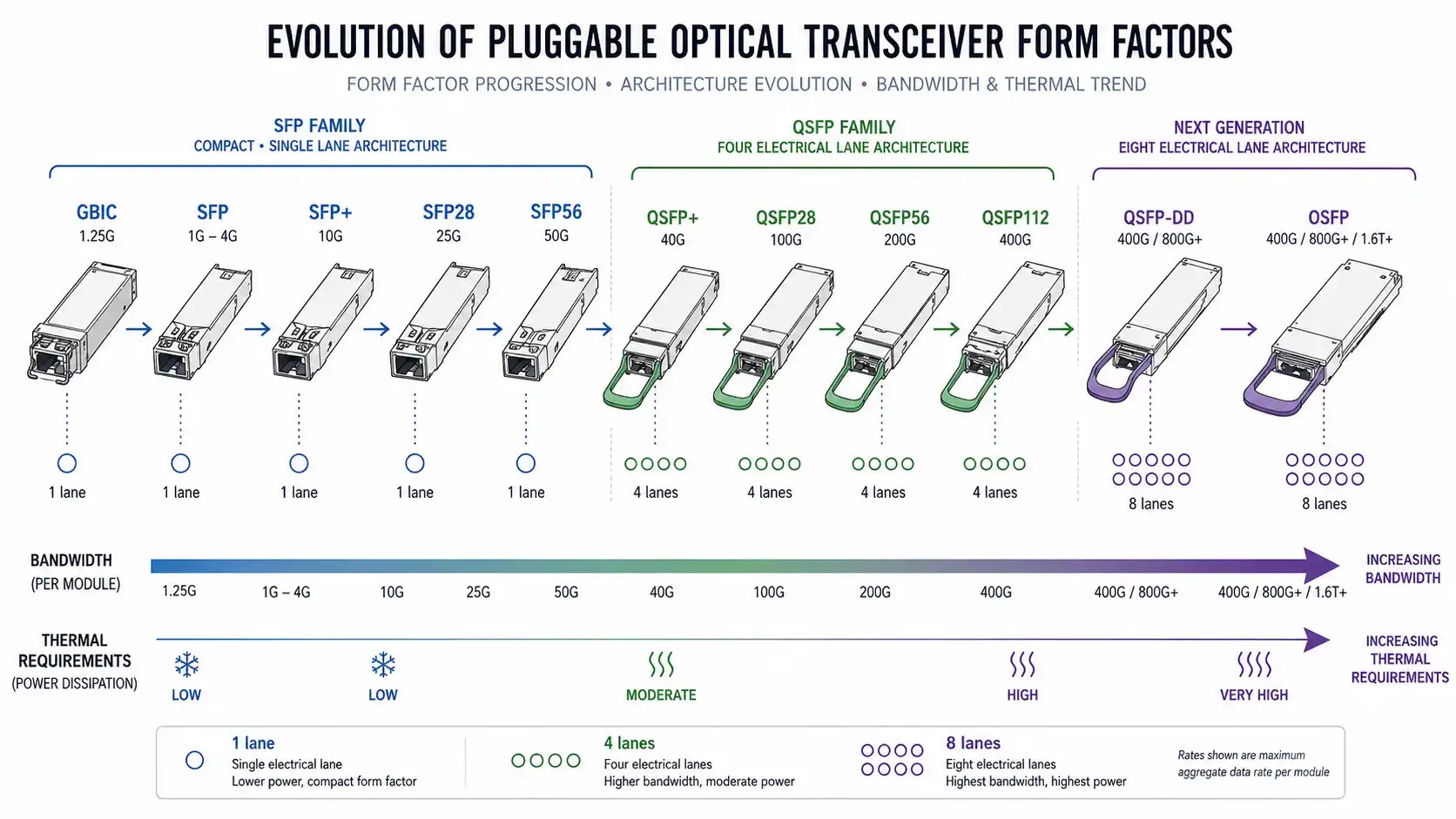
That evolution created a long list of names: SFP, SFP+, SFP28, SFP56, QSFP+, QSFP28, QSFP56, QSFP112, QSFP-DD, OSFP and several newer variants. The names are easier to understand when they are treated as related design families rather than isolated acronyms.
The most important distinction is also the easiest to miss: a transceiver form factor is not the same thing as an Ethernet speed or optical standard. A form factor describes how a module fits and connects to its host. The actual optical link still depends on the transceiver specification, fiber, wavelength, connector, reach and host configuration.
This guide explains how the major optical transceiver form factors evolved, how the SFP and QSFP families differ, where QSFP-DD and OSFP fit, and how to choose a compatible module for a real network. For product-level examples across multiple families, see the fiber optic transceiver range.
What Is an Optical Transceiver Form Factor?
An optical transceiver form factor defines the physical package and host-side interface used by a pluggable module. Depending on the specification, it can define or constrain module dimensions, cage and connector geometry, high-speed electrical lanes, low-speed control signals, management interfaces, power classes and thermal behavior.
Those characteristics matter because they affect how many ports can fit on a switch, what electrical signaling a port can support, how much power a module may consume and whether the host can mechanically and electrically accept a particular module generation.
What a Form Factor Defines
- Module size and mechanical envelope
- Host connector and cage design
- Number and arrangement of high-speed electrical lanes
- Low-speed control and management connections
- Power and thermal design constraints
- Part of the compatibility framework between the module and host
What a Form Factor Does Not Define
A form factor alone does not tell you:
- whether the optical link uses single-mode or multimode fiber;
- whether the front connector is LC, MPO/MTP or another interface;
- the transmission distance;
- the wavelength or wavelength plan;
- whether the module implements SR, DR, FR, LR or another optical specification; or
- whether a specific switch, router or NIC will operate the module.
This separation is reflected in industry documentation. Form-factor specifications focus on the module-to-host interface, while Ethernet physical-layer specifications define the signaling needed for particular network applications. The SNIA SFF specifications, the QSFP-DD MSA specifications and the OSFP MSA specifications are useful primary references for these hardware families.
Optical Transceiver Form Factors at a Glance
The table below gives a family-level overview. The speed column shows common associations, not a rule that a form factor has only one possible data rate.
| Form Factor | Host Electrical Lanes | Common Network Association | Typical Role | Key Design Characteristic |
|---|---|---|---|---|
| SFP | 1 | 1G-class | Enterprise and access | Compact pluggable interface |
| SFP+ | 1 | 10G-class | Servers, switches and telecom | Higher-rate signaling in the SFP footprint |
| SFP28 | 1 | 25G-class | Server and switch links | 25G-class serial host interface |
| SFP56 | 1 | 50G-class | Higher-speed server and access links | Higher per-lane signaling rate |
| SFP-DD | 2 | 100G-class and newer implementations | High-density applications | Double-density SFP electrical interface |
| QSFP+ | 4 | 40G-class | Aggregation and data center switching | Four-lane architecture |
| QSFP28 | 4 | 100G-class | Data center and telecom | High density with breakout options |
| QSFP56 | 4 | 200G-class | High-performance switching | Faster signaling on four lanes |
| QSFP112 | 4 | 400G-class | Newer high-speed platforms | Higher per-lane electrical rate |
| QSFP-DD | 8 | 400G / 800G / 1.6T-class | High-density data centers | Eight lanes in a QSFP-derived design |
| OSFP | 8 | 400G / 800G / 1.6T-class | AI, HPC and large data centers | Eight-lane design with substantial thermal headroom |

Always treat this kind of table as a navigation aid rather than a purchasing specification. The host port, electrical mode, module type, optical standard and software support still need to match.
Why Optical Transceiver Form Factors Keep Changing
The history of pluggable optics is easier to understand as a sequence of engineering problems. The industry has repeatedly tried to put more usable bandwidth into a smaller amount of front-panel space without exceeding practical power, signal-integrity and thermal limits.
Stage 1: Making Pluggable Optics Smaller
Early pluggable interfaces such as GBIC made optical ports replaceable, but the modules occupied substantial front-panel space. The 10G era also produced larger formats such as XENPAK, X2 and XFP. These formats were important stepping stones, but equipment designers increasingly wanted more ports per rack unit.
SFP changed that balance by offering a much smaller pluggable package. The compact footprint became a platform for later generations rather than a one-speed design. That reuse of the basic ecosystem is one reason SFP-family interfaces remained relevant as Ethernet moved through several speed generations.
Stage 2: Increasing Bandwidth Without Abandoning the SFP Footprint
The progression from SFP to SFP+, SFP28 and SFP56 illustrates a recurring design strategy: keep a compact physical ecosystem while increasing the electrical signaling capability of the host interface. The practical result was that 10G, 25G and 50G-class connectivity could be delivered without moving every application to a larger multi-lane module.
This approach is particularly useful for server-facing ports, access networks and other situations where a single serial lane provides the required link bandwidth.
Stage 3: Moving from One Lane to Four
As aggregate bandwidth requirements increased, a second path became more important: using multiple electrical lanes in one pluggable module. QSFP stands for Quad Small Form-factor Pluggable, and the four-lane architecture is the key to understanding the family.
Instead of relying on one lane, the host can combine four lanes for a higher aggregate port rate. The same multi-lane structure also supports breakout architectures when the host, cable or transceiver and software configuration allow the higher-speed port to operate as multiple lower-speed links.
This is why the QSFP family became strongly associated with high-density aggregation and data center switching. The older 40G QSFP range is a useful example of how four lanes became a common building block for higher-bandwidth ports.
Stage 4: Increasing Per-Lane Signaling
Once the four-lane QSFP structure was established, the next major gains came from making each electrical lane faster. QSFP28, QSFP56 and QSFP112 follow this pattern. The physical family remains recognizable, but the host electrical generation changes substantially.
This is an important reason not to infer compatibility from shape alone. A module may fit a familiar cage while still requiring a host electrical mode, firmware configuration or power class that an older port cannot provide.
Stage 5: Doubling Lane Density for 400G, 800G and Beyond
QSFP-DD extends the QSFP concept from four high-speed electrical lanes to eight. The additional lane density allows much more aggregate host bandwidth while preserving a compact front-panel format. The QSFP-DD MSA has published hardware specifications spanning QSFP-DD, QSFP-DD800 and QSFP-DD1600 generations.
The design also places strong emphasis on continuity with the broader QSFP ecosystem. In practice, however, backward compatibility still depends on how the specific switch or system implements its ports. A mechanical fit is not a substitute for the vendor support matrix.
Stage 6: Designing for Higher Power and Thermal Loads
Higher-speed pluggable optics can consume more power and create more heat. This makes thermal design part of the form-factor discussion rather than an afterthought.
OSFP also uses eight high-speed electrical lanes in its standard form, but it uses a larger mechanical envelope than QSFP-DD. That larger package provides more room for cooling and high-power optical implementations. The OSFP MSA describes standard OSFP as an eight-lane interface and publishes separate specifications for OSFP-XD, a higher-density sixteen-lane form factor.
The result is not that one high-speed form factor is universally better. QSFP-DD and OSFP represent different system-level tradeoffs involving density, cooling, ecosystem continuity and switch architecture.
Understanding the SFP Family
The traditional SFP branch is easiest to understand as a compact single-lane family whose electrical signaling capability increased over time. That summary is useful, but it should be limited to the traditional SFP branch because newer double-density designs introduce exceptions.
SFP
SFP stands for Small Form-factor Pluggable. It became widely associated with Gigabit Ethernet and other serial networking applications because it offered a much smaller pluggable package than earlier formats.
SFP remains relevant in installed enterprise, industrial and access networks where 1G-class connectivity is sufficient. The exact module may use different fiber types, wavelengths and reaches, so the host interface is only the first part of the selection process.
SFP+
SFP+ extended the compact SFP concept into the 10G generation. It allowed switches and servers to provide many 10G ports in a small amount of front-panel space and became an important interface across enterprise, telecom and data center networks.
The familiar footprint can make compatibility look simpler than it is. An SFP+ port, SFP28 port and other SFP-family interfaces may be mechanically related, but the supported operating modes must still be confirmed on the exact equipment.
SFP28
SFP28 brought 25G-class signaling to the traditional one-lane SFP architecture. This made it especially useful for server-to-switch connectivity, where 25G offered more bandwidth than 10G without requiring a four-lane QSFP port for every server connection.
For examples of this compact module ecosystem, the SFP transceiver section provides a practical product-level view across common SFP-family applications.
SFP56, SFP112 and Higher-Rate SFP Interfaces
SFP56 continues the same general idea at a higher electrical lane rate and is commonly associated with 50G-class applications. Newer SFP-related specifications extend the ecosystem toward still higher per-lane signaling rates.
The naming progression is useful as a technical clue, but it should not be treated as a universal compatibility promise. Higher-rate interfaces place new requirements on signal integrity, power, host design and firmware support.
SFP-DD: Why "SFP Means One Lane" Is No Longer Always True
SFP-DD, or Small Form-factor Pluggable Double Density, is the important exception to the simple "SFP equals one lane" rule. It adds a second high-speed electrical lane while retaining a compact SFP-width design philosophy.
This makes it possible to increase aggregate host bandwidth and port density without moving every application into a four-lane QSFP package. It also shows why modern form-factor families should be described with scope: traditional SFP generations are single-lane, but the wider SFP ecosystem now includes multi-lane designs.
Understanding the QSFP Family
The QSFP family is built around four high-speed electrical lanes. Unlike the traditional SFP progression, which typically increases the capability of a single lane, QSFP combines four lanes into a compact high-density pluggable interface.
QSFP+
QSFP+ became closely associated with 40G Ethernet. Four-lane operation made it suitable both for an aggregated 40G connection and, where supported, breakout into multiple lower-speed lanes.
This relationship between aggregate bandwidth and breakout capability is one of the most important architectural ideas in the QSFP family. A port is not useful only at the large number printed on its label; the supported lane modes may also make it useful as several smaller logical links.
QSFP28
QSFP28 raised the electrical capability of each of the four QSFP lanes and became a major 100G form factor. It remains important across data center switching, aggregation, telecom and transport applications.
The physical form factor does not tell you whether a 100G module is SR4, CWDM4, LR4, DR or another optical design. For that reason, a 100G QSFP28 transceiver category may contain modules with very different reaches, connectors and fiber requirements.
QSFP56
QSFP56 keeps the four-lane architecture but increases the electrical rate per lane again, making it commonly associated with 200G-class applications. The important change is not a new lane count; it is greater bandwidth per lane.
This pattern is useful for decoding form-factor evolution: sometimes bandwidth rises because the module gains more lanes, and sometimes it rises because the existing lanes become faster.
QSFP112 and QSFP224
QSFP112 and QSFP224 extend the four-lane QSFP family toward higher per-lane signaling rates. SNIA's published SFF-8665 revision 2.0 covers the QSFP28, QSFP56, QSFP112 and QSFP224 generations within the QSFP 4X pluggable transceiver family.
These newer interfaces reinforce the same rule used throughout this guide: the family name explains the host-side architecture, while the actual network rate and optical application still depend on the supported signaling mode and module specification.
SFP vs QSFP: What Is the Real Difference?
SFP and QSFP are often compared as if one is simply a faster version of the other. The more useful distinction is architectural.

| Comparison | Traditional SFP Family | QSFP Family |
|---|---|---|
| Host electrical lanes | Typically 1 | 4 |
| Primary design goal | Compact serial connectivity | Higher aggregate bandwidth and density |
| Common roles | Access, server-facing and enterprise links | Aggregation, leaf/spine and higher-capacity switching |
| Breakout | Less central to the traditional architecture | Common in many supported multi-lane deployments |
| Important exception | SFP-DD adds a second lane | QSFP-DD is a separate double-density eight-lane design |
Electrical Lane Count
Traditional SFP+, SFP28 and similar interfaces use one high-speed electrical lane. QSFP uses four. That four-lane architecture gives the host more aggregate electrical bandwidth without requiring four separate front-panel cages.
Port Density and Aggregate Bandwidth
Port density is not simply a question of module width. It is the amount of useful network bandwidth a system can expose across the front panel while meeting electrical and thermal constraints. QSFP-family interfaces became attractive because multiple lanes can be presented through one compact port.
Breakout Capability
Many QSFP-family systems can operate one higher-speed physical port as several lower-speed links. A common example is a higher-bandwidth switch port connected to a breakout cable or breakout optical design. The exact mode depends on the switch ASIC, port configuration, cable or transceiver and software support.
Typical Deployment Scenarios
SFP-family interfaces are often a natural choice for compact serial links to servers, access switches and installed enterprise equipment. QSFP-family interfaces are common where aggregation bandwidth, breakout flexibility and front-panel density are more important.
Neither family should be selected only by its acronym. Start with the host port and topology, then choose the compatible optical implementation.
QSFP-DD vs OSFP: Two Approaches to High-Speed Pluggable Optics
At 400G, 800G and higher rates, QSFP-DD and OSFP are two of the most important pluggable form factors. Both can support very high aggregate bandwidth, but they approach mechanical density and thermal design differently.

What QSFP-DD and OSFP Have in Common
- Both standard designs use eight high-speed host electrical lanes.
- Both are used in high-capacity data center platforms.
- Both support generations associated with 400G, 800G and 1.6T-class interfaces.
- Both require careful attention to module power, airflow and platform support.
- Neither defines one specific optical reach or front connector.
Where Their Designs Differ
QSFP-DD extends the established QSFP mechanical ecosystem with an additional row of electrical contacts. One of its design goals is to preserve density and allow systems to maintain continuity with QSFP-family modules when the host implementation supports that use case.
OSFP uses a larger mechanical envelope. The standard form factor includes an integrated heatsink approach, and the larger package can provide useful thermal headroom for high-power optics. That tradeoff can be attractive in high-performance data center, AI and HPC platforms where cooling is a primary system constraint.
Which One Should You Choose?
Start with the networking platform, not a generic form-factor ranking.
If the switch exposes QSFP-DD ports, the practical module universe begins with the QSFP-DD and supported QSFP ecosystem for that specific platform. If the switch is designed around OSFP, OSFP modules become the natural starting point.
After port compatibility, compare the required network rate, module power, cooling design, fiber infrastructure, connector strategy, breakout requirements, reach and availability of the optical specification you need. In other words, choose the network architecture first and the compatible transceiver second.
Which Form Factor Is Used for 1G, 10G, 25G, 100G, 400G and 800G?
Users often approach the problem from the opposite direction: they know the link speed they need and want to know which form factor is common. The table below provides a practical starting point.
| Network Speed | Common Form Factors | Important Note |
|---|---|---|
| 1G | SFP | Common in enterprise and access networks. |
| 10G | SFP+, XFP | SFP+ is common in higher-density equipment; XFP remains in older systems. |
| 25G | SFP28 | Common for server and switch links. |
| 40G | QSFP+ | Often associated with four-lane aggregation and breakout. |
| 50G | SFP56 and other supported implementations | Actual form factor depends on the host architecture. |
| 100G | QSFP28, CFP-family and selected newer interfaces | QSFP28 is common, but the optical standard still determines fiber and reach. |
| 200G | QSFP56, QSFP-DD and other platform-specific implementations | Check the required electrical and breakout mode. |
| 400G | QSFP-DD, OSFP, QSFP112 and other supported designs | The switch port and optical specification determine the correct module. |
| 800G | QSFP-DD800, OSFP and newer high-speed platforms | Power, thermals and lane rate become especially important. |
| 1.6T | QSFP-DD1600, OSFP-class and other next-generation implementations | Use the exact host and module specifications rather than a generic family assumption. |
Speed alone does not determine the form factor. Multiple physical interfaces can exist for the same Ethernet generation, and one form-factor family can span several network rates.
Connector Type Is Not the Same as Form Factor
Another common source of confusion is mixing the host-side form factor with the front optical connector. They describe different parts of the module.
LC Duplex
LC duplex is common in many serial or wavelength-multiplexed optical links. It may appear on modules from different form-factor families, so seeing an LC connector does not identify the host interface by itself.
MPO/MTP
Parallel-optics and breakout applications often use MPO/MTP connectivity because multiple fibers can be presented in one compact connector. High-density cabling design can therefore become an important part of selecting QSFP-family and other multi-lane optics. The MTP/MPO cable assembly section provides examples of trunk, harness and fanout configurations used in these architectures.
Why the Same Form Factor Can Use Different Connectors
The optical engine inside a module determines how many fibers or wavelengths are required. One QSFP-family module may use parallel fibers through MPO/MTP, while another may multiplex wavelengths and use duplex LC. Both can share the same host form factor.
When evaluating a design, check the module data sheet and the existing fiber plant rather than assuming the connector from the form-factor name. For broader connector options, see the fiber optic connector category.
How to Choose the Right Optical Transceiver Form Factor
A reliable selection process starts with the network architecture, not with a list of module acronyms.

1. Start With the Host Port
Identify the exact switch, router, NIC or transport platform and the port type it provides. Check the equipment documentation for supported form factors, module generations and port operating modes.
A module that fits mechanically may still fail because the host does not support its electrical signaling, power class, management interface, coding or software requirements.
2. Confirm the Required Speed and Port Mode
Determine whether the link will operate as a native connection or a breakout configuration. A 400G physical port, for example, may be intended for one 400G link, four 100G links, two 200G links or another mode depending on the platform.
This step can eliminate many apparently compatible modules before fiber and reach are even considered.
3. Choose the Optical Standard, Fiber Type and Reach
Next identify the link requirement itself:
- single-mode or multimode fiber;
- required transmission distance;
- parallel or wavelength-multiplexed optics;
- SR, DR, FR, LR or another optical specification;
- wavelength requirements; and
- existing fiber infrastructure.
The optical standard becomes more important than the form factor at this stage. Two modules in the same cage can be designed for completely different links.
If the architecture uses wavelength multiplexing, compatible CWDM or DWDM components may also become part of the system design rather than a property of the form factor itself.
4. Check Connector and Breakout Requirements
Confirm whether the fiber plant uses duplex or parallel cabling and whether the intended port mode needs a breakout cable, fanout harness or breakout optical module.
Do not assume that a high-speed port supports every theoretically possible split. The host ASIC, firmware, module and cabling must all support the same lane mapping.
5. Check Power and Thermal Limits
High-speed optics can draw substantially more power than earlier short-reach modules. Check the host's supported module power class, airflow direction, ambient temperature limits and cage cooling design.
This step is especially important for dense 400G, 800G, 1.6T and coherent optical modules, where a mechanically compatible module may still exceed the platform's thermal or electrical budget.
6. Verify Device, Firmware and Vendor Compatibility
Before purchasing, confirm the exact equipment model and software version. Check:
- supported transceiver types;
- approved port modes;
- firmware requirements;
- module coding or EEPROM restrictions;
- breakout support;
- power class;
- operating temperature; and
- any vendor-specific limitations.
Form-factor compatibility is only one layer of interoperability. Operational compatibility requires the host, module, optical link and software environment to agree.
Example: Choosing a Form Factor for a 400G Link
Consider a new 400G connection between two data center switches. A useful decision process looks like this:
- Identify the switch ports. Determine whether the platform provides QSFP-DD, OSFP, QSFP112 or another 400G-capable port type.
- Confirm the port mode. Decide whether each port will remain one 400G link or break out into lower-speed connections.
- Select the optical application. Choose the required 400G optical standard based on reach and topology.
- Match the fiber plant. Confirm single-mode or multimode fiber and whether the existing cabling supports the chosen optical design.
- Confirm the connector. Determine whether the module requires duplex LC, MPO/MTP or another interface.
- Check power and cooling. Verify that the host can support the module power class under the expected airflow and ambient conditions.
- Validate vendor support. Confirm the exact transceiver, switch model, firmware and breakout configuration in the vendor compatibility documentation.
Notice that the process does not begin with "Which 400G transceiver should I buy?" It begins with the host architecture. The form factor is determined by the equipment before the optical reach and connector are finalized.
Legacy Form Factors You May Still Encounter
Older networks can contain form factors that are no longer the default choice for new high-density designs. They still matter during upgrades, migrations and maintenance.
GBIC
GBIC, or Gigabit Interface Converter, was an early hot-pluggable transceiver format. Its major contribution was replaceability, but its physical size limited front-panel density compared with the SFP interfaces that followed.
XENPAK, X2 and XFP
The early 10G transition produced several larger module formats. XENPAK and X2 represented early high-speed pluggable approaches, while XFP provided a smaller serial 10G form factor. These interfaces can still appear in older transport and networking equipment.
CFP, CFP2 and CFP4
The CFP family became important during the early development of 100G systems and later evolved into smaller CFP2 and CFP4 packages. CFP-family modules remain relevant in certain telecom, coherent and installed-platform applications, but high-density Ethernet switching increasingly moved toward QSFP-family designs.
The practical lesson is simple: legacy form factors matter when they are already present in the equipment, but they should not automatically determine the architecture of a new network.
Where Optical Transceiver Form Factors Are Going Next
The underlying direction remains consistent even as the names change: more electrical bandwidth per port, higher front-panel density and tighter attention to signal integrity, module power and cooling.
Higher Electrical Lane Rates
One path to greater bandwidth is to make each host electrical lane faster. This is visible in the progression from SFP28 to SFP56 and newer SFP interfaces, and from QSFP28 to QSFP56, QSFP112 and QSFP224.
Higher per-lane rates can preserve familiar lane counts while increasing aggregate port bandwidth, but they also raise electrical design requirements for the connector, cage, PCB and host silicon.
Higher Lane Counts
Another path is to increase the number of electrical lanes. SFP-DD moves from the traditional one-lane SFP model to two lanes. QSFP-DD doubles the four-lane QSFP architecture to eight. OSFP-XD extends the idea further with sixteen high-speed electrical lanes in a separate form factor.
These examples show why short rules such as "SFP is one lane" or "OSFP is eight lanes" need context. They describe specific branches, not every future interface carrying a related name.
Coherent Pluggable Optics
Coherent technology is increasingly available in pluggable modules for metro, data center interconnect and other longer-reach applications. Coherent is an optical transmission technology, not a form factor. A coherent module still needs a host mechanical and electrical interface such as a supported QSFP-family, OSFP or other platform.
AI and HPC Increase the Pressure on Density and Thermals
AI and high-performance computing clusters place unusually heavy demands on network bandwidth. As switch capacity rises, module power and cooling become system-level constraints alongside port count.
This is one reason form-factor design now involves much more than making a module physically smaller. A useful high-speed form factor has to balance electrical bandwidth, optical power, heat removal, serviceability and front-panel density.
Common Mistakes When Comparing Transceiver Form Factors
Mistake 1: Treating Form Factor as an Ethernet Standard
A QSFP or SFP name does not fully define the Ethernet optical application. Always identify the actual optical specification, fiber type, reach and wavelength requirements.
Mistake 2: Assuming Similar Mechanical Size Means Compatibility
Related module generations may share a physical ecosystem, but the host can still reject or fail to operate a module because of electrical signaling, firmware, power or coding differences.
Mistake 3: Choosing by Speed Alone
Two modules marketed for the same aggregate Ethernet rate may use different form factors, optical technologies, lane arrangements, connectors and fiber architectures. The correct choice depends on the complete system design.
Mistake 4: Ignoring Breakout Architecture
Breakout is a host capability as much as a cable or transceiver feature. Confirm the required lane mapping before choosing the optics and cabling.
Mistake 5: Ignoring Power and Thermal Limits
A module can fit the port but still exceed the host's supported power class or cooling capability. This becomes increasingly important as networks move toward higher-capacity pluggable optics.
Frequently Asked Questions
What is the difference between SFP and QSFP?
The most useful architectural difference is lane count. Traditional SFP-family interfaces such as SFP+, SFP28 and SFP56 use one high-speed host electrical lane, while QSFP uses four. The wider SFP ecosystem includes exceptions such as two-lane SFP-DD.
Is QSFP28 the same as QSFP+?
No. They belong to the same broader four-lane QSFP family, but they represent different electrical generations and are commonly associated with different network rates. Host support should be verified before substituting one generation for another.
Can a QSFP-DD port use QSFP28 modules?
Backward compatibility with the broader QSFP ecosystem is a major design goal of QSFP-DD. However, actual operation depends on the system implementation, port mode, software and equipment vendor support. Do not assume that every QSFP28 module will operate in every QSFP-DD port.
What form factor is commonly used for 100G?
QSFP28 is one of the most common 100G form factors. Other implementations also exist, especially in older, telecom or specialized platforms. The correct module still depends on the host port and optical link specification.
What form factors are commonly used for 400G?
QSFP-DD and OSFP are important 400G form factors, and QSFP112 is used in newer four-lane electrical architectures. The switch port determines which family can be used.
What form factors are commonly used for 800G?
OSFP and QSFP-DD800 are important high-density 800G options. Other architectures also exist, and the correct choice depends on the switch, lane rate, optical standard, connector, power and cooling design.
Is OSFP better than QSFP-DD?
Not universally. OSFP provides a larger mechanical envelope and strong thermal headroom, while QSFP-DD emphasizes compact density and continuity with the QSFP ecosystem. The better choice is the form factor supported by the network platform and optical application.
Does form factor determine whether the connector is LC or MPO/MTP?
No. The same form-factor family can contain modules with different optical connector types. Connector choice depends on the optical design, fiber count and link architecture.
Does transceiver form factor determine transmission distance?
No. Reach is determined by the optical specification and link design, including fiber type, wavelength, modulation and optical power budget. Form factor defines the host-side package, not the transmission distance.