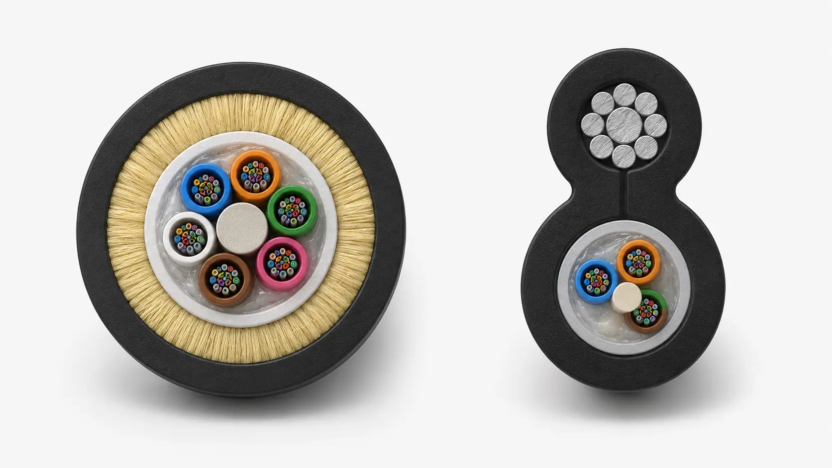
Picture a hyperscale data center facility in Northern Virginia processing 40 terabits of traffic per second. Behind those seamless cloud services and split-second data transfers lies a critical infrastructure component most people never see: thousands of MTP fiber optic connectors enabling 12 or more fiber strands to connect through a single interface no larger than a standard USB port. These multi-fiber connectors have transformed how modern networks handle bandwidth demands, particularly as AI workloads and 5G deployments push data centers toward unprecedented density requirements. Understanding how MTP fiber optic connectors work reveals why this technology now dominates high-performance networking environments where space constraints meet explosive bandwidth growth.

The Data Center Connectivity Challenge Driving MTP Adoption
The global data center optical fiber market reached $15 billion in 2025 and analysts project growth to $40 billion by 2033, reflecting fundamental shifts in how enterprises architect their network infrastructure. Between 2020 and 2024, bandwidth purchases for data center connectivity surged by 330%, with hyperscale operators accounting for 57% of metro dark fiber installations during this period.
These numbers tell a story of infrastructure under pressure. When Gartner surveyed network architects in late 2024, respondents cited cable management as their second-highest operational challenge after power availability. Traditional duplex connectors-handling just two fibers per termination-create cable congestion that impedes airflow, complicates maintenance, and ultimately limits rack density. A typical 42U rack using conventional LC connectors might accommodate 144 fiber connections across six panels. The equivalent MTP-based system consolidates those same 144 fibers into just 12 connector positions.
This density advantage extends beyond simple space savings. Data centers now deploy AI training clusters requiring all-to-all GPU interconnectivity at bandwidths exceeding 400 Gbps per link. Meeting these requirements with duplex connectors would demand rack space that simply doesn't exist in high-value colocation facilities. MTP fiber optic connectors solve this problem by enabling parallel optics architectures where multiple fiber pairs transmit simultaneously through standardized interfaces.
The technology addresses three converging infrastructure demands that define modern networking: exponential bandwidth growth, physical space constraints, and operational complexity reduction. As data centers evolve from 100G to 400G and beyond, MTP connectivity provides the physical layer foundation that makes these transitions feasible without completely redesigning structured cabling systems.
What is an MTP Fiber Optic Connector?
An MTP fiber connector is a high-performance multi-fiber termination developed by US Conec that houses between 8 and 144 individual fiber strands within a single compact connector body. The technology builds upon the earlier MPO (Multi-Fiber Push-On) standard established by NTT in Japan during the 1980s, but incorporates critical design enhancements that improve both optical performance and mechanical durability.
The relationship between MPO and MTP often causes confusion in the industry. Think of MTP as an enhanced, trademarked version of the generic MPO connector format. Both comply with IEC-61754-7 and TIA-604-5 international standards, ensuring backward compatibility and interoperability. However, MTP connectors feature proprietary improvements including metal pin clamps instead of plastic, elliptical guide pins rather than flat-ended pins, and a removable housing design that enables field repairs.
While standard MPO connectors typically handle 500 mating cycles before degradation, MTP fiber optic connectors sustain over 1,000 connections with insertion loss changes under 0.2dB. This durability matters significantly in dynamic data center environments where technicians frequently reconfigure connections to accommodate workload migrations and infrastructure upgrades.
The physical footprint provides another key advantage. An MTP connector's dimensions approximate those of a standard duplex LC or SC connector, yet it accommodates six times the fiber count. In practical terms, a single 1U patch panel equipped with MTP connectors holds 864 fibers-the equivalent of six conventional panels requiring 6U of valuable rack space. This density transformation explains why hyperscale operators have standardized on MTP connectivity for backbone infrastructure serving hundreds of thousands of servers.
From an architectural perspective, MTP connectors serve as the critical interface point between pre-terminated trunk cables and modular cassette systems. This plug-and-play approach reduces installation time by up to 75% compared to traditional field-termination methods, while simultaneously improving optical performance through factory-polished connectors that eliminate the variability inherent in field polishing operations.
The Physical Mechanics: How MTP Fiber Optic Connectors Achieve Precision Alignment
The operational principle behind MTP fiber optic connectors centers on precise mechanical alignment of multiple fiber cores, each measuring just 9 microns in diameter for single-mode fiber or 50-62.5 microns for multimode applications. This alignment occurs through a sophisticated interplay of components designed to tolerances measured in micrometers.
At the core sits the MT ferrule-a rectangular precision component manufactured from glass-filled thermoplastic polymer. This ferrule houses the individual fiber strands in a linear array, with each fiber terminating flush with the ferrule's polished endface. The ferrule's dimensions measure approximately 6.4mm wide by 2.5mm thick, with fiber positions arranged along its length at precisely 250-micron intervals. For a 12-fiber connector, this creates a fiber span of just 2.75mm across the ferrule face.
Alignment between mating connectors relies on two precision guide pins, typically 700 microns in diameter, manufactured from hardened stainless steel. These pins insert into corresponding guide pin holes positioned on either side of the fiber array. In the mating process, the male connector (equipped with guide pins) inserts into the female connector (featuring guide pin holes), and the pins guide the two ferrules into alignment with sub-micron precision.
The genius of the MTP design lies in its elliptical pin geometry. Unlike earlier MPO connectors that employed flat-ended pins, MTP guide pins feature carefully engineered elliptical tips that reduce insertion force while minimizing wear during repeated mating cycles. This seemingly minor design change reduces debris generation by approximately 60% and extends connector lifespan substantially.
Behind the ferrule, a spring mechanism provides the constant force necessary to maintain physical contact between mated connectors. This spring pushes the ferrule forward within its housing, ensuring that when two connectors mate, their endfaces press together with controlled, consistent pressure-typically around 7-10 Newtons of force. This physical contact proves critical because even microscopic air gaps between fiber endfaces cause signal loss through Fresnel reflection.
The MTP's floating ferrule design represents another crucial innovation. Rather than rigidly fixing the ferrule to the connector housing, the design allows approximately 1mm of lateral movement. This floating mechanism enables the ferrules to self-align and maintain contact even when connectors experience minor lateral stress from cable movement or vibration. In earlier MPO designs, any lateral force on the cable housing could break physical contact between ferrules, causing signal degradation or complete link failure.
A push-pull latch mechanism completes the assembly, providing the retention force that keeps connectors seated in their adapter or equipment interface. The latch design allows one-handed operation while ensuring secure connections that resist accidental disconnection from cable weight or routine handling.
Polarity Management: The Critical Design Consideration
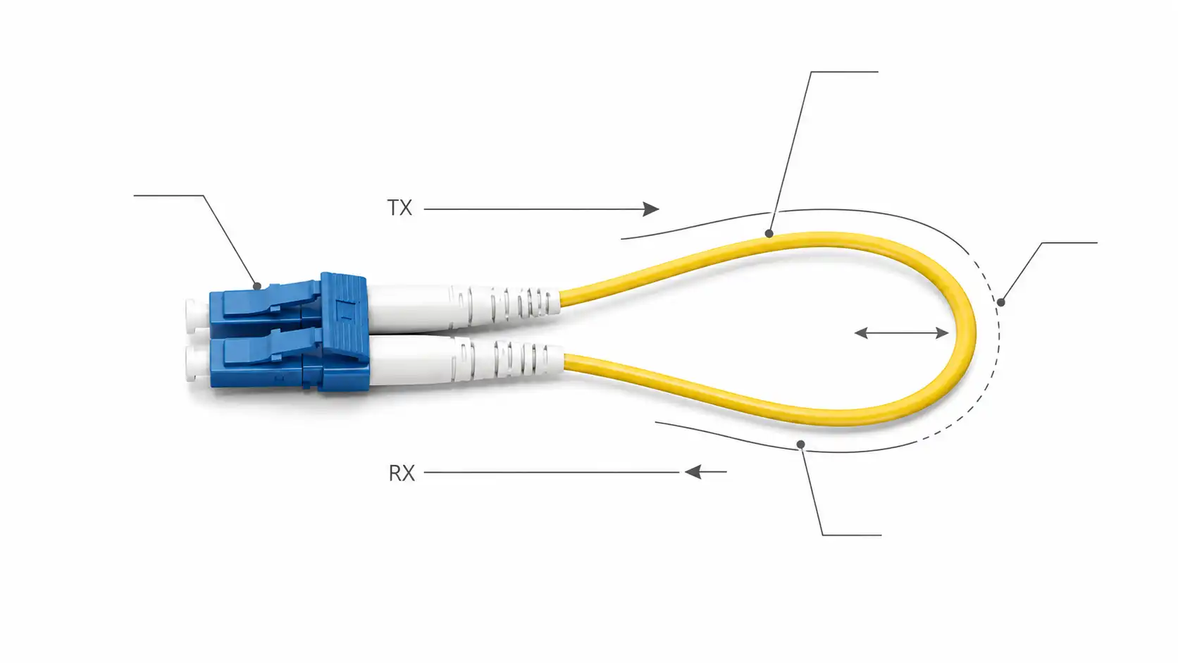
Polarity management represents perhaps the most technically challenging aspect of MTP system design. The term "polarity" refers to ensuring that each transmit fiber at one end of a link correctly maps to its corresponding receive fiber at the opposite end. Getting this wrong results in complete link failure, with transmit signals routing to inappropriate destinations.
The challenge emerges from MTP's multi-fiber nature. In traditional duplex connectivity, swapping the two fibers naturally creates the transmit-to-receive crossover. With 12 fibers in a single connector, the crossover becomes substantially more complex. Industry standards define three primary polarity methods-designated Type A, Type B, and Type C-each employing different strategies to achieve proper transmit-receive mapping.
Type A (Method A) cables feature a straight-through configuration where fiber position 1 at one end connects to position 1 at the opposite end. To establish correct polarity, one connector has its key oriented up while the other orients key down. This creates a physical flip when the cable routes through adapters. Type A systems require different patch cord types at each end of the channel: a standard A-to-B patch cord on one side and a crossover A-to-A patch cord on the other.
Type B (Method B) cables employ a reversed fiber sequence. Position 1 at one end connects to position 12 at the opposite end, position 2 to 11, and so forth. Both connectors maintain key-up orientation. This reversal method proves particularly advantageous because it enables using identical A-to-B patch cords at both channel ends. For this reason, Type B has emerged as the preferred polarity method for 40G, 100G, and 400G parallel optics deployments. When a network architect standardizes on Type B, technicians no longer need to differentiate between patch cord types during installation or moves, reducing configuration errors significantly.
Type C (Method C) cables flip adjacent fiber pairs. Position 1 connects to position 2 at the far end, position 2 to 1, position 3 to 4, and so on. This pairs-flipped approach works well for duplex breakout applications where a single 12-fiber MTP trunk fans out to six duplex LC connections. However, Type C proves less suitable for parallel optics applications due to the complex mapping required for 4-lane or 8-lane transceiver interfaces.
Real-world polarity errors occur frequently, particularly in mixed environments or during infrastructure expansions. A mid-sized financial services firm in Chicago learned this painfully when technicians installing new 100G links inadvertently mixed Type A and Type B patch cords, resulting in 16 hours of downtime across trading platforms. The incident highlighted why disciplined polarity management and clear labeling schemes matter critically in MTP deployments.
Industry best practice suggests standardizing on Type B polarity for new deployments while maintaining meticulous documentation of any legacy Type A infrastructure. Some organizations color-code patch cords by polarity type, while others implement rigid procedural controls requiring two-person verification before any production changes. For organizations managing thousands of MTP connections, investing in automated polarity testing equipment pays dividends by catching configuration errors before they impact operations.
MTP Connector Component Anatomy and Materials Science
Understanding MTP performance requires examining the materials science and precision manufacturing behind each component. The MT ferrule's composition-glass-filled thermoplastic-was specifically chosen for its dimensional stability across temperature ranges, low coefficient of thermal expansion, and ability to accept precise molding tolerances. The glass filler content, typically 30-40% by weight, provides the rigidity necessary for maintaining fiber position accuracy while resisting wear from repeated insertions.
The guide pins undergo extensive heat treatment to achieve Rockwell C hardness ratings exceeding 50, making them resistant to deformation even after thousands of mating cycles. Their surface finish specifications call for roughness values below 0.4 micrometers Ra, minimizing friction during insertion while preventing micro-scratches on the guide pin holes that could compromise alignment over time.
Spring selection involves balancing competing requirements. The spring must provide sufficient force to maintain physical contact between ferrules but not so much force that insertion becomes difficult or that the spring's compression permanently deforms the ferrule. MTP designs typically employ precision wave springs manufactured from beryllium copper or stainless steel, selected for their consistent force curves and resistance to stress relaxation.
The connector housing material varies by application. Standard MTP connectors employ high-impact thermoplastic, while ruggedized versions for military or outdoor deployments may incorporate metal housings with environmental sealing. The push-pull latch, typically molded as part of the housing or attached through ultrasonic welding, must withstand at least 1,000 insertion cycles while maintaining adequate pull force-typically specified at 20-40 Newtons minimum.
Endface geometry represents another critical specification. The ferrule endface undergoes precision polishing to create either a physical contact (PC) surface for multimode applications or an ultra-physical contact (UPC) or angled physical contact (APC) surface for single-mode deployments. PC polishing produces a slightly domed endface with a 10-25mm radius of curvature, while APC polishing adds an 8-degree angle that directs back-reflections away from the fiber core. The polishing process must achieve surface roughness below 0.5 micrometers and apex offset (the deviation of the fiber's highest point from the ferrule's geometric center) under 50 nanometers for optimal performance.
Quality control during manufacturing employs automated interferometry to verify endface geometry, ensuring each connector meets specifications before shipping. Premium MTP Elite connectors undergo additional testing including return loss measurements and insertion loss validation, with manufacturers typically guaranteeing maximum insertion loss of 0.35dB for multimode and 0.5dB for single-mode applications.

Installation Process and Field Considerations
Deploying MTP fiber optic connectors differs substantially from traditional duplex fiber installation, requiring technicians to understand both the mechanical assembly process and the critical inspection procedures that ensure long-term reliability.
The installation sequence begins with proper cable preparation. Pre-terminated MTP trunk cables arrive from the factory with connectors already attached and tested, eliminating field polishing. However, technicians must handle these cables carefully during installation to avoid damaging the precision-polished endfaces. Most manufacturers provide dust caps that must remain in place until immediately before mating connections.
Before making any connection, visual inspection through a fiber microscope proves essential. Research indicates that contamination causes approximately 80% of network problems in fiber optic systems. A single dust particle on an MTP connector endface-each fiber core measuring just 9 microns for single-mode applications-can cause complete signal loss or damage the fiber during mating. The inspection process examines each fiber position individually, looking for contamination, scratches, or epoxy overflow that might compromise the connection.
Cleaning procedures for MTP connectors employ specialized tools. Unlike duplex connectors that can be cleaned with simple wipes, MTP connectors require cassette-style cleaners that simultaneously clean all fiber positions in a single action. These cleaners use microfiber material specifically designed to remove contaminants without leaving residue. The cleaning process should occur immediately before mating, as environmental exposure can re-contaminate connectors within minutes in dusty data center environments.
The physical mating process demands careful attention to orientation. Each MTP connector features a key-a raised tab on the connector housing-that must align with the adapter or equipment interface. The key ensures proper polarity by preventing insertion in the wrong orientation. Technicians insert the connector straight into the adapter or interface, avoiding any angling that might damage the precision guide pins. The push-pull latch should click audibly when fully seated, providing tactile confirmation of complete insertion.
After making connections, proper testing validates both optical performance and polarity correctness. Basic testing employs a light source and power meter, measuring insertion loss at each wavelength the system will operate. Industry standards specify maximum allowable insertion loss of 0.5-0.75dB per MTP connection depending on fiber type and grade. More sophisticated testing using an OTDR (Optical Time Domain Reflectometer) reveals the exact location and magnitude of any reflective events, helping diagnose problems like contamination or damaged connectors.
Polarity testing deserves special attention given its critical importance. Several manufacturers offer specialized MTP polarity testers that illuminate fibers at one end while verifying which positions light appears at the far end. This testing should occur before energizing any production traffic, as discovering polarity errors during commissioning costs far less than diagnosing them during an outage.
A regional cloud service provider based in Dallas implemented these rigorous procedures after experiencing multiple outages from contaminated connectors. Their revised protocol mandates microscope inspection and cleaning for every connection, even those made with brand-new connectors straight from the manufacturer. Since implementing this policy, their MTP-related trouble tickets decreased by 73%, validating the investment in proper procedures and inspection equipment.
Performance Characteristics and Loss Budget Analysis
MTP connector performance characteristics directly impact network design and troubleshooting. Understanding the optical physics behind these specifications enables better decision-making during system design and helps diagnose problems when they arise.
Insertion loss-the amount of signal power lost when light passes through a connection-represents the primary performance metric. For MTP connectors, insertion loss arises from several mechanisms. Lateral offset, where fiber cores don't align perfectly, causes light to miss the receiving fiber core partially. Angular misalignment, where one fiber's axis doesn't parallel the mating fiber, similarly reduces coupling efficiency. Endface gaps, even microscopic air spaces between mated connectors, cause Fresnel reflection that removes power from the transmitted signal.
Industry specifications for MTP connectors typically cite maximum insertion loss of 0.35dB for multimode connections and 0.5dB for single-mode. However, well-manufactured connectors routinely achieve performance below 0.25dB. MTP Elite connectors, featuring even tighter manufacturing tolerances, often measure under 0.15dB insertion loss, rivaling the performance of premium simplex connectors.
Return loss quantifies how much optical power reflects back toward the source, expressed as a negative number in decibels. Higher return loss (more negative values) indicates better performance. MTP connectors with UPC endfaces typically achieve return loss better than -50dB for single-mode applications, while APC connectors exceed -65dB by directing reflections away from the fiber core through their angled endface geometry.
Environmental stability matters particularly in industrial or outdoor deployments. Temperature cycling from -40°C to +70°C can affect insertion loss as materials expand and contract. High-quality MTP connectors maintain insertion loss variation below 0.2dB across this temperature range through careful materials selection and design. Vibration resistance proves equally important, with MTP's floating ferrule design enabling the connector to maintain physical contact even under sustained 10G vibration exposure common in transportation or industrial automation applications.
A manufacturing automation company in the Midwest deployed MTP connectivity throughout their factory floor, connecting programmable logic controllers and machine vision systems. Initial installations using standard-grade connectors experienced intermittent failures during high-vibration conditions. Upgrading to industrial-rated MTP connectors with reinforced housings and enhanced strain relief resolved these issues, demonstrating how application-specific connector selection impacts reliability.
The cumulative loss budget for a complete channel includes not just MTP connectors but also fiber attenuation, splice losses, and any intermediate connections. For a 300-meter 40GBASE-SR4 link using OM4 multimode fiber, the loss budget might allocate 0.9dB for fiber attenuation (3dB/km × 0.3km), 0.75dB total for two MTP connections, and 0.35dB margin for aging and repair, totaling 2.0dB against the interface's 7.3dB loss budget. This conservative planning ensures reliable operation throughout the system's lifetime even as connectors accumulate dust or endfaces experience minor degradation.
Common Implementation Scenarios and Best Practices
Real-world MTP deployments vary significantly based on application requirements, but several common scenarios have emerged as best practices across the industry.
Spine-leaf data center fabrics represent perhaps the most prevalent MTP fiber optic connector use case. In this architecture, leaf switches connect to top-of-rack switches via MTP trunk cables, typically carrying 8 or 12 fibers that fan out to individual server connections through cassette modules. A typical hyperscale deployment might employ 24-fiber MTP trunks connecting spine switches in a centralized distribution area to leaf switches distributed across hundreds of racks. This architecture provides the scalability necessary for supporting mixed workloads from traditional enterprise applications to AI training clusters requiring massive east-west bandwidth.
Storage area network deployments increasingly adopt MTP connectivity to handle the enormous bandwidth requirements of all-flash storage arrays and NVMe over Fabrics protocols. A Fortune 500 financial services firm recently consolidated six separate SAN fabrics into a unified 32Gb Fibre Channel infrastructure using MTP trunks to interconnect director-class switches. The project eliminated 2,400 individual duplex cables, improving airflow to the point where they could decommission four computer room air conditioning units, generating both capital and operational savings.
Campus backbone applications leverage MTP's density advantages in multi-building environments. A university in Texas deployed 144-fiber MTP trunks connecting its data center to eight academic buildings across campus. Rather than pulling twelve separate 12-fiber cables through shared conduit-requiring multiple pulls and significantly more labor-the installation used a single 144-fiber MTP cable that terminated in the data center to a high-density enclosure with 12 MTP ports. This approach reduced installation time from the original six-week estimate to just 11 days while providing substantial capacity for future growth.
Edge computing deployments present unique challenges that MTP connectivity addresses effectively. These distributed sites typically feature space-constrained equipment closets where traditional patching would be impractical. Pre-terminated MTP systems enable rapid deployment with minimal on-site labor, critical when rolling out hundreds of edge locations. A retail chain upgrading 800 stores to support real-time inventory tracking and loss prevention deployed pre-configured equipment racks with MTP connectivity pre-installed. Store personnel simply connected pre-terminated MTP trunk cables during installation, eliminating the need for skilled fiber technicians at each location.
Regardless of application, several best practices enhance MTP deployment success. Documentation proves essential-recording polarity types, connector genders, and fiber assignments prevents confusion during troubleshooting and future modifications. Many organizations maintain both electronic databases and physical labels using standardized color-coding schemes. Staged rollouts, where one rack or small equipment cluster validates procedures before wide-scale deployment, catch design issues early when they're inexpensive to correct. Regular inspection and cleaning schedules, preferably documented through quality management systems, maintain optical performance and prevent gradual degradation.
Troubleshooting MTP Connectivity Issues
Despite careful installation, MTP fiber optic connector systems occasionally develop problems requiring systematic diagnosis. Understanding common failure modes accelerates resolution and prevents recurring issues.
Contamination remains the most frequent culprit. Unlike duplex connectors where a technician can visually inspect the single fiber position, MTP connectors hide their 12-24 fiber endfaces within the adapter or interface, making casual inspection impossible. Symptoms typically include intermittent errors, degraded link speeds, or complete link failure. The diagnostic approach begins with fiber microscopy, examining each position individually for dust, oils, or physical damage. Even connectors stored in supposedly clean environments can accumulate contamination, particularly in data centers with raised-floor plenums that circulate unconditioned air. The solution involves proper cleaning using cassette-style cleaners followed by re-inspection before re-mating.
Polarity errors manifest as links that remain dark despite clean connectors and proper seating. Verification requires either a fiber identifier that can detect active traffic and indicate its direction, or systematic testing with light sources to trace fiber paths. Many technicians develop troubleshooting procedures that begin by verifying polarity against documentation, then physical inspection of key orientation and connector types. Discovering a Type A patch cord where documentation specifies Type B immediately identifies the problem source.
Physical damage, while less common, occurs through improper handling or poor storage practices. Guide pins can bend if technicians angle connectors during insertion or apply lateral force on seated connectors. Ferrule endfaces can crack from dropping connectors or excessive cleaning pressure. In some cases, the floating ferrule mechanism can jam from foreign object debris or manufacturing defects. These issues typically require connector replacement, though some organizations maintain field repair capabilities for re-polishing minor endface damage.
Intermittent failures prove particularly challenging to diagnose. Temperature cycling, vibration, or gradual contamination accumulation can cause links to fail unpredictably. Advanced troubleshooting employs continuous monitoring through network management systems combined with environmental sensors tracking temperature and humidity. One data center operator discovered that MTP connection failures correlated with specific air conditioning units cycling on, causing temperature changes that exceeded the building's specification. Addressing the HVAC issue resolved what initially appeared as random fiber failures.
A mid-sized SaaS company experienced mysterious 40G link failures affecting approximately 5% of connections in their primary data center. Standard troubleshooting found clean connectors with acceptable insertion loss when measured using portable test equipment. The breakthrough came from installing a protocol analyzer that revealed microsecond-duration link interruptions too brief to trigger interface errors but sufficient to cause packet loss. Detailed inspection finally identified cassette modules from a particular manufacturing batch with spring mechanisms that occasionally released ferrule pressure under vibration. Replacing the affected cassettes eliminated the failures.
Future Evolution and Emerging Technologies
The MTP connector ecosystem continues evolving to address next-generation requirements. Current development focuses on several key areas that will shape fiber connectivity through the decade.
Very Small Form Factor (VSFF) connectors, including standards like SN and MMC, achieve triple the density of current MTP designs. These ultra-compact connectors target applications where space constraints prevent deploying adequate connectivity using current technology. Initial deployments focus on switch faceplate applications where transceiver density limits overall switch capacity. IDC analysts project VSFF connectors will capture 15% of the data center connector market by 2028, primarily displacing MTP in the highest-density applications.
Higher fiber counts represent another evolution vector. While 12-fiber MTP connectors dominate current deployments, 16-fiber and 24-fiber designs are gaining traction for supporting 400G and 800G parallel optics. A 24-fiber connector using 8-lane optics supports 800G transmission on a single fiber pair-critical for next-generation spine-leaf fabrics where port density directly impacts switching capacity. Some vendors are developing 32-fiber and 48-fiber versions, though manufacturing challenges and handling concerns have slowed their adoption.
Hollow-core fiber technology promises dramatically reduced latency by guiding light through air rather than glass, but requires new connector designs. The extremely low loss of hollow-core fiber means that connector insertion loss becomes the dominant loss mechanism, driving requirements for sub-0.1dB connections. Multi-fiber connectors for hollow-core applications remain in development, with several vendors demonstrating prototypes that adapt MTP mechanical principles to hollow-core fiber's unique requirements.
Active optical cable assemblies integrating transceivers directly into cable assemblies may reduce demand for discrete connectors in some applications. These assemblies provide plug-and-play connectivity without separate transceiver modules, simplifying deployment but reducing flexibility. MTP connectors will likely remain dominant in applications requiring field reconfigurability, while active cables capture applications valuing simplicity over flexibility.
The integration of intelligence into passive connectivity represents perhaps the most transformative trend. Some vendors now offer MTP cassettes with embedded sensors that monitor insertion events, detect cleaning cycles, and even measure ambient temperature and humidity. When integrated with infrastructure management systems, these smart cassettes enable proactive maintenance and provide detailed audit trails for compliance purposes. A telecommunications carrier piloting this technology in three data centers reports 40% reduction in trouble tickets through predictive maintenance capabilities.
Key Takeaways
MTP connectors achieve high-density connectivity by housing 12-24 fibers in a single compact interface, enabling 6x greater rack density than traditional duplex connections
The technology relies on precision mechanical alignment using hardened steel guide pins, glass-filled ferrules, and floating ferrule designs that maintain physical contact under stress
Polarity management through Type A, B, or C cable designs ensures correct transmit-to-receive mapping, with Type B emerging as the industry-preferred method for parallel optics
Proper installation requires meticulous cleaning and inspection procedures, as contamination causes approximately 80% of fiber optic connectivity problems
MTP fiber optic connector systems reduced installation time by 75% compared to field-termination methods while delivering insertion loss below 0.35dB for premium connectors
Frequently Asked Questions
What's the difference between MTP and MPO connectors?
MTP is US Conec's trademarked enhanced version of the generic MPO connector standard. While both comply with the same industry specifications and interoperate fully, MTP connectors feature proprietary improvements including metal pin clamps, elliptical guide pins, and floating ferrule designs that provide superior durability and optical performance. MTP connectors typically sustain over 1,000 mating cycles versus 500 for standard MPO connectors.
How do you determine the correct polarity type for your application?
Polarity selection depends on your transceiver architecture and existing infrastructure. For new 40G, 100G, or 400G parallel optics deployments, Type B (Method B) polarity is strongly recommended because it enables using identical patch cords at both ends of the channel. Legacy duplex breakout applications might benefit from Type C polarity. Type A requires different patch cord types at each end but may be necessary for compatibility with existing infrastructure. Consult equipment documentation and maintain consistent polarity methodology across the deployment.
Can you repair or re-polish MTP connectors in the field?
Field repair of MTP connectors proves extremely challenging due to the precision required to maintain proper endface geometry across 12 positions simultaneously. While MTP Elite connectors feature removable housings theoretically enabling re-work, the specialized polishing equipment and skill required typically make connector replacement more cost-effective. Factory-terminated connectors arrive pre-tested with guaranteed optical performance, eliminating the variability inherent in field termination. Organizations should budget for spare connectors rather than attempting field repairs.
What causes high insertion loss in MTP connections?
Elevated insertion loss typically stems from contamination, physical damage, or improper mating. Dust particles, fingerprint oils, or residue from cleaning materials on the endface scatter light and prevent proper physical contact between fibers. Scratched or cracked ferrule endfaces from improper handling or cleaning permanently damage the connection. Incomplete seating where the connector hasn't fully inserted into the adapter prevents guide pins from achieving proper alignment. Systematic troubleshooting should begin with thorough cleaning and inspection, verify complete seating, then test again before suspecting connector defects.
How often should MTP connectors be cleaned?
Clean connectors immediately before making any connection, even if using brand-new connectors straight from sealed packaging. During operation, clean connectors whenever performing maintenance, moves, or modifications. High-reliability environments like financial services or healthcare may implement scheduled inspection and cleaning cycles every six months as preventive maintenance. Visual inspection through a fiber microscope provides the only reliable method to verify cleanliness-never assume a connector is clean based solely on its storage conditions.
What temperature range do MTP connectors support?
Standard MTP connectors operate across -40°C to +70°C, covering most data center and telecommunications applications. This temperature range accommodates both climate-controlled environments and outdoor cabinets exposed to seasonal extremes. Industrial-rated connectors may extend this range to -55°C to +85°C for specialized applications. Insertion loss variation across the temperature range typically remains below 0.2dB for quality connectors. Applications requiring operation beyond these ranges should consult manufacturers regarding custom solutions.