Picking the right fiber connector matters. Clean and well-polished connectors protect your optical link budget, and they keep broadband networks running smoothly for years. We wrote this technical guide for network engineers, data center operators, and advanced FTTH builders. It will help you calculate link loss, manage high-frequency RF overlays, and build reliable passive optical networks. You need to understand how apc fiber connectors work both mechanically and optically. This knowledge prevents expensive transceiver damage and keeps signals strong across long singlemode fiber links.
What is an APC Fiber Connector and How Does It Work?
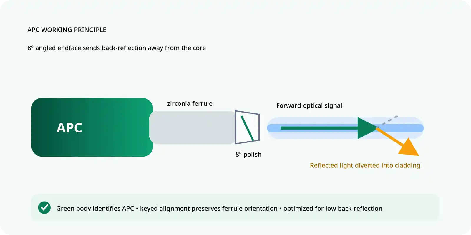
The apc connector (angled physical contact connector) is a specialized fiber optic termination. Engineers designed this apc fiber optic connector to reduce fiber optic back reflection by shaping the glass endface at a precise angle. Technicians can spot these parts right away because they use a bright Green color code on the body, the strain relief boot, and the mating adapter. This standard color prevents field workers from mixing mismatched connector types during quick installations or emergency repairs.
To work properly, two mating angled connectors must line up perfectly along their rotational axis. A strict key and keyway system makes this possible. The outer body of the plug has a raised physical key, and the mating adapter has a matching narrow slot. When you push the plug into the port, this guide forces both angled ferrules to meet in the exact same direction. Without this keyway, the sharp glass tips would smash into each other. That impact would create an air gap, and the spring inside the housing could easily shatter the delicate glass cores.
The angled shape is the secret behind the performance of this connector. Specifically, the 8° - APC connector endface polish angle redirects reflected light at a microscopic scale. During the early days of high-speed optical systems, engineers tested a wide 5° to 15° - APC connector endface polish angle range. They wanted the best balance between low insertion loss and high fiber connector return loss, which led to the modern standard angle.

| Metric / Standard | Value | Application Context / Impact |
|---|---|---|
| Industry Return Loss Minimum | -60 dB or greater | Standard minimum threshold to minimize backreflection toward the optical source |
| Field Mated Return Loss | -65 dB or greater | Expected performance value during active physical mating in field links |
| Unmated Port Return Loss | -65 dB or greater | Maintains reflection suppression on open distribution frame ports (vs. ~14 dB for UPC) |
| Typical Insertion Loss | 0.14 dB to 0.18 dB | Standard insertion loss range across modern single-mode manufacturing processes |
| Telcordia GR-326-CORE (Issue 3) | Standard Specification | Primary compliance guideline for single-mode optical connector performance |
| IEC 61755 Series | Geometry Standard | Defines technical dimensional parameters for endface curvature and apex offset |
| ITU-T G.671 | Component Standard | Governs transmission parameters and minimum standards for passive optical devices |
| IEC 61300 | Test Standard | Defines standardized attenuation and return loss optical test procedures |
| FiberExpress Fusion Splice-On | 0.3 dB max insertion loss | Exceeds standard loss requirements on OS2 single-mode termination assemblies |
| FiberExpress Brilliance Universal | 0.5 dB max insertion loss | Field-installable connector rated for minimum return loss threshold of -60 dB |
| Operating Wavelength Threshold | >1500 nm | Required threshold for RF video overlay and long-haul WDM transport systems |
| Mismatched Physical Mating | Core Misalignment | Mating directly to flat or UPC connectors causes physical damage and link failure |
When a laser pulse travels down the core and hits a connection point, a small portion of the light naturally bounces backward. This bounce is called Fresnel reflection, and it happens at the boundary where two glass surfaces touch. Because the angled physical contact connector has a slanted tip, this reflected light hits the outer core-cladding boundary at a steep angle. As a result, the light exceeds the critical angle needed for total internal reflection. Instead of traveling back down the core into the laser source, the reflected light leaks into the cladding and disappears safely as heat. This design stops reflected signals from causing interference, which stabilizes the transmitter and eliminates relative intensity noise.
APC vs UPC Fiber Connectors: Head-to-Head Comparison
Early networks used flat physical contact tips. Modern high-speed setups require a clear choice when comparing apc vs upc fiber connectors. You can quickly tell them apart in any patch panel by their color. A Blue color code marks the UPC type, while green marks the APC type.
Return loss is the main technical specification that separates these two designs. It measures the decibel ratio of light reflected back toward the transmitter. The -60 dB or greater - APC connector industry standard return loss creates an extremely stable environment for sensitive transceivers because only a tiny fraction of the light bounces back. In contrast, the -50 dB or greater - UPC connector industry standard return loss works well for normal digital data, but it struggles with analog RF signals or long-haul coherent optics.

When tested in the field using optical time-domain reflectometers, clean connections often beat these lab minimums. Technicians regularly measure a -65 dB or greater - APC connector field mated return loss. This high number shows just how well the angled polish clears away reflections when the tips are clean and seated tightly. Under the same clean conditions, flat-polished connections deliver a standard -55 dB - UPC connector field mated return loss.
Some sellers claim that APC insertion loss is higher than UPC insertion loss, but official standards do not treat this as a fixed rule. In early production runs, the angled cut made it harder to center the glass cores perfectly, which caused slight signal drops. Modern manufacturing and high-precision zirconia ceramic ferrules have resolved this issue. Today, both styles share the same 0.14 dB to 0.18 dB - APC and UPC connector typical insertion loss range when built by quality manufacturers.
| Feature | APC (Angled Physical Contact) | UPC (Ultra Physical Contact) |
|---|---|---|
| Endface Geometry | Angled polish | Flat spherical dome polish |
| Component Color | Green | Blue |
| Back Reflection Handling | Refracts light into cladding | Reflects light straight back down the core |
| Primary Use Case | Analog video, PON, long-haul | Digital Ethernet, enterprise LAN |
| Mating Compatibility | Strictly angled to angled | Strictly flat to flat |
When to Choose APC over UPC in Real-World Networks
Network designers choose connector types based on receiver sensitivity, physical network layout, and signal modulation.
FTTH/PON Networks
A pon apc connector setup uses singlemode fiber to send data from a central optical line terminal out to multiple customer homes through unpowered splitters. Because one laser feeds dozens of homes, any light bouncing off splitters or endpoints builds up quickly. This cumulative reflection degrades the main signal across the entire distribution tree. A ftth apc connector is required in these links to stop dangerous reflections and preserve the optical power budget over long spans.

RF/Video Systems
Radio frequency video networks, such as CATV overlays, rely on amplitude modulation. This analog transmission method is very sensitive to multipath interference. When light bounces back and forth between two flat connectors, it creates a delayed copy of the original signal. On an analog TV channel, this delay appears as ghosting or heavy picture distortion. The angled polish dumps unwanted reflections into the cladding, which stops multipath interference and delivers a crisp video stream.
Home Networks
When running a final drop into a home router or media converter, the performance gap between APC and UPC is hard to notice during everyday gigabit web browsing, and standard rules do not strictly require angled tips for basic internet. Even so, many DIY users install angled connectors inside their home wiring. This setup ensures full compatibility with next-generation bidirectional transceivers and multi-gigabit PON upgrades. Using angled terminations for all in-wall singlemode fiber is a great way to future-proof a home network.
Fiber Sensing
Advanced systems like distributed acoustic sensing and structural health monitoring read tiny changes in Rayleigh backscatter along the glass to detect movement or temperature shifts. These instruments are extremely sensitive. Even the tiny reflection from an angled connector can blind their avalanche photodiodes. Because of this risk, engineers avoid mechanical connectors entirely on the sensing lines and use fusion splices instead. They reserve mechanical plugs strictly for the final equipment ports.
Can You Mix APC and UPC Connectors?
Do not mix these two connector types under any circumstances. If you try to mate an angled ferrule with a flat UPC ferrule, you will destroy the glass surfaces and break the optical link.
When you push a green connector into an adapter containing a blue connector, the mismatched tips cannot touch evenly. The 8-degree slope on the green ferrule hits the curved dome of the blue ferrule at an awkward angle. This mismatch leaves a permanent, uneven wedge of air between the two fiber cores.

Mismatched Mating Failure:
Green (APC) 8° Angle   |   Blue (UPC) Flat Dome
\                  |          )
\                 |         )   <-- Crushes at single contact point
\   [Air Gap]    |        )
\               |       )
- The mechanical adapter forces the green APC ferrule and blue UPC ferrule together inside the alignment sleeve.
- The 8-degree angled surface collides with the flat, dome-shaped UPC surface at a single microscopic point.
- The mismatched tips cannot sit flush, leaving an asymmetric air gap across the central optical path.
- Laser light leaves the transmitting core, hits the open air gap, and scatters away instead of entering the receiving fiber.
- The spring inside the adapter concentrates all its clamping force onto the tiny contact point, permanently scratching, chipping, and crushing the glass cores.
Optically, this large air gap causes extreme signal attenuation. Light simply scatters into the open space instead of entering the receiving fiber, causing immediate packet loss and dropped connections.
Mechanically, the damage is permanent. The spring inside the adapter pushes the ferrules together with continuous force. Because the two surfaces do not match, that spring force concentrates on one tiny contact point. This intense pressure cracks, scratches, and crushes the glass cores and ceramic tips. If you plug the wrong cable into an expensive optical transceiver, you will ruin the transceiver port permanently.
If your patch panel port and your equipment port do not match, use a hybrid patch cord. A hybrid patch cord has a green connector on one end and a blue connector on the other. It converts the connection safely along the fiber without forcing mismatched tips together inside an adapter.
Return Loss Decibel Ranges and Industry Standards
To evaluate return loss properly, you must look at both mated and unmated states. Mated numbers matter when active links carry traffic, but unmated numbers determine how safe open distribution panels are.
In a fiber distribution hub, many ports sit open and disconnected until a customer buys service. When an open port carries live laser light, the signal hits the bare glass-to-air boundary and reflects backward. An unmated apc fiber optic connector delivers a -65 dB or greater return loss, which keeps dangerous reflections from reaching and destabilizing the upstream optical line terminal. In contrast, an unmated UPC port provides only about ~14 dB of return loss. It acts like a mirror and shoots a strong blast of optical power straight back toward the laser. For this reason, telecom operators require angled connectors on all active distribution frames and optical splitters.
International standards organizations publish clear mechanical and optical specifications to guarantee that parts from different vendors work together seamlessly.
The GR-326-CORE issue 3 document from Telcordia sets the main baseline for singlemode connector reliability. It tests how well connectors survive severe temperature swings, high humidity, and mechanical pulling without losing signal quality.
The IEC 61755 series controls ferrule dimensions. It sets strict tolerances for endface curvature, apex offset, and fiber undercut or protrusion. Thanks to this standard, a cable built in one factory will mate reliably with an adapter built by a different company.
Finally, ITU-T G.671 defines optical performance requirements for passive components across broader telecom networks, ensuring consistent signal quality from end to end.

APC vs UPC Fiber Connector Cleaning Procedures
Most field issues are caused by dirty endfaces rather than broken hardware. Because angled connectors have a slanted tip, you must clean them carefully so you do not drag debris into the light path.
A simple push-button pen cleaner is often not enough for heavy grime like finger oils, dried buffer gel, or job-site dust. A better method combines a digital inspection scope with a reel-style cassette cleaner. The scope lets you identify the exact contamination, while the cassette provides a fresh, lint-free microfiber wipe for every swipe. For tough grime, add a drop of fast-evaporating optical solvent to the cleaning ribbon before wiping the ferrule across it.
Some technicians in specialized sensing labs apply index matching gel to suppress reflections during quick bench tests on flat connectors. Never use index matching gel in telecommunications or FTTH networks. The gel leaves behind an oily film that attracts airborne dirt over time. That dirt turns into a dark sludge that blocks the optical signal, forcing you to throw the patch cable away.
Always check your cleaned ends against the IEC 61300 testing standard. This standard sets clear visual pass/fail rules for scratches, pits, and contamination across the core, cladding, adhesive layer, and outer contact zones.

| Step | Action | Rationale |
|---|---|---|
| 1 | Inspect the endface with a digital probe | Identifies the type of contamination (dust vs oil) and prevents grinding hard particles into the glass core during the wiping phase. |
| 2 | Advance the cleaning cassette ribbon | Ensures a pristine, unused section of microfiber is available. Reusing a section causes cross-contamination. |
| 3 | Apply optical solvent (if wet cleaning) | Breaks down stubborn oils and static bonds holding dust to the ceramic. Standard isopropyl alcohol leaves a film and should be avoided. |
| 4 | Drag the ferrule across the ribbon | Apply light pressure and drag in one continuous motion. For angled connectors, ensure the 8-degree slope sits flat against the ribbon. |
| 5 | Re-inspect the endface | Confirms the contamination is completely removed before mating. Mating a dirty connector embeds the dirt permanently into the glass. |
Common Form Factors: SC, LC, and FC Variants
The internal polish type works independently from the outer plastic or metal shell. You choose the outer housing style based on your panel space and the physical demands of the job site.

SC/APC
The sc/apc connector uses the subscriber connector form factor. It features a square plastic body that locks into place with a smooth push-pull motion. This push-pull design lets technicians plug and unplug lines quickly without twisting the cable, which protects the inner glass from harmful torsional stress. It uses a strong 2.5 mm ceramic ferrule that handles frequent plugging very well. It is the primary connector used on residential optical network terminals and wall-mounted fiber boxes.
LC/APC
The lc/apc connector uses the lucent connector form factor. Engineers created it to save space in busy data centers and central offices. It uses a compact 1.25 mm ferrule and a flexible latching clip just like an RJ-45 Ethernet plug. Its small size lets equipment makers double or triple the port count on switches, line cards, and high-density patch panels. Consider this compact style for dense wavelength division multiplexing gear and large distribution frames where rack space is limited.
FC/APC
The ferrule connector uses a durable metal body with a threaded screw-on nut. Instead of relying on a plastic latch that might snap under tension, this metal nut screws tightly onto the mating barrel. We install this rugged variant in high-vibration locations like factory floors, cellular towers, and moving trains. In these rough settings, plastic latches can shake loose over time, but a threaded metal ferrule connector stays locked in place to maintain a steady physical connection.