The fiber MPO connector stands as a linchpin in modern telecommunications infrastructure, engineered to consolidate multiple optical channels into a singular, mechanically transferable (MT) ferrule interface. Operating across 8, 12, 16, or 24 fiber configurations-with specialty variants extending to 72 fibers for large-scale optical switching matrices-this multi-fiber push-on architecture has fundamentally altered the economics and physics of high-density interconnection. The answer to whether these connectors handle high bandwidth isn't merely affirmative; it's the reason data center engineers sleep at night.

Parallel Optics Changed Everything
Back when 10 Gigabit Ethernet felt like overkill, nobody anticipated the bandwidth explosion that cloud computing and AI model training would demand. The industry responded with parallel optics-a transmission paradigm where multiple fiber lanes operate simultaneously rather than shoving more bits down a single strand. This is where MPO multi-fiber connectors became indispensable.
Take 40GBASE-SR4 as an example. Four transmit fibers push 10 Gbps each while four receive fibers mirror that throughput. An 8-fiber MPO handles it cleanly. Move up to 100GBASE-SR4, and the same physical interface accommodates 25 Gbps per lane across those eight fibers. The connector didn't change. The encoding and transceiver technology did.
400G parallel applications? Still MPO territory. QSFP-DD and OSFP transceivers leverage either 8-fiber configurations with 100 Gbps per lane (thanks to PAM4 modulation advances) or 16-fiber arrangements for 400G-SR8 deployments. The 800G generation arriving in hyperscale facilities uses those 16-fiber MPO interfaces with 8 transmit and 8 receive channels operating at 100 Gbps apiece.
Nobody in 1996 designing the original MTP connector with US Conec and Corning foresaw 1.6 Terabit applications. Yet the form factor persists. That's remarkable staying power for what amounts to a precision-ground plastic ferrule.

Loss Budgets Get Brutal at Speed
Here's something that doesn't appear in marketing collateral often enough: faster doesn't mean more forgiving. The 40G multimode SR4 standard allowed 1.5 dB insertion loss from transceiver to transceiver. Compare that with the typical 2.2 dB sensitivity headroom in the transceivers themselves, and you've got a 0.7 dB "guard band" for real-world messiness-contamination, manufacturing tolerances, test equipment accuracy.
That guard band shrinks as speeds increase.
Fiber MPO connector performance hinges on end-face geometry parameters codified in IEC PAS 61755-3-31. Polish angle, fiber protrusion height, height differential across the array. When twelve or sixteen fiber tips must achieve physical contact simultaneously within a ferrule footprint smaller than your thumbnail, the mechanical precision requirements become genuinely impressive. A height variance exceeding specification means some fibers mate properly while others exhibit elevated insertion loss or degraded return loss.
The contamination sensitivity compounds everything. Industry estimates suggest 80% of fiber network failures trace back to connector contamination. One particle on one fiber end-face within an MPO-24 can cascade through the entire link. Field technicians who've spent forty-five minutes chasing intermittent loss issues only to discover microscopic debris tend to develop religious devotion to inspect-before-mate protocols.
Why 16-Fiber Variants Matter Now
The 12-fiber MPO dominated for years. Applications needing only 8 active fibers (like 40G and 100G SR4) simply left the middle four positions unused-wasteful, but functional. Then 400G-SR8 and 800G-SR8 entered the picture.
Eight transmit plus eight receive equals sixteen fibers. The 16-fiber MPO connector addresses this directly, packing fibers into a single row with a shifted key design preventing accidental mating with 12 or 24-fiber variants. Physical damage prevention through incompatibility.
US Conec's MTP-16 and Senko's SN-MT represent next-generation very small form factor (VSFF) implementations of this concept. The density improvements are staggering: 216 SN-MT connectors fit where 80 traditional 16-fiber MPOs would occupy. For hyperscale operators where rack space directly correlates to operational expenditure, that ratio justifies immediate adoption.
Single-mode versions with angled physical contact (APC) polish are pushing into 800G-DR8 and LR8 applications over longer reaches. The back-reflection suppression that APC provides becomes non-negotiable when PAM4 modulation's reduced signal-to-noise ratio leaves no margin for reflected energy interference.

The Polarity Problem Persists
Anyone who's spent real time in data center structured cabling knows polarity management remains the most frustrating aspect of multi-fiber connectivity. Three standardized methods (Type A, B, and C) attempt to ensure transmitters connect to receivers through various cassette and trunk cable combinations. TIA-568.3-E recently introduced universal polarity methods U1 and U2 to simplify deployments, but legacy installations remain a patchwork.
Wrong polarity type selection doesn't cause immediate catastrophic failure. It causes the maddening symptom of "some ports work, some don't" that consumes troubleshooting hours. Technicians swap patch cords unnecessarily. Equipment gets RMA'd without actual defect. The operational cost of polarity confusion across a 5,000-port deployment adds up faster than procurement teams realize.
Visual fault locators help. Dedicated polarity verification instruments help more. But nothing replaces documentation discipline during initial installation-discipline that time pressure and budget constraints routinely compromise.
Testing MPO Interfaces: Tier 1 vs. Tier 2
Certification testing for MPO-terminated links follows the same tier structure as single-fiber certification. Tier 1 (basic) captures loss, length, and polarity per channel. Tier 2 (extended) adds OTDR characterization showing attenuation, splice quality, and connector reflectance along the link's entire length.
The math on test confidence gets uncomfortable with multi-fiber connectors. Consider: at 95% confidence (2-sigma), roughly 5% of individual fiber test results may fall outside expected accuracy. For a duplex LC link, that's manageable. For a 12-fiber MPO, twelve independent 5% probabilities compound to roughly 60% chance that at least one fiber measurement falls outside expected accuracy per connector.
This isn't a flaw in MPO technology. It's statistical reality that test methodologies must accommodate. Hyperscale operators typically establish custom acceptance criteria rather than relying on generic standards, precisely because their deployment scale makes false rejects operationally expensive while false accepts create downstream troubleshooting burden.
Modern test equipment like Fluke's MultiFiber Pro or VIAVI's solutions streamlined what used to require fan-out cables and channel-by-channel verification using duplex OLTS equipment. Testing MPO cables with single-fiber instruments still works but consumes disproportionate technician time and increases contamination risk through repeated mating cycles.

400G and 800G: MPO Remains Central
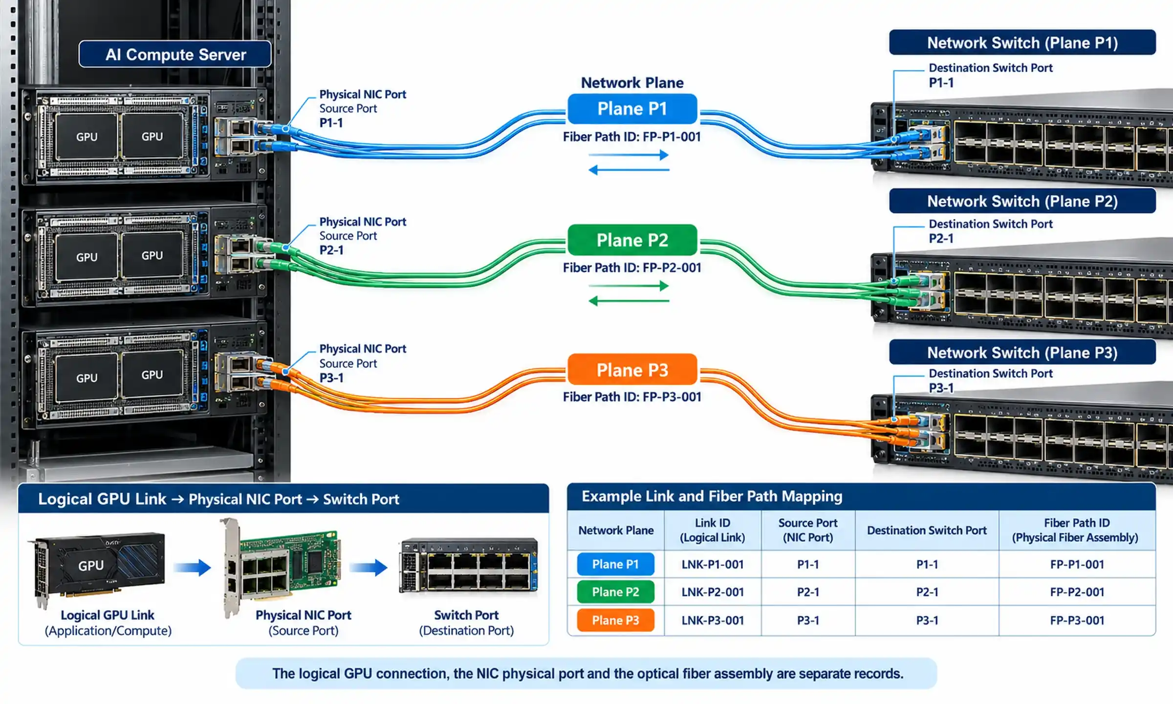
AI training clusters in Northern Virginia, Singapore, and Dublin are pushing traffic densities that would have seemed absurd five years ago. GPU-to-GPU interconnects within compute pods demand 400G and 800G bandwidth with latency sensitivity measured in microseconds. The fiber MPO connector infrastructure enabling these workloads looks unremarkable-pre-terminated trunk cables, cassettes, patch panels-but represents decades of mechanical refinement.
The QSFP-DD and OSFP transceiver form factors that drive these speeds assume MPO interfaces. Breakout cables convert MPO-12 or MPO-16 terminations to LC duplex for compatibility with legacy equipment or lower-speed server NICs, maximizing port utilization and preserving investment across technology generations.
What about alternatives? LC duplex remains dominant for single-channel applications and long-haul WDM deployments. SN and CS connectors address VSFF requirements where even MPO density proves insufficient. But for parallel short-reach optics in the 100G through 800G range, multi-fiber MPO connectors remain the default interface. Ecosystem support-transceivers, cables, cassettes, test equipment-creates momentum that alternative connector types struggle to overcome.
Installation Realities Field Engineers Know
Theoretical bandwidth capacity means nothing if field installation compromises connector integrity. MPO ferrule end-faces demand inspection and cleaning protocols that LC and SC connectors can sometimes tolerate skipping. The larger mating surface area allows contamination migration during cleaning attempts-dirt from position one moving to position two as the cleaning cloth traverses.
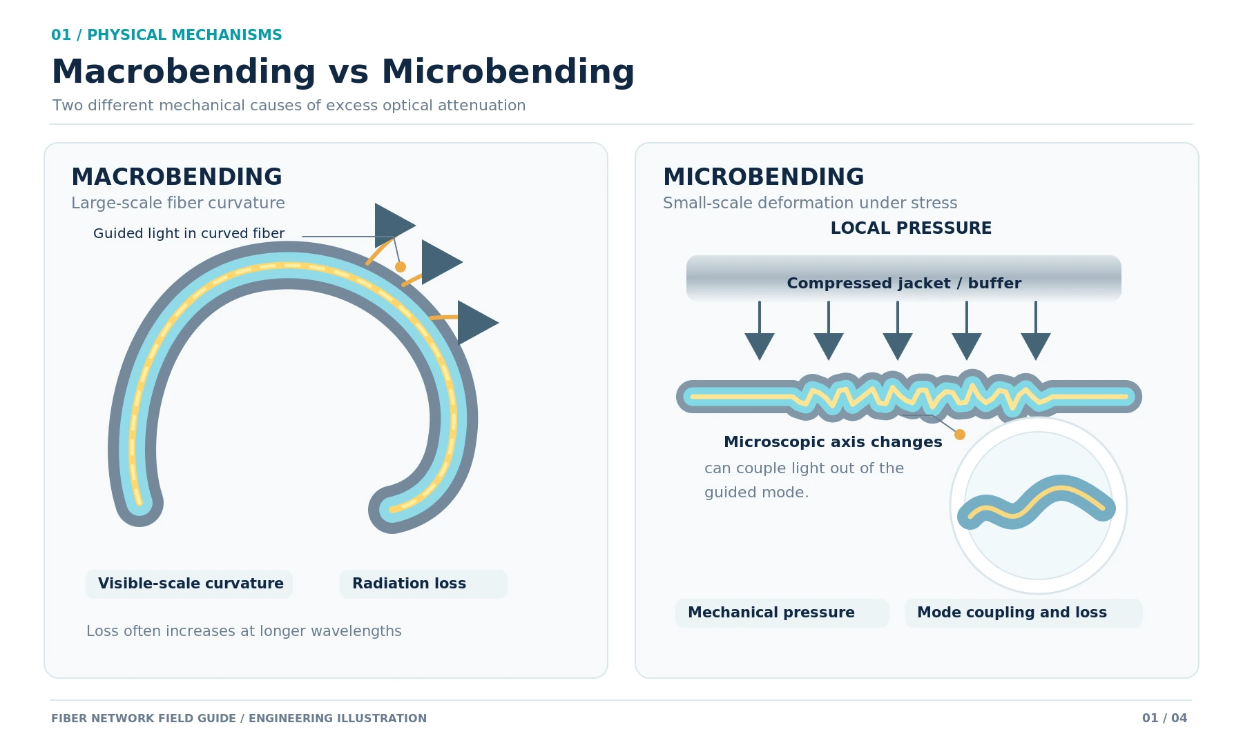
Experienced installers inspect before cleaning to avoid making pristine connectors dirty. They reinspect after cleaning to verify results. They understand that bend radius violations in trunk cable routing create macrobend losses invisible during installation but devastating to link budgets. They recognize that fiber count mismatches between components cause alignment failures that no amount of cleaning resolves.
The gap between textbook installation practice and deadline-pressured reality determines real-world MPO performance. Contractors bidding competitively don't always allocate adequate labor hours for proper certification. Network owners who skip acceptance testing discover problems months later when application traffic exposes marginal links.
What 1.6 Terabit Means for Connector Evolution
If 800G represents today's leading edge, 1.6 Terabit per lane looms on roadmaps. The 16-fiber MPO architecture supporting 800G extends naturally: 8 transmit fibers at 200 Gbps per lane plus 8 receive fibers equals 1.6 Tbps aggregate. The connector mechanical interface doesn't fundamentally change. Transceiver optoelectronics and modulation formats carry the engineering burden.
Co-packaged optics and on-board optics approaches aim to move photonics closer to switch ASICs, potentially reducing inter-rack cabling distances. Whether these architectures diminish MPO relevance remains speculative. The multi-fiber connector format may simply shift from rack-to-rack interconnection to internal chassis boundaries. The precision alignment requirements and contamination sensitivity won't disappear regardless of where connectors terminate.
The Bandwidth Question, Answered Directly
Can fiber MPO connectors handle high bandwidth? They're currently supporting 800 Gbps in production environments and scale to 1.6 Tbps under existing interface specifications. The connector format that seemed purpose-built for 40G applications in the mid-2010s extends gracefully through multiple technology generations by accommodating denser fiber counts, tighter manufacturing tolerances, and improved transceiver lane rates.
The limiting factors aren't MPO mechanical limitations. They're loss budgets, contamination control, polarity management, and installation quality. Organizations deploying high-bandwidth infrastructure with multi-fiber MPO cabling achieve success through inspection discipline, proper test methodology selection, and documentation practices that enable future troubleshooting.
For data center architects evaluating structured cabling investments, MPO-based trunk infrastructure provides migration pathways from 100G through 400G to 800G without wholesale replacement. The 8-fiber and 16-fiber variants address current parallel optics requirements while 24-fiber configurations offer expansion headroom. Pre-terminated assemblies reduce deployment timelines compared to field termination, and cassette-based architectures simplify moves-adds-changes throughout facility lifecycles.
The multi-fiber MPO connector doesn't merely handle high bandwidth. In parallel optics deployments that dominate hyperscale and enterprise data centers, it remains the only practical interface choice. That market position wasn't accidental. Three decades of mechanical refinement, standards development, and ecosystem buildout created infrastructure that bandwidth growth has validated rather than obsoleted.