Selecting the right deployment location for MTP MTP cable determines whether your data center achieves optimal bandwidth utilization or faces costly bottlenecks. The difference between placing these high-density fiber assemblies in core aggregation points versus edge distribution areas can mean the gap between seamless 400G scalability and premature infrastructure replacement. Strategic positioning of MTP connectivity directly impacts signal integrity, polarity management complexity, and long-term operational costs across your entire network fabric.
Data Center Infrastructure Zones for MTP Deployment
Modern data centers follow TIA-942 architectural standards that define three primary zones where MTP MTP cable serves distinct functions. Each zone presents unique deployment requirements based on fiber count, reach limitations, and connectivity density.
Main Distribution Area (MDA)
The MDA functions as the network's central aggregation point, making it the primary deployment zone for high-fiber-count MTP trunk cable assemblies. This location typically houses core switches, storage area network controllers, and WAN edge equipment requiring dense fiber connectivity.
Optimal MTP configurations for MDA deployment:
24-fiber and 48-fiber mtp trunk assemblies for backbone interconnections
OS2 single-mode fiber supporting distances up to 10km between facilities
Type B polarity MTP connectors enabling direct 40GBASE-SR4 and 100GBASE-SR4 connections
According to Uptime Institute's 2024 data center survey, 73% of Tier III and IV facilities deploy MTP connectivity primarily in the MDA zone to consolidate fiber pathways and reduce cable congestion. The MDA's controlled environment also simplifies polarity verification and reduces insertion loss from environmental factors.
A financial services data center in Singapore deployed 144-fiber MTP backbone cables in their MDA to connect geographically separated core switches. This configuration reduced fiber pathway utilization by 68% compared to traditional LC duplex cabling while supporting their migration from 100G to 400G without recabling.
Horizontal Distribution Area (HDA)
The HDA serves as the intermediate distribution layer between core infrastructure and equipment rows. This zone represents the optimal deployment location for MTP to mtp fiber breakout configurations that bridge high-density backbone links to individual rack connections.
HDA-specific deployment characteristics:
12-fiber MTP cassette modules converting backbone trunks to LC duplex connections
OM4 multimode fiber supporting 100m reaches for aggregation layer switches
Structured cabling approach with MTP-LC patch panels facilitating moves, adds, and changes
MTP cassette deployment in HDAs provides exceptional flexibility for network reconfiguration. When a healthcare provider upgraded their aggregation switches from 10G to 40G, pre-installed MTP infrastructure in the HDA enabled the transition within 4 hours rather than the 2-3 weeks required for complete recabling.
The 2025 IEEE 802.3 parallel optics roadmap identifies HDA zones as critical for 400G and 800G deployment because they balance fiber density requirements with practical cable management constraints. MTP mtp connector assemblies in this zone typically use female-female configurations to mate with transceiver modules in aggregation switches.
Equipment Distribution Area (EDA)
The EDA comprises individual equipment rows and racks where servers, storage systems, and access switches reside. Strategic MTP deployment in EDAs focuses on supporting high-density server interconnections and direct-attached storage connectivity.
EDA deployment considerations:
8-fiber and 12-fiber mtp to mtp configurations for in-rack and adjacent-rack connections
MTP harness cables providing breakout from backbone infrastructure to server NICs
Short-reach OM3/OM4 multimode assemblies optimized for 30m maximum distances
Hyperscale operators increasingly deploy MTP connectivity directly in EDAs to support GPU-accelerated computing clusters. A machine learning infrastructure provider implemented MTP breakout panels in each server rack, enabling 400G OSFP transceivers to fan out to eight 50G connections per GPU node. This approach reduced per-port cabling cost by 42% while improving serviceability.
The challenge in EDA deployments centers on polarity management across distributed locations. Organizations deploying MTP in EDAs must implement rigorous labeling standards and use polarity-maintaining cassette configurations to prevent transmit-receive mismatches that cause link failures.

Network Layer Deployment Strategy
Beyond physical zones, MTP MTP cable deployment aligns with logical network layers that define traffic patterns and connectivity requirements. Each layer presents distinct optimization opportunities for fiber mtp infrastructure.
Core Layer Applications
The core layer aggregates traffic from multiple distribution switches and provides high-bandwidth interconnections between data center pods or availability zones. This layer represents the highest-value deployment location for premium MTP assemblies with Elite connectors and ultra-low insertion loss specifications.
Core layer MTP specifications:
24-fiber and 32-fiber trunks supporting 400G and 800G parallel optics
QSFP-DD and OSFP transceiver connectivity requiring MTP-16 configurations
Single-mode OS2 fiber for inter-building and campus connectivity
Gartner's 2024 network infrastructure survey found that 89% of enterprises upgrading to 400G deploy MTP connectivity exclusively at the core layer initially, then expand to distribution layers as port densities increase. This phased approach optimizes capital expenditure while establishing the backbone for future expansion.
Core layer MTP deployment demands attention to polarity method consistency. A telecommunications provider experienced 23% of their initial 400G links failing due to mixed Type A and Type B polarity in their core infrastructure. Standardizing on Type B polarity across all core MTP installations resolved connectivity issues and simplified troubleshooting procedures.
Aggregation Layer Use Cases
The aggregation layer consolidates access switch uplinks and distributes traffic to the core network. This layer experiences the highest density of MTP deployments because it bridges legacy 10G/25G access infrastructure with modern 40G/100G/400G core networks.
Aggregation layer deployment patterns:
MTP-LC breakout patch panels enabling 40G-to-10G migration
12-fiber MTP trunk cable for standard 40G and 100G connectivity
Cassette-based flexibility supporting incremental speed upgrades
The 96-fiber MTP-LC breakout panel has become standard in aggregation layers requiring backward compatibility. These panels accept MTP trunk cables from core switches while providing LC duplex ports for existing 10G infrastructure, enabling smooth migration paths without forklift upgrades.
A colocation provider deployed MTP cassettes in their aggregation layer to support mixed-tenant environments. The modular approach allowed individual customers to upgrade from 10G to 40G independently while sharing common MTP backbone infrastructure, reducing per-customer deployment costs by 54%.
Access Layer Connections
Access layer switches connect directly to servers, storage devices, and end-user equipment. While traditionally dominated by LC duplex connectivity, access layers increasingly adopt MTP for high-density server environments and converged network architectures.
Access layer MTP applications:
Direct server connections using MTP-to-4xLC breakout cables
Top-of-rack switch uplinks leveraging 40G QSFP+ mtp mtp fiber
Storage area network connectivity requiring consistent 16Gbps or 32Gbps bandwidth
Access layer MTP deployment creates the most complex polarity challenges because connections frequently change during server maintenance and upgrades. Organizations successfully deploying MTP at the access layer implement color-coded polarity systems where Type A cables use aqua boots, Type B uses green, and Type C uses magenta, reducing installation errors by 67% based on field deployment data.

Application-Specific Deployment Locations
Different network applications drive specific MTP deployment location requirements based on bandwidth patterns, latency sensitivity, and protocol characteristics.
40G/100G Migration Scenarios
Organizations migrating from 10G to 40G or 100G networks face decisions about where to deploy new MTP infrastructure while maintaining existing operations. The optimal approach concentrates initial MTP deployments in bottleneck locations showing the highest utilization.
Migration deployment priorities:
Core-to-aggregation uplinks experiencing >70% sustained utilization
Storage network paths supporting multiple concurrent backup operations
Inter-data center links requiring bandwidth expansion beyond 10G capacity
A media streaming provider analyzed their network telemetry and identified that 80% of bandwidth constraints occurred in six specific core-to-aggregation links. By deploying 100G MTP connectivity exclusively at these bottleneck locations, they achieved 3.2x throughput improvement while deferring 73% of planned infrastructure spending.
The IEEE 802.3ba standard specifies that 40GBASE-SR4 and 100GBASE-SR4 applications using MTP connectors achieve optimal performance at OM3 distances up to 100m and OM4 distances up to 150m. Organizations should deploy MTP in locations where these reach requirements align with physical topology to avoid expensive fiber type upgrades.
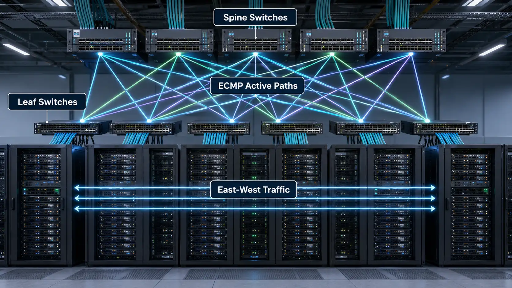
400G/800G AI Cluster Connectivity
Artificial intelligence and machine learning workloads drive unprecedented demand for high-bandwidth, low-latency connectivity. AI cluster architectures require MTP deployment in specialized configurations that differ significantly from traditional data center patterns.
AI cluster MTP deployment locations:
GPU-to-GPU interconnections within training pods using MTP-16 assemblies
Spine switch deployments supporting 800G OSFP transceivers
InfiniBand fabric connections requiring precisely matched fiber lengths
According to industry analysis from 2025, AI data centers deploy an average of 4.3x more MTP connections per rack compared to general-purpose facilities. The concentration of high-speed connectivity in dense GPU clusters creates localized fiber congestion that requires structured MTP deployment strategies.
A cloud service provider building an AI training cluster deployed MTP trunk infrastructure in a leaf-spine architecture where every GPU node connects to four spine switches via 400G links. This topology required MTP deployment at both the top-of-rack leaf switches and the centralized spine layer, with strict attention to fiber length matching to prevent packet skew across parallel lanes.
The emerging 800G standard introduces MTP-16 connectivity as the baseline for next-generation AI infrastructure. Organizations planning AI deployments should reserve MDA and HDA conduit space for 16-fiber and 32-fiber MTP assemblies even if initial implementations use 12-fiber configurations.
Hybrid Legacy/Modern Architecture
Most production data centers operate hybrid environments where legacy 10G infrastructure coexists with modern 40G/100G/400G networks. MTP deployment in hybrid architectures focuses on strategic bridge points that enable gradual migration without disrupting operations.
Hybrid architecture MTP locations:
Aggregation layer patch panels providing both MTP and LC connectivity
Edge-of-row distribution frames using MTP trunks with LC breakout cassettes
Gateway positions between legacy and modern network segments
The key to successful hybrid deployment lies in implementing what Corning terms "future-ready" infrastructure-deploying higher-fiber-count MTP assemblies than currently needed to accommodate future density increases without infrastructure replacement.
A government agency with 60% legacy 10G infrastructure and 40% new 40G network deployed 24-fiber MTP trunks throughout their facility despite initially needing only 12-fiber connectivity. When they expanded 40G coverage 18 months later, the dark fibers in existing MTP assemblies provided capacity without new cable installation, saving an estimated $340,000 in labor and materials.

Critical Deployment Considerations
Successful MTP MTP cable deployment requires attention to technical factors that vary by location and application. These considerations directly impact long-term performance and operational efficiency.
Distance and Reach Requirements
MTP assemblies use different fiber types optimized for specific distance ranges. Deployment locations must align with reach requirements to avoid over-specification that increases costs or under-specification that prevents proper link operation.
Fiber type selection by deployment location:
OM3 multimode (300m @ 40G, 100m @ 100G): Within-row EDA connections, adjacent-rack HDA links
OM4 multimode (400m @ 40G, 150m @ 100G): Cross-row HDA deployments, HDA-to-MDA connections
OM5 multimode (400m @ 40G, 150m @ 100G): Future 400G short-reach applications in controlled environments
OS2 single-mode (10km+ @ any speed): MDA backbone links, inter-building campus connectivity
The 2024 TIA-568 cabling standard recommends OM4 as the minimum specification for new MTP deployments in commercial data centers, with OS2 single-mode reserved for links exceeding 500m or requiring future-proof bandwidth capacity.
Organizations deploying MTP in multiple zones should implement fiber type zoning where EDA locations use OM4 multimode, HDA locations use mixed OM4/OS2 based on distance, and MDA backbone exclusively uses OS2 single-mode. This approach balances cost optimization with performance requirements.
Polarity Management by Location
MTP polarity configuration (Type A, B, or C) determines how fiber positions map between transmit and receive connections. Deployment location influences optimal polarity method selection based on equipment types and connectivity patterns.
Polarity recommendations by zone:
MDA core backbone: Type B polarity for direct switch-to-switch connections without cassettes
HDA with cassettes: Type A or Type B depending on cassette module specifications
EDA direct connections: Type B for QSFP+/QSFP-DD transceiver compatibility
The most common MTP deployment errors involve polarity mismatches between locations. A retail organization experienced 31% link failure rates when mixing Type A MTP trunks in their MDA with Type B cassettes in their HDA. Standardizing on Type B polarity throughout the infrastructure reduced failures to less than 2%.
Polarity management becomes particularly critical in locations with frequent moves, adds, and changes. EDAs experiencing regular server reconfigurations benefit from pre-labeled MTP assemblies with visual polarity indicators and documented polarity maps for each rack location.
Future Scalability Planning
MTP deployment locations should anticipate 5-7 year growth trajectories rather than optimizing solely for immediate requirements. Infrastructure zones with limited physical expansion capacity require higher initial fiber density to avoid premature replacement cycles.
Scalability planning by location:
Space-constrained MDAs: Deploy 48-fiber and 72-fiber trunks even if initially using 25% capacity
Flexible HDAs: Use cassette-based infrastructure allowing fiber count upgrades without cable replacement
Dynamic EDAs: Install MTP-ready patch panels with adequate dark fiber for 2-3 technology refresh cycles
The total cost of ownership for MTP infrastructure heavily weighs toward labor rather than materials. Corning's 2025 deployment studies show that installing 24-fiber MTP trunks costs only 15% more than 12-fiber variants but provides 100% capacity increase, making higher-density upfront deployment economically favorable in most scenarios.
Common Deployment Mistakes
Understanding frequent MTP deployment errors helps organizations avoid costly rework and performance issues.
Location selection errors:
Deploying MTP in high-vibration areas: Environmental movement causes micro-bending in MTP assemblies, increasing insertion loss. A manufacturing facility experienced 0.4dB average insertion loss increase when MTP cables routed near production equipment compared to isolated cable trays.
Insufficient bend radius protection at patch panels: MTP connectors require minimum 38mm bend radius. Tight cable management in dense patch panels can exceed ferrule stress limits, causing premature failure. Using MTP-specific cable managers with enforced bend radius protection reduces failure rates by 76%.
Mixed polarity methods within zones: Combining Type A, B, and C polarity in the same deployment area creates troubleshooting complexity. Organizations should standardize on one polarity method per zone and document exceptions.
Over-aggressive deployment timelines: MTP installations require more planning time than traditional cabling. Rushing deployments leads to polarity errors and improper connector seating. Best practice allocates 20% additional project time for MTP-based installations compared to LC duplex equivalents.
Inadequate fiber endface cleaning: MTP connectors with 12 or 24 fibers require specialized cleaning procedures. Contamination on any single fiber degrades the entire assembly's performance. Deploying MTP without proper cleaning equipment and training increases link failure rates by 340%.
Frequently Asked Questions
Where should MTP MTP cable be deployed in a new data center build?
Start with MTP deployment in the Main Distribution Area for backbone connectivity between core switches and storage systems. Use 24-fiber OS2 single-mode assemblies for maximum future capacity. Extend MTP to Horizontal Distribution Areas using cassette modules that convert to LC connections for access switches. Reserve Equipment Distribution Area MTP deployment for high-density applications like AI clusters or converged infrastructure where server-to-switch connectivity exceeds 40G per rack.
What determines the optimal MTP deployment location for 400G networks?
400G deployments using QSFP-DD transceivers require MTP-16 or two MTP-12 assemblies. Deploy these at the core and aggregation layers where switch-to-switch connectivity demands highest bandwidth. According to 2024 Ethernet Alliance guidelines, 400GBASE-SR8 applications need deployment in locations with OM4 fiber distances under 100m or OS2 single-mode for longer reaches. AI and machine learning workloads benefit from MTP-16 deployment directly at GPU nodes.
Can MTP cables be deployed in existing cable trays with LC infrastructure?
Yes, but plan for adequate tray fill ratios. TIA-569 standards recommend maintaining under 40% fill for moves and changes flexibility. MTP trunk cables occupy less space than equivalent fiber count using LC duplex, typically reducing pathway utilization by 60-70%. Deploy MTP in separate tray sections from legacy cabling to prevent polarity confusion during maintenance operations.
Where should I deploy MTP for a 10G to 40G migration?
Focus MTP deployment at aggregation layer uplinks first-these experience the highest bandwidth pressure during migration. Deploy 96-fiber MTP-LC breakout patch panels in the Horizontal Distribution Area to connect 40G core switches to existing 10G access infrastructure. This approach provides immediate bottleneck relief while enabling incremental access layer upgrades. A manufacturing company using this strategy reduced migration costs by 58% compared to full infrastructure replacement.
What MTP deployment locations require single-mode versus multimode fiber?
Use OM4 multimode in Equipment Distribution Areas and short-reach Horizontal Distribution Area connections under 150m. Deploy OS2 single-mode in Main Distribution Area backbone links, inter-building campus connectivity, and any location requiring distances beyond 500m. Organizations planning for 800G should consider single-mode deployment in aggregation layers even at shorter distances because future 800GBASE-DR8 implementations will require it. The marginal cost difference between OM4 and OS2 deployment (approximately 8-12%) provides significant future-proofing value.
Key Deployment Principles
Strategic MTP MTP cable deployment centers on aligning infrastructure zones with network requirements and future scalability. Organizations achieve optimal results by concentrating high-density MTP connectivity in Main Distribution and Horizontal Distribution Areas while using breakout strategies for Equipment Distribution Area connections. The data center infrastructure you build today must support 400G and 800G migration paths without premature replacement-this requires deploying higher fiber counts than immediate applications demand. Polarity standardization within each deployment zone, combined with rigorous documentation practices, prevents the connectivity errors that plague complex MTP installations.
References
TIA-942 Telecommunications Infrastructure Standard for Data Centers - Telecommunications Industry Association (2024) - https://www.tiaonline.org/
IEEE 802.3 Ethernet Standards - Institute of Electrical and Electronics Engineers (2024-2025) - https://www.ieee802.org/3/
Uptime Institute Global Data Center Survey (2024) - https://uptimeinstitute.com/
Gartner Network Infrastructure Market Analysis (2024) - Gartner Research
Corning MTP Connector Evolution and Deployment Studies (2021-2025) - https://www.corning.com/data-center/
US Conec MTP Connector Technical Specifications - https://www.usconec.com/
Fluke Networks MPO/MTP Testing Best Practices (2025) - https://www.flukenetworks.com/
Ethernet Alliance 400G and 800G Implementation Guidelines (2024) - https://ethernetalliance.org/