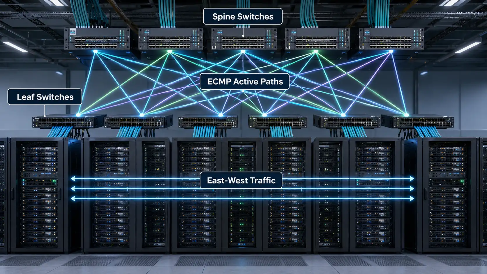

Spine-leaf architecture is a two-tier data center network design in which every leaf switch connects to every spine switch, creating a fabric where traffic crosses a predictable number of hops and can use many active paths at once. Instead of the older access, aggregation and core hierarchy, a spine-leaf network gives server-to-server traffic a consistent path length, steadier latency and bandwidth that scales by adding switches rather than replacing them.
The reason this matters is that data center traffic has shifted. A single user request now fans out across databases, caches, storage nodes, APIs and analytics services, so most packets travel sideways between servers rather than in and out of the building. This guide is written for two readers at once: someone who needs to understand what spine-leaf is, and an engineer or buyer who needs to decide how to size ports, set an oversubscription target, choose optics and avoid the cabling mistakes that quietly blow up a project budget.
What Is Spine-Leaf Architecture?
Spine-leaf architecture (also called leaf-spine or a spine-and-leaf topology) is built from two switching roles:
- Leaf switches sit at the edge of the fabric and connect to servers, storage arrays, hypervisors, firewalls and other endpoints. They are usually deployed as top-of-rack switches.
- Spine switches form the high-speed backbone. A spine connects to every leaf and does nothing else - it does not attach directly to servers.
The defining rule is simple: leaf switches do not connect to other leaf switches, spine switches do not connect to other spines, and each leaf connects to every spine. This full-mesh between the two tiers is what creates multiple equal-cost paths between any two endpoints. When a server needs to reach a server on a different rack, traffic goes source leaf → one spine → destination leaf. Every cross-rack flow crosses the same number of hops, which is exactly why latency becomes predictable instead of depending on where two machines happen to sit.
Practical takeaway: if you remember one thing, remember the wiring rule above. Most early design errors come from violating it - for example, daisy-chaining leaves to "save uplinks," which destroys the predictable path length that makes the fabric worth building.
How Does a Spine-Leaf Network Work?
A spine-leaf fabric spreads traffic across many uplinks at the same time instead of choosing one preferred link and parking the rest. This is normally done with a Layer 3 routed underlay and Equal-Cost Multipath (ECMP).
Leaf switches: where servers connect
Leaf switches provide high-density downlink ports facing servers and a smaller set of high-speed uplink ports facing the spine. A common pattern is 10G, 25G or 50G to each server and 100G, 200G or 400G up to the spine, with the exact mix driven by the workload rather than by whatever switch is on the shelf.
Spine switches: the transport layer
The spine's only job is to interconnect leaves and forward between them as fast as possible. Size the spine for the number of leaf uplinks it must terminate, and leave room to grow: as the fabric expands you add spine capacity to keep bandwidth flat per rack, which only works if your leaves still have free uplink ports.
ECMP and predictable path length
ECMP lets the fabric forward across several equal-cost routes simultaneously rather than blocking redundant links the way Spanning Tree Protocol does in older Layer 2 designs. In a leaf-spine fabric, every link is meant to be active and carrying traffic. The IETF documents this exact approach in RFC 7938, "Use of BGP for Routing in Large-Scale Data Centers," which describes how operators run horizontally scaled Clos fabrics using BGP and ECMP as the foundation. The payoff is better bandwidth utilization, steadier latency and the ability to scale out sideways instead of buying ever-larger chassis.
Spine-Leaf vs Traditional 3-Tier Architecture
Traditional data center networks used a three-tier model - access, aggregation and core - that was tuned for north-south traffic, back when most data moved between outside clients and inside servers. It becomes inefficient when the majority of traffic moves server-to-server, because that east-west traffic has to climb up to the aggregation or core layer and back down, creating choke points.
| Feature | Traditional 3-Tier | Spine-Leaf |
|---|---|---|
| Layers | Access, aggregation, core | Leaf and spine |
| Traffic it suits | Mostly north-south | East-west and north-south |
| Path length | Varies by topology | Consistent, predictable |
| Link usage | Some links blocked by STP | All links active via ECMP |
| How it scales | Scale up with bigger chassis | Scale out by adding switches |
| Cabling | Lighter cable count | More structured, higher cable count |
| Best fit | Smaller or legacy sites | Cloud, AI, virtualized, high-density |
The honest trade-off: spine-leaf is not always simpler, and it usually requires more careful planning and more inter-switch cabling. What it buys you is a scalable, predictable foundation that grows without a forklift redesign.

How to Design a Spine-Leaf Network
A spine-leaf design should never start with a switch model. It starts with workload, bandwidth, growth and cabling. Work through the questions below in order, and the hardware count falls out at the end rather than being guessed at the start.
Step 1: Count ports for today and for three to five years out
Decide how many racks the fabric must serve, how many servers per rack, what speed each server port needs, how many uplinks each leaf needs and whether breakout cables will be used. These five numbers determine the count of leaf switches, spine switches, optics and cables. The single most common planning failure is sizing only for day one and consuming every leaf uplink immediately, which turns the next expansion into a disruptive rebuild.
Step 2: Set an oversubscription ratio on purpose
Oversubscription is the ratio of downlink bandwidth (toward servers) to uplink bandwidth (toward the spine). A worked example makes it concrete: take a leaf with 48 × 25G server ports and 8 × 100G uplinks. That is 1,200G down and 800G up, roughly a 3:2 ratio. If you only cable 4 of those 8 uplinks, downlink stays 1,200G while uplink drops to 400G - a 3:1 ratio - and you would need four spines to land those four active uplinks. A non-blocking fabric needs as many spines as there are uplink ports on each leaf.
Practical takeaway: a moderate ratio is fine for general enterprise workloads, but AI training, distributed storage and HPC often demand a much lower ratio or a fully non-blocking design, because a fabric that looks scalable on paper can still bottleneck if uplink bandwidth is too thin for the traffic. Estimate the real traffic pattern first; do not assume every rack needs the same bandwidth.

Step 3: Choose the underlay and decide whether you actually need an overlay
Most modern fabrics use a routed Layer 3 underlay for physical connectivity and an overlay for tenant segmentation. VXLAN, defined in IETF RFC 7348, wraps an Ethernet frame inside a UDP/IP packet so you can stretch Layer 2 segments across a Layer 3 fabric, and EVPN, defined in RFC 7432, acts as the control plane that distributes endpoint and reachability information. But the overlay is not mandatory: if every inter-leaf flow is pure routed Layer 3 and you never need to extend a Layer 2 domain between racks, a plain leaf-spine fabric with eBGP and no overlay is perfectly viable and simpler to operate. You need VXLAN/EVPN when virtual machines require Layer 2 adjacency across racks, when workloads move between leaves, or when you need multi-tenant isolation. For many teams, moving from a flat Layer 2 network to a routed underlay with an overlay is the single biggest operational shift, so treat it as a skills and validation decision, not a checkbox.
Step 4: Plan cabling and optics before you finalize the switch order
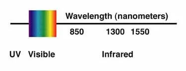
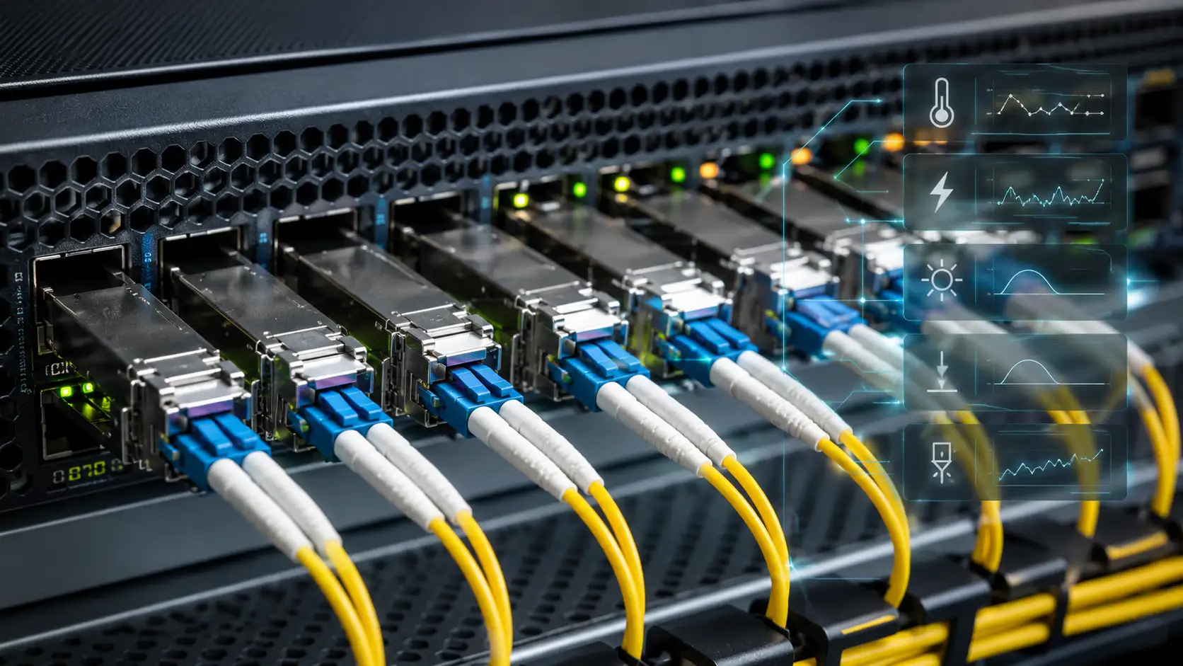
A spine-leaf fabric needs far more inter-switch links than a three-tier design, so the physical layer deserves the same attention as the switching layer. For short links inside or between adjacent racks, direct-attach (DAC) or active optical (AOC) cables are usually the most economical choice. For longer runs between rows, rooms or data halls, you will reach for fiber and pluggable optical transceivers. Match each transceiver to its job by distance, fiber type and port speed: 100G QSFP28 modules are a common leaf-to-spine uplink today, with 40G QSFP options still widely deployed in existing fabrics and easy to break out to lower speeds. To keep high uplink counts manageable, most data centers standardize on structured MPO/MTP trunk cabling rather than hand-running individual jumpers between racks.
Choosing the glass itself comes down to distance and budget: OM4 multimode is cost-effective for short data-hall runs, while OS2 single-mode covers the longer or future-proofed links. When you plan this layer, confirm link distance, cable pathway capacity, fiber and connector type, transceiver compatibility (including wavelength, FEC and breakout support), and the upgrade path to higher speeds. Ignoring cabling complexity is one of the most common ways a spine-leaf project slips - not because the logical design is wrong, but because mismatched optics, an exhausted cable tray or an MPO polarity mistake stalls the install and forces re-ordering.

Step 5: Make the fabric manageable from day one
As switch, link and policy counts climb, manual configuration becomes the main source of outages. Before selecting hardware, check that the platform supports configuration templates, API access, telemetry, fabric validation, centralized monitoring, change control and role-based access. A fast fabric that the team cannot monitor, troubleshoot or upgrade safely is not actually a good fabric.
Sizing by Use Case: Three Reference Points
Spine-leaf is useful wherever performance, scale and predictable flows matter, but the right oversubscription and optics differ sharply by workload. The table below maps three common environments to their network priorities.
| Environment | Network requirement | Design emphasis |
|---|---|---|
| Small / enterprise data center | Steady east-west, moderate growth | Moderate oversubscription, 25G servers with 100G uplinks, structured trunk cabling |
| Enterprise private cloud | Tenant isolation, workload mobility | Layer 3 underlay plus VXLAN/EVPN overlay, dual-homed leaves via EVPN multihoming |
| AI / HPC / distributed storage | High throughput, low latency between nodes | Low or non-blocking oversubscription, high-speed optics, possible super-spine for multiple pods |
Cloud platforms, virtualization clusters, container environments, large-scale analytics and financial trading infrastructure all generate heavy east-west traffic and all benefit from the same predictable fabric - they simply sit at different points on the oversubscription and bandwidth curve. Larger AI and HPC deployments may also add a super-spine layer to interconnect multiple fabric pods.
Key Benefits, Stated Concretely
The advantages of spine-leaf are easy to list and worth grounding in why they happen:
- Predictable low latency, because every cross-rack flow crosses the same hop count rather than a variable path through a hierarchy.
- Better bandwidth utilization, because ECMP keeps every uplink active instead of reserving half of them as idle backups.
- Easier horizontal scaling: add leaves for more server ports, add spines for more cross-fabric bandwidth - as long as uplink capacity was planned in.
- Improved resilience, because the loss of one spine or one uplink simply reroutes traffic over the remaining equal-cost paths. This is also why two spines is the practical minimum; a single spine is a single point of failure.
- Better fit for automation, because a repeatable, uniform structure is far easier to template and validate than a hand-tuned legacy topology.
When Spine-Leaf May Not Be the Best Fit
Spine-leaf is powerful, not universal. It can be more complexity and cost than the situation warrants when the environment is small and unlikely to grow, when traffic is mostly simple north-south, when the team lacks Layer 3 routing or fabric experience, when cable pathways are already constrained, when the budget cannot absorb the extra optics and inter-switch links, or when a simpler collapsed-core design genuinely meets the requirement. For a small server room, a well-built two-switch or collapsed-core setup may be enough. For a growing data center, cloud platform or AI cluster, spine-leaf is usually the stronger long-term foundation. Match the design to the business need, not to a trend.
Common Mistakes to Avoid - and What They Cost
- Designing only for today's port count. Consume every leaf uplink on day one and the next expansion becomes a disruptive, downtime-heavy change.
- Underestimating cable and optics cost. The switch price is only part of the bill; transceivers, DACs, AOCs, fiber trunks, patch panels and installation labor can swing the total significantly and are the line items most often left out of early budgets.
- Ignoring oversubscription. A design that looks scalable can still throttle real workloads if uplink bandwidth is too low for the traffic pattern.
- Treating VXLAN/EVPN as a feature checkbox. The overlay reshapes routing, segmentation and troubleshooting; deploy it at scale without understanding underlay/overlay interaction and operations get painful fast.
- Forgetting operations. Without monitoring, visibility and documentation built in from the start, even a high-performance fabric becomes risky to change.
How to Choose Switches, Optics and Cables
Evaluate the whole system, not isolated spec sheets. For leaf switches, weigh server-facing port speed, uplink capacity, buffer sizing, support for MLAG or EVPN multihoming, VXLAN/EVPN capability, automation and telemetry features, and power and airflow direction. For spine switches, weigh high-speed port density, non-blocking forwarding capacity, routing scale, ECMP support, reliability and a clear upgrade path to faster optics. For optics and cables, weigh link distance, fiber type, transceiver form factor, power consumption, vendor compatibility, temperature range, breakout support and long-term availability. A reliable fabric depends on both the switching platform and the physical layer; poor cable planning or incompatible optics can delay deployment even when the logical design is flawless.
FAQ
Q: Is spine-leaf Layer 2 or Layer 3?
A: Modern spine-leaf fabrics are Layer 3 between leaf and spine - every leaf-to-spine link is a routed interface, and ECMP spreads traffic across them. Layer 2 services, when needed, are delivered as an overlay (typically VXLAN with EVPN) on top of that routed underlay, not by extending Layer 2 across the physical fabric.
Q: How many spine switches do I need?
A: At least two, so the failure of one spine does not take down the fabric. Beyond that, the count depends on your oversubscription target: a fully non-blocking design needs as many spines as each leaf has uplink ports, while a 3:1 ratio on a leaf using four active uplinks needs four spines.
Q: What is the difference between leaf-spine and spine-leaf?
A: None - they are two names for the same two-tier topology. "Spine-and-leaf," "leaf-spine" and "spine-leaf" all describe a design where every leaf connects to every spine.
Q: Does spine-leaf require VXLAN/EVPN?
A: No. If all inter-leaf traffic is pure routed Layer 3 and you never need to stretch a Layer 2 domain between racks, a plain leaf-spine fabric with eBGP and no overlay works well and is simpler to run. VXLAN/EVPN is needed for Layer 2 adjacency across racks, workload mobility between leaves, or multi-tenant isolation.
Q: Is spine-leaf suitable for small data centers?
A: It can be, but it is not always the most economical choice. A small site with mostly north-south traffic and little expected growth may be better served by a collapsed-core or two-switch design. Spine-leaf earns its extra cabling and optics cost when the environment is growing, runs distributed workloads, or needs predictable east-west performance.
Conclusion
Spine-leaf architecture gives modern data centers scalable bandwidth, predictable latency and a structure built for heavy east-west traffic, and it scales out by adding switches rather than replacing them. But its value depends entirely on planning. Before selecting hardware, settle the port count, uplink capacity, oversubscription target, underlay and overlay decisions, and - just as importantly - the cabling and optics plan that ties the whole fabric together. If your data center is growing, running distributed workloads or preparing for higher-speed server connectivity, the next step is to translate those workload requirements into a concrete fabric design, complete with switches, transceivers, cables and the management tooling to keep it healthy.