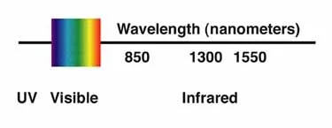
850nm, 1310nm and 1550nm are the three standard fiber optic wavelengths because each one lines up with a low-loss transmission window in glass fiber and is backed by mature lasers, detectors, transceivers and test gear. The quick rule most engineers use: pick 850nm for short multimode links inside a building or data center, 1310nm for single-mode links up to around 10 km, and 1550nm for long-haul, amplified or DWDM systems. The rest of this guide explains why those windows exist, what each wavelength actually costs you in attenuation, and how to match a wavelength to your fiber, optics, distance and test plan.
Wavelength is never a standalone choice. It is locked to the fiber type and the optical module, so the real goal is to choose a complete combination - fiber, transceiver, connector and link budget - rather than a number in isolation.
What Is a Fiber Optic Wavelength?
A wavelength is the spacing between repeating points of a light wave, measured in nanometers (nm) in fiber optics. The light sits in the near-infrared band and is invisible to the eye, which is why a live fiber can carry significant optical power with nothing showing at the connector - and why you should never look into a powered fiber.
When a link is described as "850nm," "1310nm" or "1550nm," that figure is the nominal center wavelength of the transmitted signal. Wavelength matters because it drives attenuation, chromatic dispersion, usable distance, fiber-type compatibility, transceiver design, WDM channel planning, and how the link is tested.

Why Fiber Optics Use 850nm, 1310nm and 1550nm
Glass does not attenuate every wavelength equally. Loss is dominated by Rayleigh scattering, which falls off sharply as wavelength rises (roughly with the inverse fourth power of wavelength), plus absorption peaks - historically a strong water/OH⁻ peak near 1383nm. The three classic windows sit in the low-loss valleys between those peaks, which is the core reason they became standard.
These windows also map onto the named optical bands used across the industry. 1310nm sits in the O-band (original, roughly 1260–1360nm), while 1550nm sits in the C-band (conventional, roughly 1530–1565nm), with the S-, E- and L-bands filling the gaps. If you want the full band plan, our overview of fiber optic wavelength bands and optical transmission windows walks through each one.
Just as important is the ecosystem. The industry built complete hardware around these three points: VCSELs and LEDs at 850nm, Fabry-Perot and DFB lasers at 1310nm and 1550nm, matching photodiodes, transceivers, WDM filters and test instruments. That mature supply chain is a big part of why the three windows have stayed dominant for decades.
850nm vs 1310nm vs 1550nm
| Wavelength | Usual fiber | Typical attenuation* | Common optics / standards | Typical reach | Best for | Main limitation |
|---|---|---|---|---|---|---|
| 850nm | Multimode (OM3/OM4/OM5) | ~2.5–3.5 dB/km | VCSEL SFP+/QSFP, 10GBASE-SR, 40G/100G-SR4 | Tens to a few hundred metres | Cost-efficient short links | Short distance, modal bandwidth limits |
| 1310nm | Single-mode (OS2); legacy MM testing | ~0.32–0.4 dB/km (single-mode) | DFB SFP/SFP+, 1000BASE-LX, 10GBASE-LR, 100G-LR4 | ~2–10+ km | Balanced single-mode reach | Higher loss than 1550nm over long spans |
| 1550nm | Single-mode (OS2) | ~0.18–0.25 dB/km | 10GBASE-ER/ZR, DWDM/coherent, EDFA-amplified | 40–80+ km, hundreds of km amplified | Long-haul and WDM capacity | Bend-sensitive; nonlinearities at high power |
*Typical figures. Actual loss depends on the fiber grade and the applicable standard.
Treat this table as a starting point. The final choice should follow the fiber specification, the transceiver datasheet, the network standard and the link budget.
Typical Attenuation by Wavelength
Attenuation is the single most useful number for planning, so here are representative values. For multimode fiber, loss is roughly 3 dB/km at 850nm and about 1 dB/km at 1300/1310nm, with TIA-568 setting maximums near 3.5 and 1.5 dB/km. For single-mode fiber, loss is around 0.32–0.4 dB/km at 1310nm and 0.18–0.25 dB/km at 1550nm, and premium low-loss fibers reach below 0.17 dB/km at 1550nm. These line up with the typical loss figures published by The Fiber Optic Association.
| Fiber and wavelength | Typical attenuation | Notes |
|---|---|---|
| Multimode @ 850nm | ~2.5–3.5 dB/km | TIA-568 maximum near 3.5 dB/km |
| Multimode @ 1300nm | ~0.7–1.5 dB/km | Now mainly a test / legacy wavelength |
| Single-mode @ 1310nm | ~0.32–0.4 dB/km | O-band, near the zero-dispersion region |
| Single-mode @ 1550nm | ~0.18–0.25 dB/km | C-band; ultra-low-loss fiber below 0.17 dB/km |
Why this matters: over 100 m the difference between wavelengths is trivial, but over 80 km it decides whether the link closes at all. That gap is the central reason 1550nm dominates long-distance design while 850nm stays in the data center.

850nm: Short-Reach Multimode Links
850nm is the multimode workhorse. It runs on OM3, OM4 and OM5 fiber with low-cost VCSEL transceivers, which is why it dominates inside data centers and buildings.
Where it fits. Data center switch-to-server and leaf-spine links, short Ethernet runs, and high-density structured cabling. A common real example is a 100GBASE-SR4 link over OM4 multimode patch cords at up to roughly 100 m, or 10GBASE-SR over OM3/OM4 for shorter hops. These pair with multimode SFP+, QSFP and QSFP28 modules.
- Best fit: short, dense, cost-sensitive links where fiber runs are well under a few hundred metres.
- Avoid when: the span needs single-mode reach - pushing 850nm past its budget causes bit errors, not just thinner margin.
- Check before use: fiber grade (OM3 vs OM4 vs OM5), connector type, and the module's supported distance at your data rate. At high speeds it is modal bandwidth, not attenuation, that caps the 850nm distance.
1310nm: Balanced Single-Mode Links
1310nm is the default for single-mode links that do not need DWDM capacity or 1550nm reach. It sits in the O-band, near the zero-dispersion region of standard single-mode fiber, which keeps chromatic dispersion low and makes it forgiving over moderate distances. That zero-dispersion-near-1310nm behavior is exactly what ITU-T G.652 specifies for standard single-mode fiber.
Where it fits. Enterprise and campus backbones, metro access, and medium-distance point-to-point links on OS2 single-mode patch cords. Typical optics are 1000BASE-LX, 10GBASE-LR (about 10 km) and 100GBASE-LR4 - the "LR / long-reach" family.
1310nm vs 1550nm, briefly. 1310nm wins on dispersion and component cost for moderate spans; 1550nm wins on attenuation and amplifier support for long spans. If your link is under roughly 10 km and you are not multiplexing many channels, 1310nm is usually the simpler and cheaper choice.
Is 1310nm single-mode or multimode? In modern design it is a single-mode wavelength. You will still see 1300/1310nm in multimode testing and legacy multimode contexts, which is why you should read the full system specification rather than judge by wavelength alone.
- Best fit: single-mode links up to roughly 10 km without amplification.
- Avoid when: you need 40 km or more unamplified, or high-channel-count DWDM.
- Check before use: that both ends are single-mode, that the connector and polish match, and that the reach class (for example LR vs ER) covers your distance.
1550nm: Low Loss for Long-Haul and WDM
1550nm is the long-distance and high-capacity wavelength. Attenuation in silica is at its practical minimum here, so every kilometre costs less optical power - decisive over tens or hundreds of kilometres.
Two things make 1550nm special. First, low loss stretches the link budget for long spans. Second, it sits in the C-band, where erbium-doped fiber amplifiers (EDFAs) operate, so signals can be boosted optically without converting back to electronics. Together these enable 10GBASE-ER (about 40 km), 10GBASE-ZR (about 80 km) and long-haul coherent systems.
1550nm and WDM. Wavelength division multiplexing sends many channels down one fiber at different wavelengths. Dense WDM (DWDM) packs dozens of closely spaced channels around the C-band, on the grid anchored at 193.1 THz (about 1552.52 nm) defined by ITU-T G.694.1. That is why 1550nm is not merely a "low-loss" wavelength but the backbone of high-capacity transport. For multi-channel links, our DWDM mux/demux modules handle the wavelength combining and splitting.
- Best fit: long-haul, metro transport, amplified links and DWDM capacity.
- Avoid when: a short link would be cheaper on 850nm or 1310nm. 1550nm optics and amplifiers cost more, and high launch power can trigger nonlinear effects.
- Check before use: launch power versus receiver overload, dispersion over long spans, and whether the route is C-band only or C+L.
Fiber Optic Wavelength Selection Chart
Use this matrix to go from a scenario to a starting configuration, then confirm against datasheets and your link budget.
| Scenario | Recommended wavelength | Fiber | Typical optics | Watch out for |
|---|---|---|---|---|
| Data center short reach (≤100–150 m) | 850nm | OM4 / OM5 multimode | SR / SR4 (40G / 100G) | Modal bandwidth at high speed |
| In-building or campus backbone | 1310nm | OS2 single-mode | LX / LR | Connector loss budget |
| Building-to-building / metro access (≤10 km) | 1310nm | OS2 single-mode | 10G LR / 100G LR4 | Total link loss |
| Long span, no amplification (40–80 km) | 1550nm | OS2 single-mode | ER / ZR | Power budget, dispersion |
| Long-haul / high capacity | 1550nm (C-band) | OS2 single-mode | DWDM + EDFA / coherent | Channel plan, nonlinear effects |
| Bidirectional single-fiber PON | 1490/1310 (GPON) or 1577/1270 (XGS-PON) | OS2 single-mode | BiDi / PON optics | Coexistence filtering |

How to Choose the Right Fiber Optic Wavelength
Wavelength is a system-design decision, not just physics. Work through five checks.
1. Match the fiber type
Multimode fiber (OM3/OM4/OM5) points to 850nm for modern short reach. Single-mode fiber (OS2) points to 1310nm for moderate distance and 1550nm for long or WDM links. If you are unsure which fiber a route uses, this breakdown of how single-mode and multimode fiber differ in distance and speed will help you decide.
2. Match the distance
Short hops in a rack or room are fine on 850nm multimode and cheapest there. Building-to-building, campus, metro and access links suit 1310nm single-mode. Very long, amplified or high-capacity routes call for 1550nm.
3. Match the transceiver
Never choose a wavelength apart from the optical module. A transceiver is built for a specific wavelength, fiber type and reach, and the cable has to match it. You can browse SFP optical transceivers by wavelength and reach to pair correctly. Always confirm wavelength, fiber type, connector interface, maximum reach, transmit power, receiver sensitivity, link budget and data rate.
4. Check the link budget
The link budget compares transmitter power against every loss in the path: fiber attenuation, connectors, splices, splitters, patch panels, bends and aging margin. A low-attenuation wavelength can still fail if connector or splitter loss eats the budget.
5. Plan the testing
Test at the operating wavelength wherever possible. Multimode is tested at 850nm, and sometimes at 1300nm to reveal stress; single-mode is tested at 1310nm and 1550nm, with 1625nm sometimes added for maintenance and bend detection. Testing at the wrong wavelength can hide real faults or produce misleading results.
When Not to Use Each Wavelength
- Don't use 850nm when the link needs single-mode reach - it is a short-reach multimode wavelength and will not close a long span.
- Don't use 1310nm when you need 40 km or more unamplified, or dense DWDM capacity; 1550nm is built for that.
- Don't default to 1550nm for a short in-building link; the optics and amplifiers cost more, and high power on a short span can add nonlinear penalties for no benefit.
- Don't mix a multimode module with single-mode fiber (or the reverse) - core size, launch condition and reach differ, and the link can fail outright.
Common Mistakes About Fiber Optic Wavelengths
Longer is not always better
Longer wavelengths scatter less, but absorption, dispersion, component cost, nonlinear effects and system standards all matter. 1550nm wins on balance for long links, not because longer is automatically better.
Treating multimode and single-mode as interchangeable
An 850nm multimode module is not a drop-in for a 1310nm single-mode module. Core size, launch conditions and distance limits differ, so the wrong pairing causes high loss or a dead link.
Ignoring the application
A data center, an FTTH access network, a metro ring and a DWDM long-haul route all use fiber, but each prioritizes something different - cost, reach, density, capacity or amplification - so each uses a different wavelength strategy.
Testing at only one wavelength
A link can behave differently across wavelengths. Single-wavelength testing can miss bending loss or wavelength-specific problems, so test to the project standard and the equipment requirement.
FAQ About Fiber Optic Wavelengths
Q: Why are 850nm, 1310nm and 1550nm common in fiber optics?
A: They sit in the low-loss windows of glass fiber and are supported by mature lasers, detectors, transceivers and test equipment.
Q: Which wavelength is best for multimode fiber?
A: 850nm, especially on OM3, OM4 and OM5 in data centers and enterprise LANs.
Q: Which wavelength is best for single-mode fiber?
A: Both 1310nm and 1550nm. 1310nm suits moderate distances; 1550nm suits long-distance and WDM applications.
Q: Is 1310nm better than 1550nm?
A: Neither is universally better. 1310nm offers lower dispersion and lower-cost optics for moderate spans; 1550nm offers lower attenuation and amplifier support for long or WDM links.
Q: Should I run OTDR tests at 1310nm or 1550nm?
A: For single-mode, test both. The two wavelengths reveal different things, and 1550nm (or 1625nm) is more sensitive to bends and stress, so a fiber can pass at 1310nm yet fail at 1550nm or 1625nm at a stress point.
Q: Why does 1550nm expose bending loss more than 1310nm?
A: Longer wavelengths radiate more easily out of a bent core, so macrobends and stress points appear as extra loss at 1550nm and 1625nm before they show up at 1310nm. That is why 1625nm is a common maintenance and monitoring wavelength.
Q: Why do I also see 1490nm, 1270nm, 1577nm or 1625nm?
A: These appear in PON and in maintenance. GPON uses 1490nm downstream and 1310nm upstream, with 1550nm for an RF video overlay; XGS-PON uses 1577nm downstream and 1270nm upstream so it can coexist with GPON on the same fiber, per the ITU-T G.984 and G.9807.1 standards. 1625nm and 1650nm are used for live-fiber monitoring.
Q: Can 850nm work on single-mode fiber?
A: Not in standard design - 850nm is a multimode wavelength. Follow the transceiver and cable specifications.
Q: What wavelength should I use for fiber testing?
A: Whatever the fiber type, system design and acceptance standard require: multimode at 850nm (and 1300nm), single-mode at 1310nm and 1550nm.
Key Takeaways
850nm, 1310nm and 1550nm became standard because each sits in a low-loss window with mature components and established standards. Use 850nm for short multimode links, 1310nm for single-mode access and metro up to about 10 km, and 1550nm for long-distance, amplified and DWDM networks. Above all, never pick a wavelength alone - match it to the fiber type, transceiver, distance, link budget and test plan. That is how you build a reliable optical fiber link.