When a Fortune 500 financial services provider needed to scale their data center from 10G to 100G connectivity, traditional fiber termination methods would have required weeks of manual splicing and testing. Instead, their infrastructure team deployed pre-terminated mtp trunk cables, completing the migration in 72 hours with zero signal loss. This scenario illustrates why understanding mtp trunk mechanics has become essential for modern network infrastructure-these high-density multi-fiber assemblies compress what once took dozens of individual connections into a single, reliable interface that supports speeds from 40G through 400G and beyond.
Understanding Network Density Demands Across Different Scales
Data centers face a fundamental challenge: exponentially growing bandwidth requirements colliding with fixed physical space. A typical hyperscale facility may need to support 10,000+ server connections within racks measuring just 42U in height, while enterprise edge deployments must pack maximum capacity into equipment closets smaller than a storage room.
The physics of traditional duplex fiber creates an unavoidable bottleneck. Each duplex connection handles only two fibers, requiring separate connectors, patch cords, and panel space for every circuit. When organizations scale to hundreds or thousands of connections, this approach consumes massive amounts of rack space, increases cable congestion, and multiplies potential failure points.
Multi-fiber push-on technology addresses these constraints through parallel fiber transmission. Rather than routing signals through individual fiber pairs, mtp trunk cables integrate multiple optical fibers-typically 8, 12, 24, or up to 144 strands-into one compact connector interface. This architectural shift delivers density improvements of 6x to 12x compared to duplex connections.
The implications extend beyond space savings. Pre-terminated assemblies arrive from manufacturers already tested and certified, eliminating field termination errors that plague on-site fusion splicing. Installation teams can deploy an entire backbone link in minutes rather than hours, and maintenance windows shrink dramatically when troubleshooting or upgrades require only connector changes instead of re-termination.
Real-World Impact at Mid-Market Scale
A 300-employee SaaS company operating four regional data centers recently documented their migration from LC duplex to MTP infrastructure. Their network team reported 67% reduction in cable pathway congestion, 40% faster deployment times for new equipment, and-most critically for their budget-a 35% decrease in annual cabling maintenance costs. The project's success hinged on selecting appropriate polarity methods and correctly matching trunk types to their cassette modules, decisions that would have derailed the deployment if mishandled.
Core Architecture: How Multi-Fiber Arrays Enable Parallel Transmission
At its foundation, an MTP MTP Cable- a core type of MTP Cable with MTP connectors on both ends-consists of precision-aligned optical fibers embedded within a ribbon structure, terminated on both ends with multi-fiber connectors. The connector itself-whether the proprietary MTP brand from US Conec or generic MPO variants-features a rectangular ferrule with either 8 or 12 fiber holes arranged in a single row.
Physical Alignment Mechanism
Proper fiber alignment requires physical pins that ensure transmit and receive fibers mate correctly between connectors. MTP male connectors contain two precision metal pins, while female connectors feature corresponding holes to accept these alignment guides. This gender pairing is non-negotiable: attempting to mate two female connectors produces physical fit but zero optical transmission, a common installation mistake that appears successful until testing reveals complete signal failure.
Each fiber position within the connector receives a numerical designation-Position 1 through 12 for standard 12-fiber arrays. A white dot on the connector housing marks the Position 1 location, providing visual confirmation of orientation during installation. This positional precision matters because parallel optics applications transmit on specific fiber lanes while receiving on others, and any misalignment between transmit-receive pairs results in dark channels or complete link failure.
Connector Key Orientation
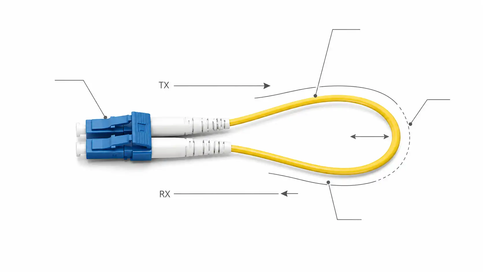
The connector housing includes a protruding key on one side, creating the industry-standard terms "key up" and "key down" to describe connector orientation. When mating connectors, key position determines whether fiber positions map straight-through (Position 1 to Position 1) or flip (Position 1 to Position 12). This mechanical feature becomes the foundation for polarity management-the most complex and frequently misunderstood aspect of MTP deployment.
Cable Construction Variants
Trunk cables employ different internal structures depending on application requirements:
Ribbon fiber construction: All fibers aligned in a flat ribbon, optimal for high-density backbones between equipment rooms
Round fiber bundles: Individual fibers within a circular jacket, providing greater flexibility for routing through tight pathways
Micro-distribution designs: Ultra-compact outer diameters (typically 6.5-6.8mm) that maximize airflow space in congested cable trays
Armored variants: Additional protective layers for outdoor installations or harsh industrial environments
Multimode fiber types (OM3, OM4, OM5) support shorter distances up to 400 meters for 100G applications, while singlemode (OS2) extends reach beyond 10 kilometers with proper optics. The fiber grade selection directly impacts power budget calculations and maximum transmission distance for specific protocol requirements.

Three Polarity Methods: Maintaining Transmit-Receive Alignment
Polarity represents the critical challenge in MTP systems: ensuring every transmitter at one end connects to its corresponding receiver at the opposite end. Unlike duplex connections where a simple A-to-B crossover handles this automatically, multi-fiber arrays require systematic approaches to maintain correct fiber position mapping across trunk cables, patch panels, and equipment connections.
Industry standards define three distinct methods-A, B, and C-each employing different combinations of trunk cable types, adapter orientations, and patch cord configurations. Once a polarity method is selected for a deployment, all components throughout the channel must conform to that method's specifications. Mixing methods within a single link guarantees connectivity failures.
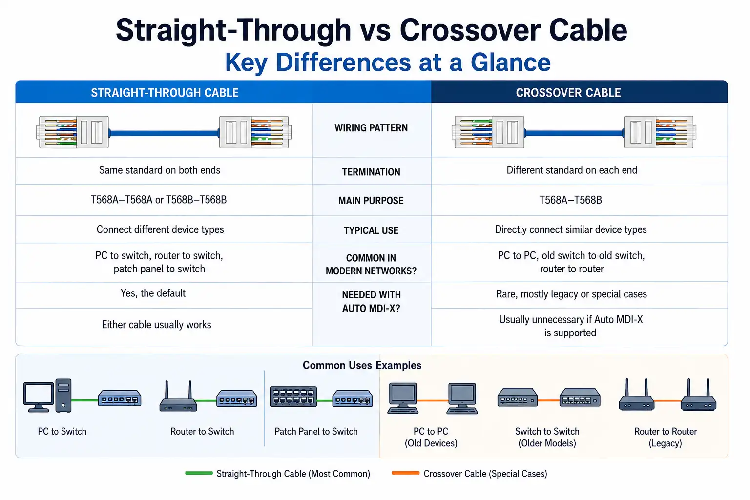
Method A: Straight-Through Trunks with Polarity Flip in Patch Cords
Method A utilizes Type A trunk cables where fiber positions remain consistent end-to-end. Position 1 at the near end connects to Position 1 at the far end, Position 12 to Position 12, and so forth. To achieve this straight-through mapping, one connector features key-up orientation while the opposite end is key-down.
The polarity flip required for transmit-receive matching occurs in the patch cords. Standard A-to-B crossover patch cables connect equipment on one end, while A-to-A straight-through patch cables complete the circuit on the opposite end. This arrangement maintains proper Tx-to-Rx alignment despite the straight-through trunk.
Implementation Considerations:
Method A offers simplicity during backbone installation since all trunk cables follow identical construction. However, operations teams must manage two different patch cord types and understand which belongs at each end of the link. Documentation becomes essential to prevent technicians from swapping patch cord types during routine maintenance, an error that instantly breaks connectivity.
This method also presents challenges for migration paths. Organizations cannot easily convert from duplex cassette-based connections to direct parallel optics without replacing trunks or introducing conversion modules, adding cost and complexity to technology upgrades.
Method B: Reversed Trunks with Universal Patch Cords
Method B inverts the approach by implementing the polarity flip within the trunk cable itself. Type B cables reverse fiber positions end-to-end: Position 1 at the near end connects to Position 12 at the far end, Position 2 to Position 11, and the pattern continues through the entire array. Both connector ends feature key-up orientation, creating the distinctive key-up-to-key-up configuration.
With polarity handled by the trunk, both equipment connections use identical A-to-B crossover patch cords. This standardization dramatically simplifies operations: IT teams stock a single patch cord type and technicians can grab any patch cord for any port without risk of polarity errors.
Professional Services Deployment Example
A legal firm with 150 attorneys across eight offices implemented Method B for their disaster recovery infrastructure connecting primary and secondary data centers. Their IT director cited patch cord standardization as the decisive factor-during emergency failover procedures, any available technician could execute connectivity changes without consulting documentation or verifying cord types, reducing recovery time objectives by an estimated 30%.
Method B's universal components also enable seamless migration between connection types. The same trunk cables support both duplex applications (via cassettes) and direct parallel optics connections (via adapters), providing technology flexibility as bandwidth needs evolve.
Method C: Pair-Flipped Configuration for Duplex Breakouts
Method C targets specific duplex applications where MTP trunks must connect to equipment via standard LC or SC connectors. The trunk cable flips adjacent fiber pairs: Position 1 maps to Position 2, Position 2 to Position 1, Position 3 to Position 4, and so on through the array. Like Type A, the cable features one key-up and one key-down connector.
This pair-flipping works perfectly for duplex circuits where Tx-Rx crossover occurs naturally within each fiber pair. However, Method C proves incompatible with parallel optics applications that require specific lane assignments for transmit and receive functions. The industry generally discourages Method C for new deployments due to its limited upgrade path and potential for configuration confusion.
Practical Selection Guidance
For greenfield data center projects, Method B consistently emerges as the recommended approach. Its operational simplicity, universal components, and migration flexibility outweigh any minor differences in initial trunk cable costs. Method A remains viable for environments with mature documentation systems and experienced installation teams who understand the patch cord management requirements. Method C should be reserved exclusively for legacy installations or specialized duplex-only applications with no future parallel optics requirements.
Installation Mechanics: From Cable Pull to Signal Verification
Deploying mtp trunk infrastructure follows a systematic workflow that balances speed advantages against precision requirements. Unlike field-terminated fiber where mistakes get corrected through re-polishing or re-splicing, pre-terminated assemblies offer limited flexibility once installed-connector damage or incorrect polarity selections often necessitate complete cable replacement.
Pre-Installation Planning Phase
Successful installations begin with thorough pathway surveys and precise measurements. Cable lengths must account for slack management, vertical rise, and sufficient service loop at each end-typically 1-2 meters beyond the direct distance measurement. Over-ordering by 10-15% prevents situations where cables stretch taut or require mid-span splicing to extend reach.
Network teams map polarity requirements end-to-end before ordering cables. This includes verifying equipment port gender (always male/pinned on active transceivers), cassette adapter types (key-up-to-key-down or key-up-to-key-up), and patch cord inventory (A-to-A versus A-to-B). A single mismatch anywhere in the channel blocks installation progress until replacement components arrive.
Cable jacket ratings must match installation environment codes. Plenum-rated (OFNP) cables meet stringent fire safety requirements for air-handling spaces above drop ceilings, while riser-rated (OFNR) variants suffice for vertical pathways between floors. Outdoor runs require weatherproofing with armored jackets or protective conduit.
Physical Installation Execution
The MTP Cable arrives from manufacturers with protective boots or pulling grips attached to connector ends, preventing ferrule damage during installation. These protective elements must remain in place until cables reach their final positions-removing them prematurely invites connector contamination that degrades optical performance.
For long horizontal runs, cable managers employ fish tape or pull strings to guide cables through conduits and overhead trays. Pulling tension should never exceed the manufacturer's specified maximum (typically 100-200 Newtons for standard cables), and bend radius must remain at least 10x the cable diameter during installation, relaxing to 5x for static installations after securing.
Vertical riser installations require support every 1-1.5 meters to prevent cable jacket stress from the fiber bundle's weight. J-hooks, Velcro wraps, or cable ties attach cables to rack uprights or wall channels without over-compressing the jacket-excessive tightening can deform the fiber ribbon and increase insertion loss.
Connector Protection and Cleaning
Once cables reach equipment locations, technicians remove protective boots and immediately inspect connector ferrules for contamination. Even microscopic particles or fingerprint oils on fiber end-faces cause insertion loss and reflection that degrade high-speed signal integrity. Professional installations employ specialized MTP cleaning cassettes or lint-free wipes with isopropyl alcohol to ensure optical-grade cleanliness.
The 12 or 8 individual fiber end-faces within an MTP ferrule create a cleaning challenge-standard duplex techniques don't transfer well to multi-fiber arrays. Inspection requires dedicated MTP microscopes with sufficient magnification to examine all fibers simultaneously. Any visible contamination mandates re-cleaning until inspection passes.
Connectivity Sequence and Testing
Trunk cables typically connect to patch panel cassettes or adapter panels depending on application type. For cassette-based duplex installations, the MTP trunk plugs into the cassette's rear port while equipment patch cords attach to front-facing LC or SC ports. Parallel optics deployments use MTP adapter panels that mate trunk connectors directly to MTP patch cords connecting transceiver modules.
Connection technique matters significantly. Unlike duplex connectors that provide tactile feedback when seated, MTP connectors require specific insertion pressure and a distinct click to achieve proper mating. Insufficient insertion force leaves connectors partially seated with air gaps between ferrules, causing catastrophic signal loss. Over-insertion can damage alignment pins or crack ferrules.
Testing begins with simple continuity checks using visual fault locators-red laser light sources that illuminate fiber paths and quickly identify breaks, severe bends, or connection failures. Next, optical loss test sets (OLTS) measure insertion loss across each fiber channel, comparing results against manufacturer specifications and IEEE standards. Typical acceptable insertion loss ranges from 0.35dB to 0.75dB depending on connector type and fiber grade.
Bi-directional loss testing provides the most accurate results, measuring from both ends of each fiber pair to detect directional anomalies caused by contamination or physical defects. Professional installations document all test results, creating baseline performance records that facilitate future troubleshooting when network issues arise.
B2B SaaS Company Case Study
A cloud services provider specializing in HIPAA-compliant healthcare data storage deployed 72 MTP trunks across their Tier III data center. Their structured approach included detailed cable management drawings, color-coded identification labels, and comprehensive test documentation. During Year 2 operations, this preparation paid dividends when a partial fiber break occurred in one trunk-having precise test baselines allowed the team to isolate the fault to a specific 8-fiber segment within 15 minutes, versus the hours potentially spent on untested infrastructure.

Differentiating Trunk Cables from Breakout Assemblies
The mtp trunk category includes two functionally distinct product types that serve different connectivity needs: true trunk cables with MTP connectors on both ends, and breakout cables that transition from MTP to duplex connectors. Understanding which type suits specific applications prevents ordering errors and deployment delays.
Trunk Cables: Backbone Connectivity
Pure trunk cables feature identical MTP connector configurations on both ends-either both female, both male, or occasionally one of each depending on application. These assemblies support high-bandwidth parallel transmission between equipment or interconnect modules across distribution frames. The fiber count remains constant end-to-end: a 24-fiber trunk has 24 fibers throughout its length, terminated to two 12-fiber MTP connectors or one 24-fiber connector per end.
Trunk applications include:
Main distribution area links: Connecting primary patch panels to zone distribution cabinets
Direct switch-to-switch connectivity: High-speed backplane connections in spine-leaf architectures
Storage network fabrics: Fibre Channel or NVMe-oF interconnects between storage arrays and compute clusters
Inter-building campus links: Outdoor-rated trunks spanning up to several kilometers between facilities
The parallel transmission capability enables impressive density: a single 12-fiber trunk supports four 10G connections, one 40G connection, or twelve 100G connections when using appropriate transceiver optics. This efficiency makes trunks ideal for structured cabling deployments where one-time installation of fixed infrastructure supports multiple technology generations through front-end patch cord changes.
Breakout Cables: Density-to-Duplex Transitions
Breakout cables employ an MTP connector on one end while fanning out to multiple duplex connectors (typically LC) on the opposite end. A common 12-fiber breakout has one MTP-12 connector transitioning to six duplex LC pairs, while 24-fiber variants break out to twelve duplex connections.
These assemblies serve specific high-speed-to-lower-speed conversion scenarios:
100G to 4x25G breakout: Single QSFP28 100G port connecting to four SFP28 25G server NICs
40G to 4x10G disaggregation: QSFP+ switch port supporting four 10G copper switches or servers
200G to 8x25G distribution: QSFP56 port breaking out to eight edge devices
Breakout cables eliminate the need for intermediate cassettes in direct equipment connections, reducing components and potential failure points. However, they sacrifice the flexibility and scalability benefits of structured cabling-changing port assignments or upgrading to different speeds often requires replacing the entire breakout assembly.
SMB Deployment Scenario
A 75-person architectural firm upgraded their headquarters network from 1G to 10G while preparing for future 25G server connections. They chose MTP trunk infrastructure connecting cassettes at distribution panels, enabling them to deploy 10G SFP+ patch cords immediately while maintaining upgrade paths. A comparable breakout-based design would have locked them into specific port configurations with limited flexibility for their anticipated growth to 100G backbone links within three years.
Transmission Performance Characteristics
MTP trunk systems achieve their density advantages without compromising signal quality, but only when properly specified and installed. Understanding the optical performance parameters helps network engineers make appropriate design decisions for their distance and power budget requirements.
Insertion Loss Budgets
MTP trunk cables deliver consistent signal propagation with low insertion loss and superior return characteristics while operating within high-density capacity. Standard MTP connectors typically specify maximum insertion loss of 0.5dB per mated connector pair, while elite or premium variants reduce this to 0.35dB or lower through tighter manufacturing tolerances.
In a typical structured cabling link, total insertion loss accumulates from multiple sources:
Trunk cable: 0.4-0.6dB per connection (connector pair + fiber)
Cassette internal connections: 0.3-0.5dB
Patch cords: 0.3-0.4dB per connection
Additional fiber loss: ~0.3dB per 100 meters (OM4 multimode)
A complete channel might total 2.0-3.0dB insertion loss, well within the power budgets for 100G-SR4 optics (typically 4.5dB) or 40G-SR4 (1.9dB minimum). However, accumulating excessive losses through contaminated connectors, damaged fiber, or excessive bend radius violations can push channels beyond acceptable thresholds.
Return Loss and Reflectance
Return loss measures the amount of optical signal reflected back toward the source-higher return loss values (more negative in dB) indicate better performance with less reflection. Quality MTP connectors achieve return loss exceeding 20dB for physical contact (PC) polish and 50dB for angled physical contact (APC) polish.
Singlemode applications operating at 10G and above particularly benefit from APC connectors, which eliminate back-reflections that can destabilize laser sources. The precision engineering and high-quality materials in Elite MTP trunk cables minimize insertion loss while preserving signal power integrity during transmission, making them appropriate for long-distance or high-speed critical applications.
Parallel Optics Lane Assignment
40G and 100G parallel optics transceivers divide bandwidth across multiple fiber lanes, each operating at lower per-lane speeds. 40G-SR4 uses four transmit lanes and four receive lanes running at 10G each, while 100G-SR4 employs the same eight-lane architecture with 25G per lane.
The MTP connector facilitates this parallel transmission by mapping specific fiber positions to transmit versus receive functions. In standard 12-fiber implementations for 40G/100G, fibers 1-4 typically handle transmit while fibers 9-12 handle receive (or the reverse depending on equipment orientation). The center four positions (5-8) remain unused in these 8-lane protocols.
400G optics scale this approach with 8 lanes at 50G each, utilizing all fibers in an 8-fiber MTP connector or positions 1-4 and 9-12 in a 12-fiber configuration. Understanding these lane assignments becomes essential when troubleshooting partial link failures where some lanes function while others remain dark.
Operational Advantages in Production Environments
Beyond technical specifications, MTP trunk infrastructure delivers operational benefits that impact IT team efficiency, budget allocation, and long-term scalability. Organizations that quantify these advantages typically justify higher upfront investment in quality pre-terminated systems.
Deployment Time Compression
Traditional fiber installation requires skilled technicians to strip, cleave, polish, and test each fiber termination on-site. A competent technician might complete 8-12 terminations per hour, meaning a 24-fiber trunk equivalent would consume 2-4 hours of labor per cable run. Pre-terminated MTP trunks arrive factory-tested and ready for immediate deployment, compressing installation to minutes rather than hours.
For large projects involving hundreds of fiber connections, this time savings becomes dramatic. A regional cloud provider documented their data center expansion: traditional termination methods would have required six weeks with three full-time technicians, totaling 720 labor hours. Using pre-terminated MTP trunks, they completed the identical infrastructure in eight days with two technicians, consuming only 128 hours-an 82% labor reduction.
Error Elimination Through Factory Testing
Every pre-terminated MTP assembly undergoes comprehensive testing before leaving the manufacturing facility. Vendors verify insertion loss across all fiber channels, return loss performance, and physical connector integrity. Test reports accompany each cable, providing documented proof of performance.
This factory validation eliminates field termination errors that plague on-site work: improper cleave angles, inadequate polishing, contamination during termination, and incorrect fiber routing. When installations fail with pre-terminated cables, troubleshooting focuses on external factors like contamination, bend radius violations, or incorrect polarity-not questioning whether the termination itself was executed properly.
Simplified Maintenance Windows
Network changes become less disruptive with MTP infrastructure. Adding capacity to existing links might require only swapping one trunk cable rather than re-terminating multiple fiber strands. Fiber breaks or damage get resolved by replacing a single assembly instead of scheduling a technician to perform field repairs.
A financial services provider's network operations team reported reducing their average fiber maintenance window from 4.5 hours to 45 minutes after transitioning from field-terminated to pre-terminated infrastructure. This 10x improvement translated directly to fewer customer-impacting outages and more flexible maintenance scheduling outside peak business hours.
Cost Analysis Beyond Cable Price
While pre-terminated MTP trunks carry higher unit costs than bulk fiber and connectors, total cost of ownership calculations typically favor the pre-terminated approach:
Initial Installation:
Eliminated on-site termination labor (60-80% of traditional installation cost)
Reduced project timeline (opportunity cost of delayed deployment)
Lower error rates (fewer truck rolls for repairs)
Ongoing Operations:
Faster maintenance procedures (reduced downtime costs)
Simplified inventory management (standardized assemblies vs. multiple component types)
Reduced required skill levels (less specialized training needed)
Organizations operating multiple facilities report that standardizing on MTP infrastructure across all locations enables inventory pooling-spare trunks maintained at regional warehouses can serve any facility rather than maintaining site-specific spare parts for different termination types.

Frequently Asked Questions
What distinguishes MTP from MPO connectors?
MTP is the proprietary branded connector manufactured by US Conec, representing a high-performance variant of the generic MPO (Multi-Fiber Push-On) connector standard. MTP incorporates enhanced mechanical tolerances, improved ferrule geometry, and removable housing components that deliver superior optical performance and easier field handling compared to basic MPO implementations. Most professional data center deployments specify MTP components specifically for their reliability advantages, though the terms are often used interchangeably in casual industry discussion.
How do I determine whether my application requires Method A or Method B polarity?
Method B proves optimal for most modern deployments due to its universal patch cord usage and seamless migration between duplex and parallel optics configurations. Organizations benefit from Method B whenever they anticipate technology upgrades, operate in environments with multiple technicians who may lack specialized training, or prioritize operational simplicity. Method A remains viable for installations with mature documentation systems, experienced staff, and environments where trunk cable cost differences justify the patch cord management complexity. New deployments without legacy constraints should default to Method B unless specific circumstances dictate otherwise.
Can I mix different fiber counts in a single trunk cable deployment?
Yes, trunk cables of varying fiber counts can coexist within the same infrastructure provided polarity methods remain consistent and total fiber capacity matches connectivity requirements. A common architecture deploys 24-fiber trunks for high-density backbone connections between main distribution areas, with 12-fiber trunks serving individual equipment rows, and 8-fiber variants reaching specific high-speed switches. The key requirement is maintaining proper polarity type (A, B, or C) end-to-end and ensuring cassettes or adapters support the fiber count of their corresponding trunk cables.
What causes partial link failures where some lanes work but others don't?
Partial failures in parallel optics deployments typically trace to contamination affecting specific fiber channels, localized physical damage to individual fibers within the ribbon structure, or polarity errors that correctly align some transmit-receive pairs while misaligning others. Contamination represents the most common culprit-even when cleaning procedures were followed, small particles can settle on specific fiber end-faces after initial cleaning. Comprehensive troubleshooting includes re-cleaning all connectors, verifying polarity mapping matches design documentation, inspecting cables for pinch points or sharp bends affecting individual fibers, and performing channel-by-channel insertion loss testing to isolate affected lanes.
How does MTP infrastructure support future migration to 800G and higher speeds?
Modern MTP trunk deployments inherently support future bandwidth scaling through transceiver upgrades rather than cable replacement. The same 12-fiber trunk infrastructure currently running 100G-SR4 (using 8 fibers with 4 unused) can evolve to 400G-SR8 (using all 12 fibers with specialized lane assignments) and ultimately to 800G through 100G-per-lane optics when transceiver technology matures. This upgrade path requires only changing endpoint transceivers and potentially patch cords, while backbone trunk cables remain undisturbed. Organizations planning for 10-year infrastructure lifespans should deploy OM4 or OM5 multimode fiber (or OS2 singlemode for longer distances) to ensure adequate bandwidth-distance performance for emerging protocols.
What testing procedures validate trunk cable performance after installation?
Comprehensive testing employs a multi-stage approach starting with visual inspection of connector cleanliness using dedicated MTP microscopes that examine all 8 or 12 fiber end-faces simultaneously. Optical loss testing follows using an OLTS configured for multi-fiber testing, measuring insertion loss for each channel bidirectionally and comparing results against manufacturer specifications. Tier 1 testing simply verifies continuity and basic loss, while Tier 2 testing (OTDR for longer runs) characterizes the entire fiber path including detecting reflective events, breaks, and splice quality. Professional installations document baseline test results for all channels, creating reference measurements that simplify future troubleshooting when performance degradation occurs.