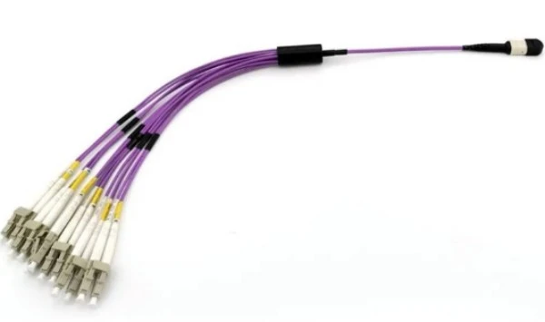
An MTP to LC cable connects high-density MTP connectors to individual LC duplex connectors, enabling you to break out parallel optics into separate channels. Your choice depends on fiber count (8, 12, or 24 fibers), fiber type (singlemode or multimode), polarity configuration, and network speed requirements.

Understanding MTP to LC Cable Configurations
MTP Breakout Cable (also known as MTP to LC breakout or fanout cables) serves as the bridge between multi-fiber MTP connectors and traditional LC duplex connections. These cables are essential when you need to connect QSFP-based switches to SFP-based infrastructure or distribute a single high-speed connection into multiple lower-speed channels.
The cable consists of one MTP connector on one end that fans out to multiple LC duplex pairs on the other end. This design allows one 40G or 100G connection to split into four 10G or 25G connections, or enables connection from parallel optic transceivers to patch panels and cassettes.
Fiber Count Determines Application
The number of fibers in your MTP to LC cable directly correlates with your network architecture and speed requirements.
8-Fiber Configurations
Eight-fiber cables connect one QSFP transceiver to four SFP transceivers. These cables work for Base-8 applications including 40GBASE-SR4, 100GBASE-SR4, and PSM4 transmission. The eight fibers provide four duplex channels, with each channel using one transmit and one receive fiber.
For 40G networks, an 8-fiber MTP to LC cable links a QSFP+ SR4 module to four SFP+ 10G modules. In 100G deployments, the same cable configuration connects a QSFP28 SR4 transceiver to four SFP28 25G transceivers. This makes 8-fiber cables the most common choice for modern data centers migrating from 10G to 40G or from 25G to 100G.
12-Fiber Configurations
Twelve-fiber cables provide six duplex channels and are the standard for traditional 10G and 25G duplex networking. These cables connect MTP-based patch panels to LC-based equipment, offering flexibility for future network upgrades.
A 12-fiber cable allows you to use eight fibers for active transmission while keeping four fibers as spares. This redundancy proves valuable during maintenance or when planning capacity expansion. Data centers often deploy 12-fiber infrastructure even when initially using only eight fibers, creating a path for seamless upgrades without rewiring.
24-Fiber Configurations
Twenty-four fiber cables merge 12 LC duplex pairs into a single MTP connection, providing the highest density option. These cables are used in high-density patch panel applications and for 10G to 100G migration scenarios.
A single 24-fiber cable can replace 12 individual duplex LC cables, dramatically reducing cable congestion in crowded racks. For data centers managing hundreds of connections, this density improvement translates to better airflow, easier cable management, and more efficient use of rack space.
Singlemode vs Multimode Selection
Your fiber type choice impacts transmission distance, cost, and compatibility with existing infrastructure.
Multimode Fiber Characteristics
Multimode MTP to LC cables use 50/125μm core diameter fibers, typically in OM3, OM4, or OM5 grades. These cables work with LED or VCSEL light sources and are optimal for distances under 550 meters.
OM4 multimode provides 4700 MHz·km bandwidth and supports 10G transmissions up to 550 meters and 40G/100G transmissions up to 150 meters. Most data centers standardize on OM4 because it handles both current and near-future speed requirements without limiting transmission distance within a single building.
Multimode cables are more cost-effective than singlemode options. The transceivers cost less, installation requires less precision, and the larger core diameter makes connector mating more forgiving. For intra-building connections where distances stay under 300 meters, multimode represents the practical choice.
Singlemode Fiber Characteristics
Singlemode cables use 9/125μm OS2 fiber with a much smaller core diameter. These cables work with laser light sources and support transmission distances from 2 kilometers to over 40 kilometers depending on the transceiver type.
For 40G networks, singlemode MTP to LC cables enable PSM4 (Parallel Single Mode 4) transmission over eight fibers, reaching distances up to 2 kilometers. The 100G PSM4 transceivers using singlemode breakout cables achieve similar distances, making them ideal for campus networks or connections between buildings.
Singlemode fiber costs more upfront but provides future-proofing through its distance capability and wavelength flexibility. Networks planning long-distance links or anticipating speed upgrades beyond 100G should invest in singlemode infrastructure.
Distance and Application Considerations
Choose multimode when all connections stay within 300 meters and cost sensitivity matters. Campus networks with multiple buildings separated by more than 500 meters require singlemode cables. Data centers spanning multiple floors often use multimode within each floor and singlemode for vertical connections between floors.
Temperature stability also differs between fiber types. Singlemode fiber maintains performance across wider temperature ranges, making it preferable for outdoor runs or areas with variable environmental control.
Polarity Configuration Guide
Polarity ensures transmit fibers connect to receive fibers at the opposite end. MTP to LC cables come in three polarity types: Type A, Type B, and Type C.
Type B Polarity (Most Common)
Type B cables reverse fiber positions from end to end, with position 1 mapping to position 12 and position 2 to position 11. Both MTP connectors have keys facing up, and only straight-through (A-to-B) duplex patch cords are needed.
This polarity is recommended for 40G and 100G parallel optics because it maintains consistent patching on both ends. When you connect a QSFP+ transceiver to four SFP+ transceivers using a Type B cable, the transmit lanes automatically align with receive lanes without requiring special crossover patch cords.
Type B cables work with key-up-to-key-up MTP adapters and are the industry standard for Base-8 applications. All QSFP type transceivers (QSFP+, QSFP28, QSFP-DD) with MPO-12f ports use male ferrules with guide pins, requiring female MTP connectors on the breakout cable.
Type A Polarity
Type A cables provide straight-through mapping where position 1 connects to position 1 and position 12 to position 12. One end has the key up while the opposite end has the key down.
This polarity requires using standard A-to-B patch cords on one side and crossover A-to-A patch cords on the other side to achieve proper transmit-to-receive alignment. Type A works well for duplex applications but adds complexity in 40G/100G deployments because you must track which end requires which patch cord type.
Type C Polarity
Type C cables implement pair-wise crossover where fibers 1 and 2 swap positions, fibers 3 and 4 swap, and so on. This polarity suits duplex breakout applications where the cable connects to individual LC pairs rather than parallel optics.
Type C is less common in modern deployments because it serves specific use cases. Most data centers standardize on Type B to simplify inventory and reduce installation errors.
Gender and Pin Considerations
MTP connectors come in male (with pins) and female (without pins) versions. QSFP transceivers have male ports, requiring female MTP connectors on cables. When connecting two MTP cables, you need one male and one female connector to ensure proper fiber alignment.
Guide pins in male connectors fit into alignment holes in female connectors, creating precise fiber-to-fiber contact. Attempting to mate two female or two male connectors results in damaged fibers or no connection.
Network Speed and Transceiver Compatibility
Your network speed determines which fiber count and configuration you need.
40G Networks
For 40GBASE-SR4 applications using multimode fiber, an 8-fiber Type B cable connects one QSFP+ SR4 transceiver to four SFP+ 10G transceivers. This allows a single 40G port to fan out to four separate 10G connections, useful when connecting a 40G switch to older 10G infrastructure.
For longer 40G links over singlemode fiber, 40GBASE-PLR4 transceivers also use 8-fiber breakout cables. These achieve distances up to 10 kilometers, enabling connections between data center buildings or floors.
100G Networks
100GBASE-SR4 transceivers on multimode fiber connect through 8-fiber cables, reaching 100 meters over OM4 fiber. One QSFP28 SR4 module fans out to four SFP28 25G modules, allowing 100G switch ports to connect to 25G server interfaces.
For extended reach, 100G PSM4 transceivers on singlemode fiber use 8-fiber breakout cables and achieve distances up to 2 kilometers. This configuration is common in campus networks or metro area networks requiring 100G bandwidth with moderate distance.
200G and 400G Networks
As networks scale to 200G and 400G, cable requirements evolve. 200G DR4 transceivers still use 8-fiber breakout cables, maintaining the four-lane architecture. However, 400G deployments often use 16-fiber configurations or multiple 8-fiber cables depending on the transceiver type (SR8, DR4+, or FR4).
For 400G DR4 applications, an 8-fiber cable connects one QSFP-DD transceiver to four 100G modules, each using PAM4 encoding to achieve 100G per lane.
Cable Length and Installation Factors
MTP to LC cables are available in standard lengths from 0.5 meters to 100 meters, with custom lengths available on request.
Rack-Level Connections
For connections within the same rack or adjacent racks, 1-3 meter cables provide adequate length without excess slack. These shorter cables reduce clutter and improve airflow around equipment. When connecting top-of-rack switches to servers within the same 42U rack, 1.5 meter cables typically suffice.
Row-Level Connections
Connections spanning multiple racks in the same row typically require 5-10 meter cables. This accounts for vertical routing up to cable trays, horizontal runs across trays, and drop-downs to equipment. Always measure the actual cable path rather than straight-line distance, adding 20-30% extra length for routing flexibility and service loops.
LC Tail Length and Stagger
The individual LC tails (the duplex connectors at the breakout end) typically measure 0.3 meters from the breakout module to the LC connector. This length works well for connecting to patch panels or nearby equipment.
Staggered tail configurations space the LC pairs at different lengths (typically 0.3m, 0.4m, 0.5m, 0.6m) to reduce congestion at the termination point. When connecting all four LC pairs to a small area, staggered tails make individual cables easier to identify and manage.
Jacket Rating Requirements
MTP to LC cables come with different jacket ratings based on installation location. Plenum-rated (OFNP) cables contain fire-retardant materials that produce less smoke during burning, required by building codes for air-handling spaces. Riser-rated (OFNR) cables meet requirements for vertical runs between floors. Low-Smoke Zero-Halogen (LSZH) cables comply with European fire safety standards.
In the United States, plenum spaces (areas above drop ceilings used for air circulation) require OFNP-rated cables. Verify local building codes before purchasing cables, as using inappropriate jacket types can fail inspections or void insurance.
MTP Connector Quality Considerations
Not all MTP connectors perform equally. The MTP brand, trademarked by US Conec, represents a higher-performing version of generic MPO connectors.
MTP vs Generic MPO
MTP connectors feature tighter manufacturing tolerances, stronger springs, and removable housings. These improvements reduce insertion loss and maintain performance over repeated mating cycles. Generic MPO connectors may work initially but often show degraded performance after 10-20 mating cycles due to spring weakening or ferrule wear.
The ferrule quality makes a substantial difference. MTP Elite and MTP Pro ferrules from US Conec provide insertion loss under 0.35dB and return loss better than 55dB. Generic MPO ferrules may show insertion loss above 0.75dB, which becomes problematic in multi-connection channels where losses accumulate.
Pin Configuration and Alignment
The alignment pins in male MTP connectors must be in excellent condition. Bent or damaged pins cause connection failures or high loss. Female MTP connectors contain precision alignment holes that guide the pins during mating.
Some manufacturers offer elliptical pin designs that provide self-centering during mating, reducing the chance of pin damage. However, these specialty pins must mate with compatible female connectors, potentially limiting interoperability with other vendors' equipment.
Connector End Face Polish
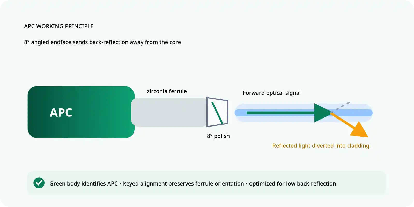
MTP connectors use either UPC (Ultra Physical Contact) or APC (Angled Physical Contact) polish. UPC polish creates a slightly curved end face that reduces air gaps when connectors mate. APC polish adds an 8-degree angle that deflects back-reflections away from the fiber core.
For multimode applications, UPC polish is standard and provides adequate performance. Singlemode applications benefit from APC polish when low return loss matters, particularly for systems sensitive to back-reflections like coherent optics or high-power transmitters.
The LC connectors on the breakout end typically use UPC polish even when the MTP end has APC. This mixed polish configuration (MTP-APC to LC-UPC) is common in singlemode breakout cables because LC transceivers typically have UPC interfaces.
Testing and Quality Verification
Before deploying MTP to LC cables, verify their performance through proper testing.
Insertion Loss Testing
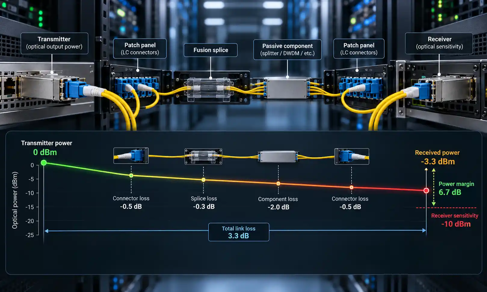
Insertion loss measures how much signal power the cable and connectors absorb. For multimode cables, acceptable insertion loss is under 0.75dB per connection. Singlemode cables should show under 0.5dB insertion loss.
Test each fiber pair individually using a light source and power meter. Document the results because high insertion loss on specific fibers indicates connection problems that will cause link failures when transceivers are installed.
Return Loss Testing
Return loss measures how much light reflects back toward the source. Higher return loss numbers indicate better performance. Multimode systems require return loss above 20dB, while singlemode systems need above 40dB for UPC and above 60dB for APC connections.
Poor return loss usually indicates dirty connectors or physical damage to fiber end faces. Clean all connectors before testing, and reject cables showing return loss below specifications.
Polarity Verification
Before installation, verify polarity by visually inspecting the fiber positions at each end. For Type B cables, position 1 at the MTP end should map to position 12 at the opposite MTP end (when connected through the LC pairs).
Some installers use visual fault locators (VFLs) to verify fiber mapping. Insert the VFL at one end and confirm which LC pair lights up, systematically checking all pairs match the expected polarity pattern.
Common Installation Mistakes to Avoid
Many deployment problems stem from avoidable installation errors.
Wrong Polarity Type
Using Type A cables when your infrastructure expects Type B causes transmit-receive mismatches. Before ordering cables, verify what polarity your patch panels, cassettes, and transceivers require. Some cassettes are universal and work with any polarity, while others are polarity-specific.
Gender Mismatch
Ordering male MTP connectors when your transceivers have male ports creates connection impossibility. QSFP transceivers always have male MPO ports, requiring female MTP cables. When extending MTP connections, you need one male and one female cable.
Insufficient Cable Management
MTP to LC cables create multiple individual fibers at the breakout point. Without proper cable management, these individual fibers create tangles. Use cable combs, velcro straps, or spiral wrap to keep the LC tails organized.
Ignoring Minimum Bend Radius
MTP fiber cables have minimum bend radius specifications, typically 10 times the cable diameter. Tight bends damage the internal fibers, increasing attenuation or breaking fibers entirely. When routing cables through tight spaces, choose bend-insensitive fiber specifications or use larger radius pathways.
Skipping Connector Cleaning
Dirty MTP or LC connectors cause immediate signal loss. Always clean connectors before mating using appropriate cleaning tools. For MTP connectors, use specialized MPO cleaning cassettes that clean all 12 fiber end faces simultaneously.
Future-Proofing Your Cable Infrastructure
When selecting MTP to LC cables, consider how your network will evolve over the next 3-5 years.
Overprovisioning Fiber Count
Installing 12-fiber cables when you currently need only 8 fibers provides upgrade capacity. The cost difference between 8-fiber and 12-fiber cables is minimal compared to the expense of rewiring later. Those extra four fibers enable network speed upgrades or additional connections without physical infrastructure changes.
Higher-Grade Fiber Selection
Choosing OM4 instead of OM3 multimode fiber costs slightly more but supports longer distances and higher speeds. OM4 handles 40G/100G transmission up to 150 meters, while OM3 limits these speeds to 100 meters. For many data centers, this distance difference determines whether you can span multiple rows with a single connection.
For singlemode installations, OS2 fiber supports all current and foreseeable singlemode applications. Unlike multimode which has multiple grades, singlemode fiber standards remain stable, making OS2 a reliable long-term choice.
Modular Design Approach
Rather than running individual breakout cables from switches to servers, consider using MTP to LC cables in conjunction with MTP cassettes at patch panels. This modular approach allows you to change connection patterns by swapping cassettes rather than replacing cables, providing flexibility as network architecture evolves.
Frequently Asked Questions
What does the "female" or "male" designation mean for MTP connectors?
Male MTP connectors have two metal guide pins protruding from the ferrule face, while female connectors have alignment holes instead of pins. QSFP transceivers use male MPO interfaces, so you need female MTP connectors on your breakout cables. When connecting two MTP cables together, one must be male and one female for proper fiber alignment.
Can I use multimode transceivers with singlemode MTP to LC cables?
No, you must match the fiber type to your transceivers. Multimode transceivers (SR4 types) require multimode cables, while singlemode transceivers (PSM4, PLR4, LR4 types) need singlemode cables. Using the wrong fiber type results in no connection or extremely high signal loss. The core diameter difference between singlemode (9μm) and multimode (50μm) makes them incompatible.
How do I know which polarity type my network uses?
Check your MTP cassettes or patch panels for polarity markings. Most modern data center equipment uses Type B polarity. If you're connecting directly from a QSFP+ transceiver to SFP+ transceivers without intermediate cassettes, Type B cables provide the correct transmit-receive mapping. Documentation from your switch vendor typically specifies required polarity for direct connections.
What's the maximum length for an MTP to LC cable?
Standard catalog lengths go up to 100 meters, with custom lengths available to 150 meters. However, practical maximum length depends on your total channel loss budget. Each connector adds insertion loss, and the fiber itself has attenuation per meter. For 40G/100G links using multimode fiber, keep total channel length under the transceiver's rated distance (typically 100-150 meters for SR4). Singlemode cables can span several kilometers when using appropriate transceivers.
Your MTP to LC cable selection hinges on understanding your network's specific requirements: the number of fibers needed, whether singlemode or multimode fiber fits your distance requirements, the correct polarity for your equipment, and appropriate cable length. Start by identifying your transceiver types (QSFP+ for 40G or QSFP28 for 100G), verify their MPO connector gender (typically male), determine if you're connecting to other transceivers or to patch panels, and measure your required cable routing distance. With these factors determined, selecting the right cable becomes straightforward rather than overwhelming.