multimode optical fiber
Multimode fiber (multimode fiber or MM fiber or optical fiber) is a type of optical fiber used primarily for short-distance communications, such as within buildings or on campus. Typical multimode links have data rates of 10 Mbit/s to 10 Gbit/s over link lengths of up to 600 meters, which is more than sufficient for most premises applications.
Application areas
The equipment used for multi-mode fiber optic communication is cheaper than the equipment used for single-mode fiber optic communication. Typical transmission speed and distance limits are 100 Mbit/s up to 2 km (100BASE-FX), 1 Gbit/s up to 220-550 m (1000BASE-SX), and 10 Gbit/s up to 300 m (10GBASE-SR )), such as SR 10G SFP+ optical module, 10G XFP optical module, 10G X2 optical module and other 10G modules.
Multimode fiber is commonly used in building backbone applications due to its high capacity and reliability. More and more users are taking advantage of fiber optics closer to the user by connecting it to their desktop or area. Standards-compliant architectures such as centralized cabling and fiber-to-telco cabinets allow users to take advantage of fiber's distance capabilities by centralizing electronics in the telecom room, rather than having active electronics on every floor.
Comparison with single-mode fiber
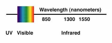
The main difference between multimode fiber and single-mode fiber is that the core diameter of the former is much larger, typically 50-100 microns; much larger than the wavelength of the light carried within it. Multimode fiber has a higher "light gathering" ability than single-mode fiber. In practice, the larger core size simplifies connectivity and also allows the use of lower-cost electronics such as light-emitting diodes (LEDs) and vertical-cavity surface-emitting lasers (VCSELs) operating at 850 nm and 1300 nm wavelengths (in telecommunications The single-mode fiber used operates at 1310 or 1550 nm and requires a more expensive laser source (single-mode fiber is suitable for almost all visible light wavelengths). However, multimode fiber has lower bandwidth-distance product limitations than single-mode fiber. Because multimode fiber has a larger core size than single-mode fiber, it supports multiple modes of propagation; therefore it is limited by modal dispersion, whereas single-mode fiber is not. LED light sources, sometimes used with multimode fiber, produce a range of wavelengths, each traveling at a different speed. In contrast, lasers used to drive single-mode fiber produce coherent light at a single wavelength. This dispersion is another limitation on the useful length of multimode fiber optic cables. Due to their larger core size, multimode fibers have a higher numerical aperture, which means they can collect more light than single-mode fibers. Due to the modal dispersion in the fiber, multimode fiber has a higher pulse expansion rate than single-mode fiber, which limits the information transmission capacity of multimode fiber. Single-mode fiber is most commonly used for high-precision scientific research because allowing only one mode of propagation of light makes it easier for the light to focus correctly. Jacket color is sometimes used to distinguish multimode fiber optic patch cords/cables from singlemode, but it cannot always be relied upon to distinguish cable types. For civilian applications, standard TIA-598C recommends yellow jacketing for single-mode fiber and orange jacketing for 50/125 µm (OM2) and 62.5/125 µm (OM1) multimode fiber. Aqua is recommended for use with 50/125 µm "laser optimized" OM3 fiber.
type
Multimode fiber is described by its core and cladding diameters. Therefore, a 62.5/125 µm multimode fiber has a core size of 62.5 micrometers (µm) and a cladding diameter of 125 µm. The transition between core and cladding can be sharp, which is called a step index profile, or it can be a gradual transition, which is called a graded index profile. The two types have different dispersion characteristics and therefore different effective propagation distances. Furthermore, multimode fiber is described using the classification system (OM1, OM2, and OM3) established by the ISO 11801 standard, which is based on modal bandwidth multimode fiber. OM4 (defined in TIA-492-AAAD) was finalized in August 2009 and published by TIA in late 2009. OM4 cables will support 125m links at 40 and 100 Gbit/s.
For many years, 62.5/125 µm (OM1) and conventional 50/125 µm multimode fiber (OM2) have been widely deployed in premises applications. These fibers can easily support applications ranging from Ethernet (10 Mbit/s) to Gigabit Ethernet (1 Gbit/s) and are ideal for use with LED emitters due to their relatively large core size. Newer deployments typically use laser-optimized 50/125 µm multimode fiber (OM3). Fiber optics that meet this designation provide sufficient bandwidth to support 10 Gigabit Ethernet up to 300 meters. Since the release of the standard, fiber optic manufacturers have greatly improved their manufacturing processes and can create cables that support 10 GbE up to 550 meters. Laser Optimized Multimode Fiber (LOMMF) is designed for use with 850 nm VCSELs and is widely used in MM SFP transceivers including SPT-P851G-S5D, SPT-P854G-S3xD, and others.
The migration to LOMMF/OM3 has already occurred as users upgrade to higher-speed networks. LEDs have a maximum modulation rate of 622 Mbit/s because they cannot turn on/off fast enough to support higher bandwidth applications. VCSELs are capable of modulation in excess of 10 Gbit/s and are used in many high-speed networks.
Variations in VCSEL power distribution as well as fiber uniformity can cause modal dispersion, which can be measured by differential modal delay (DMD). Modal dispersion is an effect caused by the different speeds of individual modes in a light pulse. The net effect is to cause the light pulses to separate or travel a distance that makes it difficult for the receiver to identify the individual 1s and 0s (this is called intersymbol interference). The larger the length, the larger the modal dispersion. To combat modal dispersion, LOMMF is manufactured in a way that eliminates changes in the fiber that could affect the speed at which light pulses travel. The refractive index profile is enhanced to enable VCSEL transmission and prevent pulse spreading. As a result, fiber can maintain signal integrity over longer distances, maximizing bandwidth.
|
Transmission Standards |
100 Mb Ethernet |
1 Gb (1000 Mb) Ethernet |
10 Gb Ethernet |
40 Gb Ethernet |
100 Gb Ethernet |
|
OM1 (62.5/125) |
up to 550 meters(SX) |
220 meters(SR) |
33 meters(SR) |
NOT SUPPORTED |
NOT SUPPORTED |
|
OM2 (50/125) |
up to 550 meters(SX) |
550 meters(SR) |
82 meters(SR) |
NOT SUPPORTED |
NOT SUPPORTED |
|
OM3 (50/125) |
up to 550 meters(SX) |
550 meters(SR) |
300 meters(SR) |
100 meters |
100 meters |
|
OM4 (50/125) |
up to 550 meters(SX) |
550 meters(SR) |
>400 meters(SR) |
125 meters |
125 meters |
Multimode fiber optic connector types
The types of multi-mode optical fiber connectors circulating on the market include ST, SC, FC, LC, MU, E2000, MTRJ, SMA, DIN and MTP&MPO. The most commonly used types of optical fiber connectors are ST, SC, FC and LC. Each has its own strengths, weaknesses, and abilities. So what are the differences and what do they mean for implementation? This table of common multimode fiber optic connectors outlines the pros and cons.
| Connector | ferrule size | Insertion loss (dB) | Application features |
| SC | φ2.5mm ceramic | 0.25-0.5 | Mainstream, reliable, rapid deployment, applicable |
| LC | φ1.25mm ceramic | 0.25-0.5 | High density, high cost performance, on-site adaptability |
| FC | φ2.5mm ceramic | 0.25-0.5 | High precision, vibration environment, on-site adaptation |
| ST | φ2.5mm ceramic | 0.25-0.5 | Reliable and stable, field adaptable |