In data centers, high-density fiber cabling is the core technology for increasing capacity, optimizing bandwidth efficiency and space utilization. The following is a detailed analysis of the key methods to enhance data center capacity from the dimensions of hardware selection, topology design, and management strategy:
I. Hard ware level: selection and deployment of high-density fiber optic components


1. Use high-density fiber optic connectors and patch panels
MPO/MTP connectors: support 12-core/24-core high-density integration, and the single-port density is increased by more than 50% compared to traditional LC/SC connectors, which is suitable for high-speed interconnection between trunk optical cables and switches (such as 400G/800G networks).
High-density patch panels (HDD): reduce cabinet space occupancy through compact design (such as 1U rack accommodating more than 48 cores). For example, using a 19-inch rack-mounted high-density fiber optic patch panel, a single cabinet can deploy more than 1,000 cores of optical fiber.
Micro Cable: With a diameter of only 0.5-2mm, it is light in weight and has a small bending radius (≤10mm). It can be densely wired in a small space, reducing the occupancy rate of the pipeline.
2. Upgrade fiber types and transmission technologies
The synergy between multimode fiber (MMF) and single-mode fiber (SMF):
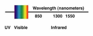
OM4/OM5 multimode fiber is used for short distances (<300 meters), supporting 40G/100G high-speed transmission;
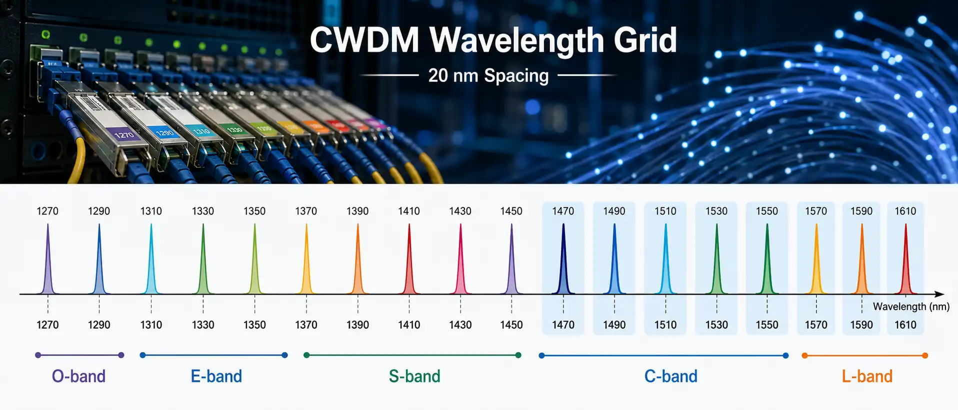
OS2 single-mode fiber is used for long distances or core networks, and with DWDM (dense wavelength division multiplexing) technology, the single-core transmission capacity is increased to Tbps level.
Space division multiplexing (SDM) and few-mode fiber (FMF): Through multi-core fiber or mode splitting technology, multiple signals are transmitted in the same optical cable, breaking through the traditional single-core capacity limitation.
2. Cabling topology and architecture optimization
1. Modular and pre-terminated cabling design
Pre-terminated optical cable components: Complete fiber termination and testing in the factory (such as MPO-LC/MPO-MPO jumpers), and only plug and unplug connections are required on site, reducing construction time and loss (traditional fusion loss is about 0.1dB/point, pre-terminated loss < 0.05dB).
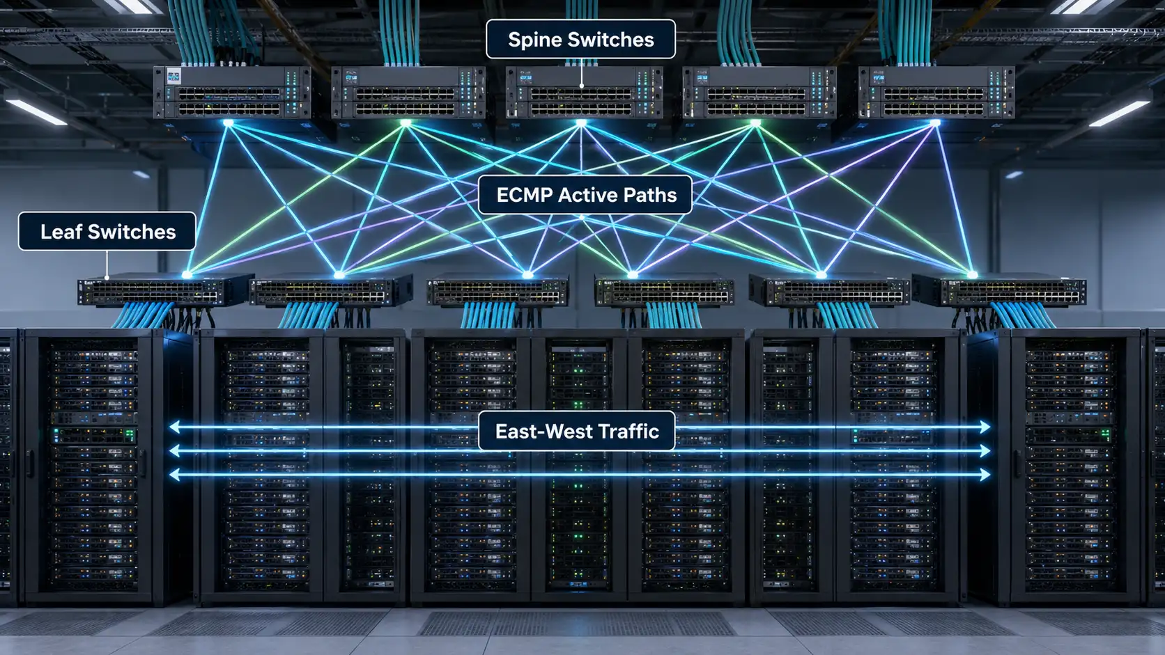
Leaf-Spine architecture: With the Spine switch as the core, the Leaf switch is distributed to connect servers, and non-blocking interconnection is achieved through high-density optical fiber, supporting high-density deployment of 10G/100M ports.
2. Hierarchical optimization of horizontal and backbone cabling
Horizontal cabling (server to access layer): A hybrid solution of Category 6/8 copper cable and multimode optical fiber is used. Copper cable is used for low-speed connections below 10G, and optical fiber is used for 40G/100G high-speed server clusters.
Backbone cabling (core layer interconnection): Use single-mode fiber + DWDM technology, such as 640G transmission through 16-wave DWDM in 4-core optical cables, replacing traditional multi-core optical cables.
III. Space and heat management
1. Physical layout optimization of high-density cabling
Structural design of wiring troughs and bridges:
Use upper wiring (ceiling bridge) or lower wiring (floor mezzanine) to separate power cables and optical fibers to avoid electromagnetic interference;
Use cable organizers and binding tapes to standardize wiring, ensure that the bending radius is ≥20 times the fiber diameter (such as 2mm optical cables require ≥40mm bending radius), and reduce signal loss.
Isolation of hot and cold channels and enhanced heat dissipation:
High-density cabinets (such as 42U cabinets deploying 80 servers) need to be equipped with inter-row air conditioners to ensure that the temperature of the fiber connector is ≤25℃ (exceeding 35℃ will cause increased loss).
2. Loss control for high-density cabling
Insertion loss (IL) and return loss (RL) test: Use an optical time domain reflectometer (OTDR) to detect the loss of each section of optical fiber, requiring IL < 0.5dB, RL > 50dB, to avoid signal reflection causing bit errors.
IV. Intelligent management and automation system
1. Intelligent fiber management system (iFMS)
Real-time monitoring of fiber connection status through RFID tags or electronic distribution frames (EDF), automatic generation of topology maps, support fault location (such as loose ports, fiber breakage), and reduce manual inspection time (efficiency increased by more than 70%).
Integrated network management system (NMS) to achieve linkage monitoring of bandwidth usage and fiber links, such as automatically triggering expansion reminders when the utilization rate of a link exceeds 80%.
2. Automated deployment and operation and maintenance tools
Use robot-assisted cabling (such as robotic arms to install MPO connectors) to improve construction accuracy in high-density environments;
Introduce AI algorithms to predict fiber life and failure risks, such as replacing aging fibers in advance through historical loss data modeling.
V. Standardization and future scalability
1. Comply with industry standards and compatible design
Comply with TIA-942 data center cabling standards, such as reserving 30% redundant cores for trunk optical cables and 20% ports for horizontal cabling;
Adopt open interfaces (such as intelligent patch panels that support SNMP protocol) and be compatible with equipment from different manufacturers (such as Cisco and Juniper switches).
2. Future-oriented capacity reservation
Fiber capacity redundancy: reserve 20%-30% spare cores in trunk optical cables to support future 100G/400G upgrades;
Space reservation: reserve 10%-15% of empty slots in the cabinet for adding high-density patch panels or switches.
VI. Typical cases and technology trends
Large cloud data center practice: A cloud computing vendor uses MPO pre-terminated optical cables + 1U high-density patch panels to increase the fiber capacity of a single cabinet from 144 cores to 576 cores, while increasing the wiring efficiency by 4 times.
Technology trends:
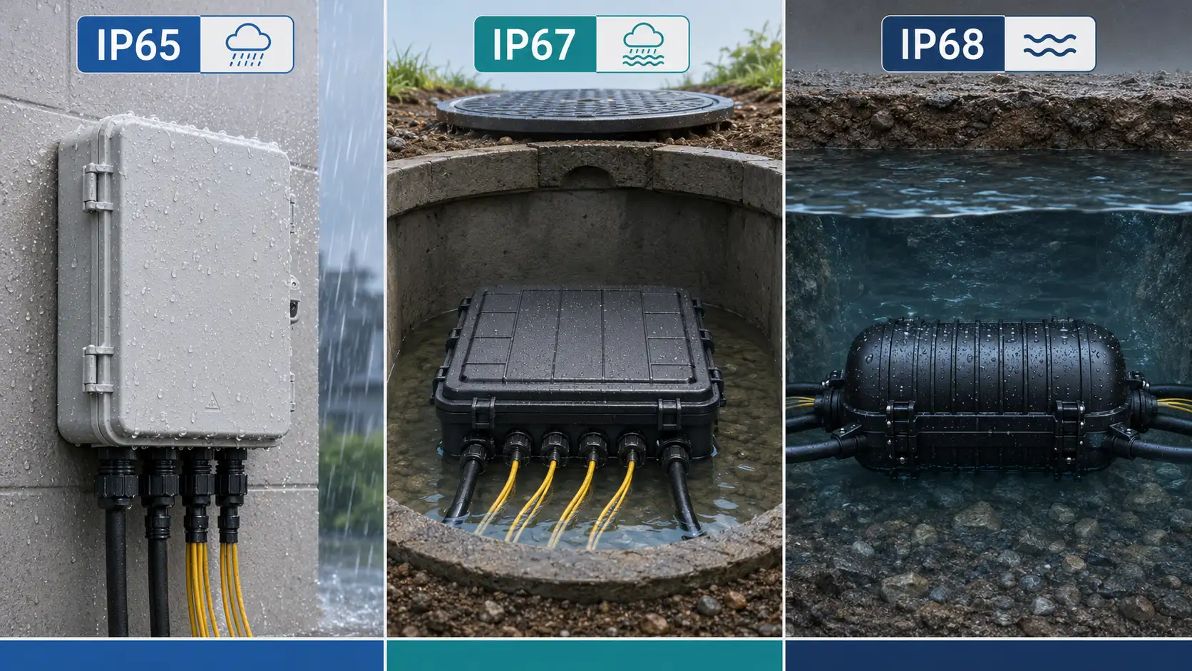
Cabinet in liquid cooling environment: For immersion liquid cooling data centers, waterproof fiber connectors (such as IP68 grade) are used to prevent coolant from seeping into the connectors;
Optoelectronic fusion chip: Integrate the fiber transceiver into the switch chip to reduce the number of jumpers in the cabinet and further improve the density (such as Cisco 800G switch uses optoelectronic integrated modules).
High-density fiber cabling maximizes bandwidth capacity in a limited space through the combination strategy of "hardware upgrade + architecture optimization + intelligent management". The key is to balance density, loss, heat dissipation and maintainability, while supporting future expansion with standardized design. When implementing, it is necessary to select an appropriate technical solution based on the scale of the data center (such as ultra-large-scale cloud data center vs. enterprise-level data center). For example, DWDM+MPO is preferred for large scenarios, and pre-termination + intelligent management system is emphasized for small and medium scenarios.