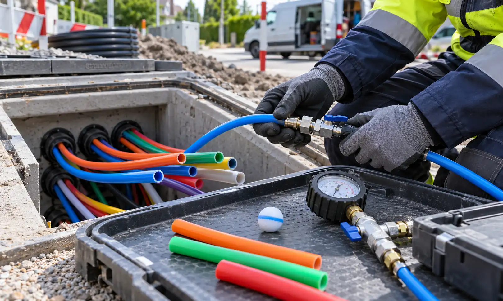
A passed microduct proofing test does not guarantee that an installed route is ready for every cable-blowing job. A field check shows whether the inspected section meets its stated inspection conditions. IEC 60794-1-131:2026 Method E31 addresses inner clearance in a microduct specimen or assembly, while IEC 60794-1-124:2025 Method E24 evaluates how microduct cabling behaves on specified blowing-test tracks. These results answer different questions. Before releasing a route for installation, engineers need to match the evidence to the installed duct, the intended cable and the equipment and conditions of the planned blow.
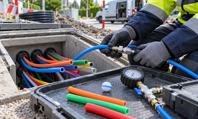
Does a Passed Microduct Proofing Test Guarantee Blowing Success?
No. A test ball or mandrel that reaches the receiving end establishes that the selected test object traversed the inspected section under the recorded conditions. It does not measure the resistance that develops when a much longer cable occupies several bends at once. Nor does the result establish whether the compressor, blower and route can sustain the airflow and mechanical loading required by the actual cable.
The distinction matters on networks built for staged cable deployment. In an air-blown micro-fiber system, empty microducts may remain in place until a later cable installation. A factory microduct result cannot account for damage, contaminated joints or route changes introduced after the duct was supplied. Equally, a field pass recorded months earlier should be checked against any later civil works or repairs before it is used to authorize a new installation.
Approval therefore needs an explicit scope. A team may accept the proofing record as evidence that a particular section passed a specified clearance check, while still requiring pressure-integrity records, route information and a cable-to-duct assessment before blowing begins.
What Does IEC 60794-1-131:2026 Method E31 Test?
IEC 60794-1-131:2026, Method E31 specifies the microduct inner clearance test for ducts used to install optical fibre cables by blowing. The 2026 publication establishes E31 as a separate standard, replacing the method previously included in IEC 60794-1-21 and its amendment.
Its result concerns the tested specimen or microduct assembly and the prescribed test conditions. Depending on the qualification plan, inner clearance evidence may be considered following manufacturing or other relevant mechanical or environmental testing. The record should identify the specimen, test procedure, applicable clearance requirement and result. Without those details, a simple statement that the duct is "E31 tested" does not establish which configuration or acceptance condition was evaluated.
E31 is not a blanket certification of a buried or installed route. The tested sample does not represent every coupling, bend, repair or locally compressed section between two access points. It also does not establish the blowing distance achievable with a specified cable. In particular, do not transfer test-object dimensions or acceptance conditions from a manufacturer's field proofing procedure into E31 without checking the applicable standard and product specification.

How Is Field Microduct Proofing Different From IEC E31?
Field proofing examines the installed route or defined route section rather than a controlled production sample. The inspection may include air passage, cleaning, passage of a specified ball or mandrel, and a separate pressure-integrity check. The exact combination is set by the project specification and the microduct system manufacturer's procedure; passing one check does not imply the others were performed.
Cleaning can reveal debris or water that entered during construction. A passage test can identify restrictions that stop the selected test object. A pressure-integrity test can provide evidence about leaks in the tested duct and couplings under its stated conditions. None of these observations is a direct measurement of microcable friction or predicted installation distance. The Fiber Optic Association's outside-plant installation guidance treats cleaning, passage checks and pressure tests as distinct parts of duct integrity testing.
Joint details deserve separate attention. A correctly sized duct can still have a restricted or misaligned transition where sections meet. For a route using microduct straight connectors, the installer should verify the selected fitting's actual port sizes, connection arrangement and suitability for the duct system, rather than assume the nominal duct ID remains unobstructed through every joint. Product pressure ratings and fitting designations should be confirmed against the current datasheet before being applied to a project.
| Test or check | Test object | What the result supports | What it does not establish | Evidence to retain |
|---|---|---|---|---|
| IEC E31 inner clearance | Defined microduct specimen or assembly | Compliance of that specimen with the specified inner-clearance procedure and requirement | Condition of every section of an installed route | Sample identity, edition, specified requirement, method and outcome |
| Field passage or proofing check | Identified installed section | Passage of the selected test object through the checked section under the recorded conditions | Suitability for every cable OD, stiffness or blowing distance | Section ID, object shape and dimensions, method, observations and outcome |
| Field pressure-integrity check | Installed section, including relevant fittings | Pressure behaviour of that section under the specified test procedure | Freedom from every mechanical restriction or sufficient air delivery during actual blowing | Test pressure, duration, conditions, recorded change and acceptance limit |
| IEC E24 blowing test | Specified cable and test microduct system | Observed blowing behaviour on the defined test track and conditions | Equivalent performance on every installed route | Cable and duct identification, track method, settings, measured performance and conditions |
Why Does Proofing Ball Diameter Change the Result?
A microduct test ball is a physical gauge, not a substitute for an installed cable. The dimensions and shape of the object determine which restrictions it can reveal. Passing a smaller sphere does not prove that a larger sphere, a longer mandrel or a particular microcable can traverse the same route. The recorded test method matters as much as the word "pass".
Consider a hypothetical microduct with an 8 mm nominal inner diameter. A 6.4 mm proofing ball has a diameter equal to 80% of nominal ID; a 6.8 mm ball is 85%. The latter is 0.4 mm larger. If the 6.4 mm ball passes but the 6.8 mm ball does not, the two checks have produced different evidence about the route. Neither result alone establishes the local restriction's exact geometry or proves whether a particular cable will blow successfully.
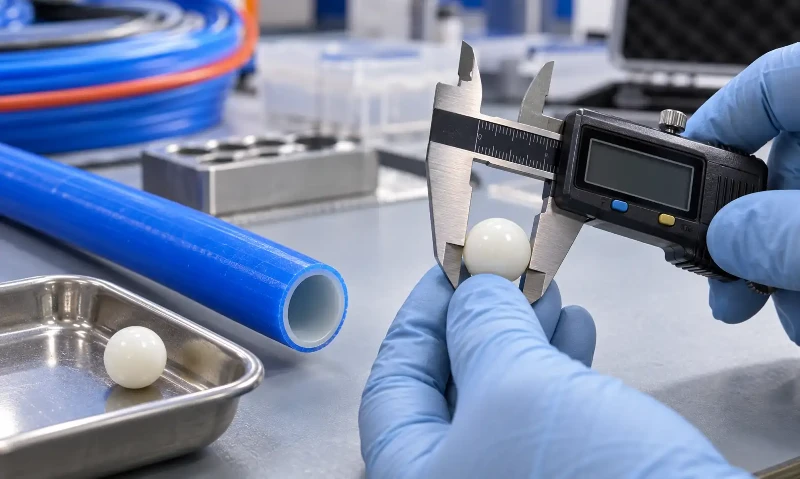
| Ball diameter | Ball diameter / nominal duct ID | Interpretation |
|---|---|---|
| 6.4 mm | 80% | Passage of a 6.4 mm sphere under the selected field method |
| 6.8 mm | 85% | A different, more restrictive passage check for a spherical object |
These percentages describe test-object diameter relative to nominal duct ID; they are not cable cross-sectional fill percentages or universal IEC E31 acceptance limits. A manufacturer's 80% or 85% field-check recommendation should be used only where applicable to the chosen duct system and project. For cable compatibility, compare actual cable OD, tolerances and construction with the duct's verified dimensions and the supplier's installation limits. A spherical test object does not replicate cable length or bending resistance.
Why Can a Proofed Microduct Still Fail During Blowing?
The microduct proofing test may have answered the passage question correctly, yet the installation can still stall. The causes should be investigated rather than inferred from a passing or failing ball test alone:
- Cable OD and construction. The supplied cable's actual diameter, dimensional tolerances, stiffness and jacket surface affect how it behaves inside a narrow duct.
- Route geometry. Multiple bends, elevation changes and actual routing deviations can create cumulative resistance that a short test object does not reproduce.
- Joint transitions. A coupling may allow a short ball through while a cable tip or a longer cable section behaves differently at that transition.
- Air delivery and installation settings. Blower feed force, available airflow, equipment configuration and operating limits influence the outcome even when field pressure checks have passed.
- Condition at the time of blowing. Water, debris, temperature and work performed after the last inspection can change the installation conditions.
This is why a cable's published diameter and nominal duct fit are only part of the review. A specific air-blown micro fiber optical cable configuration should be checked against its current product dimensions and the intended microduct route. A supplier's general statement of suitability for one microduct size should not be applied to every cable build or site condition without confirmation.
What Does IEC E24 Actually Evaluate?
IEC 60794-1-124:2025, Method E24 evaluates the blowing behaviour of microduct cabling in a defined test microduct or protected microduct system. Unlike E31, it is concerned with cable movement during an installation-type test. Its reported performance depends on the identified cable, microduct, test track and operating conditions.

Method A: Two Mandrels With the Same Curvature Direction
Method A uses two mandrels and two long straight sections between them, with bending in the same curvature direction. This controlled layout characterizes blowing behaviour for the prescribed arrangement. It should not be described as a test of an unrestricted straight route.
Method B: Three Mandrels With a Curvature Reversal
Method B uses three mandrels. The middle mandrel introduces both left- and right-hand bending into the route. The 2025 edition added this arrangement to represent a change in curvature direction that can arise on actual installations. It does not mean the method recreates a specific city network, or that its results convert directly into a field installation distance.
The 2025 standard also describes optional work relating to blowing an installed cable out and a crash test. Those procedures are separate from treating a sample clearance result as a cable-blowing approval. When evaluating E24 evidence, ask which track arrangement was used, what cable and microduct were tested, what conditions were recorded and how those conditions compare with the proposed installation.
Illustrative Case: A Proofed Route Where the Cable Stalls
Consider a hypothetical project using a 12/10 mm microduct and a microcable with a stated 8.1 mm outside diameter. A field team passes an 8 mm spherical proofing ball along the designated route and records a satisfactory pressure-integrity result under its chosen procedure. During cable blowing, the installation stalls near 400 m.
The ball's diameter was 80% of the duct's nominal 10 mm ID, but only 0.1 mm smaller than the cable's stated OD. The successful ball test demonstrates passage of that sphere under the recorded conditions. It does not establish that the cable has adequate clearance after tolerances, nor does it quantify the effects of bends, cable stiffness and airflow. The stall location alone does not prove that a bend, joint or obstruction caused the problem.
| Evidence | What it supports | What remains open |
|---|---|---|
| 8 mm sphere traversed the route | Specified passage check completed | Actual cable behaviour at bends and transitions |
| Pressure check met its stated project limit | Section met the selected pressure-integrity requirement | Whether the blower maintained suitable air delivery in operation |
| Cable stalled near 400 m | Installation performance was insufficient under the conditions used | Whether cause lies in cable, route, joint, settings or a combination |
| As-built route information available | Provides locations for targeted inspection | Whether actual geometry and joints match the records |
The next step is a targeted review of as-built geometry, actual cable OD, joint locations, recorded equipment settings and the condition of the affected route section. Further local inspection or a controlled installation trial may be appropriate if the contract and field conditions allow. This case is an engineering illustration, not a FOCC project report or a predicted failure threshold for 12/10 mm ducts.
What Evidence Supports Approval for the Next Step?
Field approval is not a contest between the largest proofing ball and the highest pressure reading. The report needs to show which question was tested and whether the results meet the requirement written for that test. A clearance sample report, route proofing log and blowing performance report should not be filed as interchangeable evidence.
| Review item | Evidence required | Reviewer's question | If missing or unsatisfactory |
|---|---|---|---|
| Duct identification | Manufacturer, product designation, batch and installed section IDs | Does the evidence apply to the product and route under review? | Request traceable identification |
| Dimensions | Nominal OD/ID, relevant tolerances and any measured dimensions | Are dimensions consistent with the approved design? | Obtain measurements or current specifications |
| Test method | IEC edition or named project/manufacturer field procedure | Is this sample testing, route proofing, pressure testing or a blowing test? | Clarify scope before acceptance |
| Passage object | Ball or mandrel shape, diameter, length where applicable, and route coverage | What restriction could this check have detected? | Request complete proofing record |
| Pressure integrity | Test conditions, applied pressure, duration, recorded results and project limit | Was the specified integrity procedure passed? | Complete or repeat the specified check if required |
| Route condition | Section length, as-built bends, joints, changes and date of inspection | Has anything changed since the test? | Inspect or update the relevant section |
| Cable compatibility | Actual cable OD and tolerance, construction, mechanical limits and applicable blowing data | Does the evidence concern the cable intended for this route? | Request product-specific assessment |
| Test outcome | Observed results, deviations, corrective work and retest status | Was the requirement met, or is the evidence incomplete? | Hold approval, request evidence or require corrective work as appropriate |
| Engineering disposition | Named reviewer, decision, remaining restrictions and date | Exactly which next step is authorized? | Do not treat an undocumented approval as a test result |
Accept for the defined next step means the available evidence is sufficient for the stated action under the applicable project requirements; it is not a guarantee of installation success. Request additional evidence applies when records are incomplete or do not cover the proposed work. Do not approve pending corrective action is appropriate where an applicable requirement was not met or an unresolved defect affects the intended operation. Missing documentation and an actual failed test are different findings and should be recorded separately.
Confirming Microcable and Microduct Compatibility
Once the inspection results have been interpreted, the remaining procurement decision is whether the proposed cable and microduct assembly match the route and installation plan. The review should cover the microduct's nominal and measured dimensions, the cable's actual OD and construction, fitting dimensions, installed section lengths, bend information and the proofing records available. ITU-T L.108 (08/2026) addresses optical fibre cable elements for microduct blowing-installation applications; it should not be used as a replacement for a project-specific field route acceptance procedure.
For a FOCC Fiber microcable inquiry, provide the duct OD/ID, selected fittings, fibre count, required cable construction, cable OD limits, relevant route layout, field test records and the required standard editions. These details allow the proposed configuration and available technical documentation to be reviewed against the stated project conditions. If the original records relate to a different duct size, cable build or installation route, additional verification may be needed.
Send the configuration and available reports to FOCC Fiber's technical sales team to discuss appropriate microcable options, fitting compatibility, supporting specifications and quotation requirements. The review should identify what is documented for the selected product, rather than assuming that a catalogue description establishes site-wide installation performance.
Frequently Asked Questions
Can an IEC E31 result replace proofing an installed microduct route?
No. E31 provides inner-clearance evidence for the tested specimen or assembly under the applicable method. Installed sections may have construction-related restrictions, contaminated joints or changes not present in the sample. Whether a new field check is required depends on the project acceptance procedure and the status of previous route records.
Does passing a proofing ball prove that a similarly sized cable will fit?
Not by itself. A sphere and a microcable differ in length, flexibility and interaction with bends and joints. Compare the test object's dimensions and shape with the cable's actual outside diameter, tolerances, construction and the specified duct-to-cable compatibility requirements.
Can IEC E24 laboratory blowing results be used to guarantee field blowing distance?
No. An E24 result characterizes the tested cable and microduct arrangement under documented conditions. It can inform an engineering review, but actual route geometry, duct condition and equipment settings can differ. Use the report alongside the installed-route evidence and the manufacturer's limits, not as a conversion formula for guaranteed field distance.